Table of Contents
Advertisement
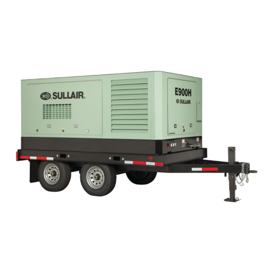
USER MANUAL
PORTABLE AIR COMPRESSOR
E900H
PART NUMBER:
02250203-986 R01
KEEP FOR
FUTURE
WARRANTY NOTICE
REFERENCE
SULLAIR CORPORATION
©
Failure to follow the instructions
The information in this manual is current
and procedures in this manual or,
as of its publication date, and applies to
misuse of this equipment will
compressor serial number:
VOID its warranty!
ELQ: 37212070248
ETQ: 201210010000
and all subsequent serial numbers.
Advertisement
Table of Contents

Related Manuals for Sullair E900H


Summary of Contents for Sullair E900H
- Page 1 USER MANUAL PORTABLE AIR COMPRESSOR E900H PART NUMBER: 02250203-986 R01 KEEP FOR FUTURE WARRANTY NOTICE REFERENCE SULLAIR CORPORATION © Failure to follow the instructions The information in this manual is current and procedures in this manual or, as of its publication date, and applies to...
- Page 2 AIR CARE SEMINAR TRAINING Sullair Air Care Seminars are courses that provide hands-on instruction for the proper operation, maintenance, and servicing of Sullair products. Individual seminars on portable compressors and compressor electrical systems are offered at regular intervals throughout the year at Sullair’s corporate headquarters training facility located at Michigan City, Indiana.
-
Page 3: Table Of Contents
ENTRAPMENT 1.11 IMPLEMENTATION OF LOCKOUT/TAGOUT SECTION 2—DESCRIPTION INTRODUCTION DESCRIPTION OF COMPONENTS SULLAIR COMPRESSOR UNIT, FUNCTIONAL DESCRIPTION AIR INLET SYSTEM, FUNCTIONAL DESCRIPTION COMPRESSOR DISCHARGE SYSTEM, FUNCTIONAL DESCRIPTION COMPRESSOR COOLING AND LUBRICATION SYSTEM, FUNCTION- AL DESCRIPTION CONTROL SYSTEM, FUNCTIONAL DESCRIPTION AFTERCOOLED AIR SYSTEM, FUNCTIONAL DESCRIPTION INSTRUMENT PANEL 2.10... - Page 4 TABLE OF CONTENTS SECTION 4—INSTALLATION FLUID LEVEL CHECK ELECTRICAL PREPARATION SECTION 5—OPERATION GENERAL PURPOSE OF CONTROLS INITIAL START-UP PROCEDURE NORMAL START-UP PROCEDURE MAIN MOTOR HEATER FAN ROTATION SWITCH SECTION 6—MAINTENANCE GENERAL DAILY OPERATION MAINTENANCE AFTER INITIAL 50 HOURS OF OPERATION MAINTENANCE EVERY 250 HOURS MAINTENANCE EVERY 300 HOURS MAINTENANCE EVERY 600 HOURS...
-
Page 5: Section 1-Safety
Replace as ENTIRE INSTRUCTION MANUAL. required. GENERAL TOWING Sullair Corporation designs and manufactures all of its products so they can be operated safely. REPARING TO However, the responsibility for safe operation rests with those who use and maintain these products. The... - Page 6 SECTION 1 engage coupling device or otherwise couple the compressor to the towing vehicle. CAUTION WARNING Retract the front screw jack only after attaching the compressor to the tow vehi- This equipment may be tongue heavy. DO cle. Raise the screw jack to its full up posi- NOT attempt to raise or lower the drawbar tion and pull the pin connecting the jack to by hand if the weight is more than you can...
- Page 7 SECTION 1 L. Make sure all access doors and tool box covers D. Avoid grades in excess of 15° (27%). are closed and latched. If the compressor is E. Avoid potholes, rocks and other obstructions, large enough to hold a man, make sure all per- and soft shoulders or unstable terrain.
- Page 8 SECTION 1 tact has sufficient load bearing capability to sup- chain fall if you cannot lift or raise the drawbar without avoiding injury to yourself or others. port the weight of the compressor. K. Move the towing vehicle well clear of the parked WARNING compressor and erect hazard indicators, barri- cades and/or flares (if at night) if compressor is...
- Page 9 SECTION 1 H. Open fluid filler cap only when compressor is not B. Shut off the compressor and allow it to cool. running and is not pressurized. Shut down the Then keep sparks, flames and other sources of compressor and bleed the sump (receiver) to ignition away and DO NOT permit smoking in the zero internal pressure before removing the cap.
-
Page 10: Moving Parts
SECTION 1 MOVING PARTS OSHA Standards 29 CFR 1920 and any other Federal, State or Local codes or regulations. A. Keep hands, arms and other parts of the body and also clothing away from couplings, fans and DANGER other moving parts. B. -
Page 11: Lifting
SECTION 1 The antifreeze compound used in air line anti- rotating machinery and prior to handling any freeze systems contains methanol and is toxic, ungrounded conductors. harmful or fatal if swallowed. Avoid contact with the skin or eyes and avoid breathing the fumes. If DANGER swallowed, induce vomiting by administering a tablespoon of salt, in each glass of clean, warm... -
Page 12: Entrapment
SECTION 1 F. DO NOT attempt to lift in high winds. 1. Review the equipment or machine to be locked and tagged out. G. Keep all personnel out from under and away 2. Alert operator and supervisor of which from the compressor whenever it is suspended. machine is to be worked on, and that power H. - Page 13 SECTION 1 B. General Security b. verified that the “Authorized” person who applied the device is not in the facility. 1. The lock shall removed “Authorized” person who put the lock on the c. noted that all reasonable efforts to con- energy-isolating device.
- Page 14 BLANK PAGE...
-
Page 15: Introduction
Sullair Corporation Service Sullair Portable Air Compressor models offer Department. superior performance and reliability while requiring DESCRIPTION OF only minimal maintenance. COMPONENTS The compressor is equipped with a Sullair rotary screw compressor unit. Compared other Refer Figure 2-1. -
Page 16: Sullair Compressor Unit, Functional Description
NOTE becomes too high. At this time, change the air filter element. Refer to With a Sullair compressor, there is no “Air Filter Maintenance” on page 42. This indicator maintenance or inspection of the internal should be checked daily, after start-up under normal parts of the compressor unit permitted in conditions. -
Page 17: Compressor Discharge System, Functional Description
DESCRIPTION pressure during all conditions. This pressure is necessary for proper air/fluid separation and proper Refer to Figure 2-3. The Sullair compressor unit fluid circulation. discharges compressed air/fluid mixture into the receiver tank. A minimum pressure/check valve at the outlet of the... - Page 18 E900H USER MANUAL SECTION 2 Figure 2-3: Compressor Flow Diagram 1. Compressor Air Filter 11. Thermal Valve/Fluid Filter Assembly 2. Electric Motor 12. Receiver Tank 3. Compressor Unit 13. Fluid Level Sight Gauge 4. Service Air (Aftercooled) 14. Final Fluid Separator Element 5.
-
Page 19: Compressor Cooling And Lubrication System, Function
SECTION 2 E900H USER MANUAL Figure 2-4: Cooling and Lubrication System 1. Hose From Oil Cooler 5. Hose To Oil Cooler 2. Fan Enclosure 6. Hose To Unit 3. Fan Guard 7. Fluid Filter 4. Fan Motor 8. Hose From Separator Tank Fluid is used in the system as a coolant and a lubricant. -
Page 20: Control System, Functional Description
E900H USER MANUAL SECTION 2 is routed back to the thermal valve. pressure reducing regulator set at 70 psig (4.8 bar) to maintain the inlet valve in an open position. The inlet Before the temperature of the fluid reaches the valve valve will remain in the full load position as long as set point, cooled fluid is mixed with warmer fluid. -
Page 21: Instrument Panel
SECTION 2 E900H USER MANUAL condensation does carry some oil and it should be disposed of properly in accordance with local regulations. A condensation drain port is located in the frame on the front of the machine for convenience of condensate removal. This drain port should never be plugged or closed off in any way. -
Page 22: Piping And Instrumentation Diagram
2.10 PIPING AND INSTRUMENTATION DIAGRAM 02250204-020... - Page 23 2.10 PIPING AND INSTRUMENTATION DIAGRAM Description Notes FILTER, AIR GAUGE, AIR FILTER RESTRICTION INLET VALVE COMPRESSOR VALVE, RELIEF SWITCH, TEMPERATURE SWITCH, TEMPERATURE SWITCH, PRESSURE SILENCER SUMP, AIR/OIL SEPARATOR GLASS, SIGHT OIL LEVEL VALVE, MINIMUM PRESSURE VALVE, BALL COOLER, AIR (OPTIONAL) SEPARATOR, MOISTURE VALVE, BLOWDOWN NC ORIFICE...
-
Page 24: Wiring Diagram
2.11 WIRING DIAGRAM 88291006-945... - Page 25 2.11 WIRING DIAGRAM Description Notes FAN MOTOR FAN MOTOR CONTACTOR - FORWARD ROTATION FAN MOTOR CONTACTOR - REVERSE ROTATION CUSTOMER SUPPLIED CIRCUIT BREAKER COMPRESSOR MAIN CIRCUIT BREAKER FAN MOTOR CIRCUIT PROTECTOR PHASE MONITOR RELAY FUSE CONTROL TRANSFORMER PRIMARY FUSE CONTROL TRANSFORMER SECONDARY FUSE CONTROL VOLTAGE TRANSFORMER MOTOR HEATER POWER INDICATOR...
- Page 26 NOTES 02250203-986 R01...
-
Page 27: Table Of Specifications
E900H USER MANUAL Section 3 SPECIFICATIONS TABLE OF SPECIFICATIONS Table 3-1: Overall Specifications for the 900H Model Series Length (I) Width Height (II) Weight (wet) ETQ (Tandem) 195.5 4966 83.3 2115 94.2 2392 11,780 5355 ELQ (LRG) 143.5 3646 78.8 2001 67.1... -
Page 28: Identification - Less Running Gear
IDENTIFICATION — LESS RUNNING GEAR 02250204-110 R01... - Page 29 IDENTIFICATION — LESS RUNNING GEAR NOTES: 1. DIMENSIONS ARE IN INCHES BRACKET [ ] DIMENSIONS ARE IN MILLIMETERS. 2. ALLOW 4’ [1,219 MM] MINIMUM CLEARANCE AROUND MACHINE FOR ACCESS AND FREE CIRCULATION OF AIR. 3. DOORS REQUIRE 4’ [1,219 MM] MAXIMUM OPENING CLEARANCE (SEE NOTE A15). 4.
-
Page 30: Identification - Portable
IDENTIFICATION — PORTABLE 02250204-126 R01... - Page 31 IDENTIFICATION — PORTABLE NOTES: 1. DIMENSIONS ARE IN INCHES. BRACKET [ ] DIMENSIONS ARE IN MILLIMETERS. 2. ALLOW 4’ [1,291 MM] MINIMUM CLEARANCE AROUND MACHINE FOR ACCESS AND FREE CIRCULATION OF AIR. 3. DOORS REQUIRE 4’ [1,291 MM] MAXIMUM OPENING CLEARANCE (SEE NOTE A16). 4.
-
Page 32: Lubrication Guide- Compressor
0 to 100 (-18 to 38) MIL-L-2104E 10W 0 to 100 (-18 to 38) (l) Sullair part numbers for Sullair AWF are 250030-757 (5 gallons/18.9 liters) and 250030-758 (55 gallon drum/280 liters) APPLICATION GUIDE DO NOT mix different fluids. Combinations of... -
Page 33: Section 4-Installation
E900H USER MANUAL Section 4 INSTALLATION FLUID LEVEL CHECK Feeder cables should be sized by the customer/ electrical contractor to ensure that the circuit is The compressor is shipped fully charged with the balanced and not overloaded by other electrical proper amount of fluid. - Page 34 BLANK PAGE 02250203-986 R01...
-
Page 35: Section 5-Operation
OPERATION GENERAL While Sullair has built into this compressor a comprehensive array of controls and indicators to assure you that it is operating properly, you will want to recognize and interpret the readings which will call for service or indicate the beginning of a malfunction. Before starting your Sullair compressor, read this section thoroughly and familiarize yourself with the controls and indicators—their purpose, location and use. - Page 36 E900H USER MANUAL SECTION 5 Table 5-1: Purpose of Controls CONTROL OR INDICATOR PURPOSE PRESSURE REGULATOR (LOAD CHAMBER) Maintains a maximum pilot pressure of 60 psig (4.1 bar). Opens a pressure line between the sump and the inlet PRESSURE REGULATOR (UNLOAD CHAMBER) unload chamber, allowing the inlet valve to regulate air delivery according to air demand.
-
Page 37: Main Motor Heater
SECTION 5 E900H USER MANUAL NORMAL START-UP MAIN MOTOR HEATER PROCEDURE 1. When the motor heater switch is in the ON Place machine in level, suitable area and position, the motor heater will be activated chock the wheels. until the switch is set to OFF or the compres- sor starts. - Page 38 BLANK PAGE 02250203-986 R01...
-
Page 39: General
1. Observe the instrument panel gauges and HOURS be sure they monitor the correct readings for their particular phase of operation. When not using Sullair AWF, replace the fluid filter element only. Refer to “Main Fluid Filter Servicing” on page 41. 02250203-986 R01... -
Page 40: Maintenance Every 250 Hours
HOURS compressor fluid and replace the fluid filter element. For element replacement: See “Main Fluid Filter When using Sullair AWF, change the compressor Servicing” on page 41. Fill the receiver tank with fluid fluid and replace the fluid filter element. - Page 41 SECTION 6 E900H USER MANUAL SU_0000076 Figure 6-2: Typical E-Z Lube Axle 1. Rubber Plug 5. Grease Fitting 2. Outer Bearing 6. Metal End Cap 3. Inner Bearing 7. Spring-Loaded 4. Grease Flow Double Lip Seal 3. Pump grease into the zerk. The old, dis-...
- Page 42 E900H USER MANUAL SECTION 6 7. Apply a light film of clean fluid to each ele- ILTER AINTENANCE ment gasket surface. Refer to Figure 6-4. Air filter maintenance should be 8. Center the new elements on filter housing performed when indicated on the restriction indicator.
- Page 43 SECTION 6 E900H USER MANUAL ILTER LEMENT EMOVAL ILTER LEMENT NSPECTION 1. Clean the exterior of the air filter housing. 1. Place a bright light inside the element to inspect for damage or leak holes. Concen- 2. Remove the rear cap by releasing retaining trated light will shine through the element clamps.
-
Page 44: Pressure Relief Valve
E900H USER MANUAL SECTION 6 EPARATOR LEMENT EPLACEMENT Refer to Figure 6-5. When fluid carry-over is evident after the fluid return-line strainer and orifice, as well as the blowdown valve diaphragm, have been inspected and found to be in satisfactory condition, or if the separator restriction gauge reads in excess of 10 psig (0.7 bar), separator element replacement is... -
Page 45: Motor Maintenance
SECTION 6 E900H USER MANUAL 6.12 MOTOR MAINTENANCE 1. The motor should be inspected periodically for unusual noise or vibrations. This can be a sign of bearing damage or failure. 2. The motor surface should be kept dry and clean for most efficient cooling. The fan inlet should be kept free from obstructions. - Page 46 E900H USER MANUAL SECTION 6 UNLOAD PRESSURE SETTING DIFFERENTIAL SETTING Start compressor with service valve closed Unload compressor and allow receiver pres- or slightly open. sure to reach its minimum. 2. Observe the pressure at which the contacts 2. Open service valve and observe the pres- open and machine unloads.
-
Page 47: Troubleshooting- Introduction
Should your problem persist after making the recommended check, consult your nearest Sullair representative. Table 7-1: Troubleshooting Guide SYMPTOM PROBABLE CAUSE REMEDY Compressor will not start Main disconnect switch open Close switch. - Page 48 E900H USER MANUAL SECTION 7 Table 7-1: Troubleshooting Guide SYMPTOM PROBABLE CAUSE REMEDY Compressor Will Not Build Air Demand is Too Great Check service lines for leaks or open valves up. Full Discharge Pressure Check the filter indicator and inspect and/or Dirty Air Filter change element if required.
- Page 49 SECTION 7 E900H USER MANUAL Table 7-1: Troubleshooting Guide SYMPTOM PROBABLE CAUSE REMEDY Liquid Water In Plugged Separator Check separator differential. Compressed Air Lines Plugged Strainer in Moisture Drain Clean and service strainer located in the line off the Line bottom of the water separator.
- Page 50 NOTES 02250203-986 R01...
- Page 51 NOTES 02250203-986 R01...
- Page 52 Always air. Always there. WWW.SULLAIR.COM SULLAIR CORPORATION 3700 East Michigan Boulevard • Michigan City, Indiana, 46360 U.S.A. Telephone: 1-219-879-5451 Printed in the U.S.A. Specifications subject to change without prior notice. E12EP...
Need help?
Do you have a question about the E900H and is the answer not in the manual?
Questions and answers