Sullair ES--6 Series Operator's Manual And Parts List
Hide thumbs
Also See for ES--6 Series:
- User manual (84 pages) ,
- Operator's manual and parts list (57 pages) ,
- Operators manual and parts lists (55 pages)

Related Manuals for Sullair ES--6 Series


Summary of Contents for Sullair ES--6 Series
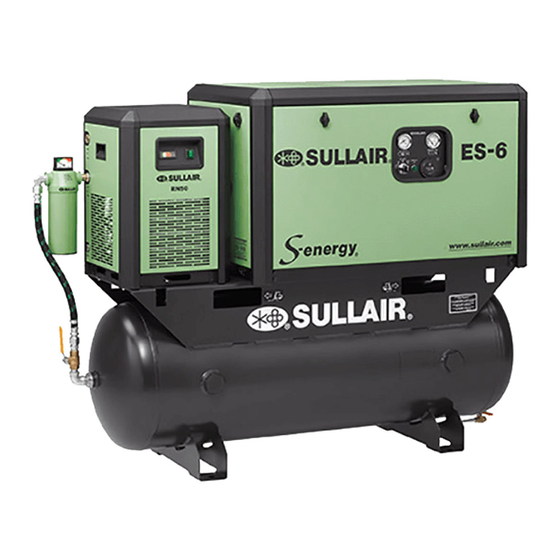
- Page 1 ROTARY SCREW AIR COMPRESSOR ES- -6 Series 5, 7.5 and 10HP 4, 5.5 and 7.5 kw OPERATOR’S MANUAL AND PARTS LIST KEEP FOR FUTURE REFERENCE Part Number 02250057- -634 ©S ullair C or por at ion...
- Page 2 AIR CARE SEMINAR TRAINING Sullair Air Care Seminars are 3--day courses that provide hands--on instruction in the proper operation, maintenance and service of Sullair equipment. Individual seminars on Industrial compressors and compressor electrical systems are presented at regular intervals throughout the year at a dedicated training facility at Sullair’s corporate headquarters in Michigan City, Indiana.
-
Page 3: Table Of Contents
TABLE OF CONTENTS Section 1 PAGE SAFETY 1.1 G EN ER AL 1.2 PERSO NAL PROTECTIVE EQUIPMENT 1.3 PRESSURE RELEASE 1.4 FIRE AND EXPLOSION 1.5 MOVING PARTS 1.6 HOT SURFACES, SHARP EDGES AND SHARP CORNERS 1.7 TOXIC AND IRRITATING SUBSTANCES 1.8 ELECTRICAL SHOCK 1.9 LIFTING 1.10 ENTRAPMENT... - Page 4 TABLE OF CONTENTS (CONTINUED) Section 5 PAGE OPERATION 5.1 GENERAL 5.2 PURPOSE OF CONTROLS 5.3 INITIAL START- -UP PROCEDURE 5.4 SUBSEQUENT START- -UP PROCEDURE 5.5 SHUTDOWN PROCEDURE Section 6 MAINTENANCE 6.1 GENERAL 6.2 DAILY OPERATION 6.3 MOTOR BEARING LUBRICATION 6.4 FLUID FILTER MAINTENANCE 6.5 COOLER MAINTENANCE 6.6 PARTS REPLACEMENT MAINTENANCE AND ADJUSTMENT PROCEDURES...
- Page 5 TABLE OF CONTENTS (CONTINUED) Section 7 PAGE ILLUSTRATIONS AND PARTS LIST (CONT) 7.14 WYE- -DELTA ELECTRIC BOX ES- -6 7.15 DECAL GROUP 7.16 WIRING DIAGRAM (SINGLE PHASE) (60 Hz) 7.17 WIRING DIAGRAM (THREE PHASE) (60 Hz) 7.18 WIRING DIAGRAM (50 Hz) 7.19 WIRING DIAGRAM (50 Hz) WYE- -DELTA...
- Page 6 NOTES...
-
Page 7: Personal Protective Equipment
SAFETY 1.1 GENERAL 1926.302(b)(7) and/or any applicable Federal, Sullair Corporation and its subsidiaries design and State and Local codes, standards and regulations. manufacture all of their products so they can be op- B. When the hose is to be used to supply a manifold, erated safely. -
Page 8: Moving Parts
Section 1 SAFETY mulate on, under or around acoustical material, or E. Make sure all personnel are out of and/or clear of on any external surfaces of the air compressor or on the compressor prior to attempting to start or oper- internal surfaces of the enclosure. -
Page 9: Electrical Shock
Section 1 SAFETY G. If air line anti--icer system antifreeze compound by slings instead. In any event, lift and/or handle enters the eyes or if fumes irritate the eyes, they only in full compliance with OSHA standards 29 should be washed with large quantities of clean wa- CFR 1910 subpart N and/or any applicable Federal, ter for fifteen minutes. -
Page 10: Entrapment
Section 1 SAFETY 1.10 ENTRAPMENT A. If the compressor enclosure, if any, is large enough to hold a man and if it is necessary to enter it to perform service adjustments, inform other per- sonnel before doing so, or else secure and tag the access door in the open position to avoid the possi- bility of others closing and possibly latching the door with personnel inside. -
Page 11: Introduction
This re- tions arise which cannot be answered in the follow- placeable filter element contains a built--in bypass ing text, call your nearest Sullair office or the Sullair valve. Under conditions of restricted flow through Corporation Service Department. - Page 12 Section 2 DESCRIPTION Figure 2- -1 Description of Components (4KW) (5.5 & 7.5KW) AIR/FLUID SEPARATOR ELEMENT ACCESS COVER FLUID FILL PLUG FLUID FILTER ELEMENT COMPRESSOR FLUID FLUID LEVEL DRAIN CAP SIGHT GLASS FLUID FILL PLUG COMPRESSOR FLUID DRAIN CAP...
-
Page 13: Control System, Functional Description
Section 2 DESCRIPTION Figure 2- -2 Encapsulated Compressor System 2.6 CONTROL SYSTEM, FUNCTIONAL DE- the pressure switch, the pressure switch closes, re-- SCRIPTION energizing the normally open solenoid valve and al- The purpose of the compressor control system is to lowing the compressor to load again. -
Page 14: Instrumentation, Functional Description
2.7 INSTRUMENTATION, FUNCTIONAL NOTE SCRIPTION Due to the simplicity of the ES--6 Series compres- At compressor shutdown, the sump pressure is sor, the only instrumentation necessary is a line released to atmosphere through the solenoid pressure gauge which is located on the left side of valve. - Page 15 Nominal 3/16” x 3/16” x 1 1/4” FLUID FILTER Type: Spin on, Sullair Proprietary Micron: 23 Microns Abs. Internal Bypass Valve Set at 25 psig FLUID SEPARATOR ELEMENT Type: Push In Cartridge, Sullair Proprietary Efficiency at Maximum Capacity: 5PPM Maximum...
-
Page 16: Compressor Lubrication Guide
Sullair for recommendation. Adopted January 19, 1972. Maintenance of all other components is still recom- Sullair encourages the user to participate in a fluid mended as indicated in the Operator’s Manual. analysis program. This could result in a fluid change... -
Page 17: Location Of Compressor
INSTALLATION 4.1 LOCATION OF COMPRESSOR joints. Certain other plastic materials may also be affected. The ES--6 Series compressor package may be (I) Plastic Pipe Institute, Recommendation B, Adopted January placed on any level surface able to support its 19, 1972. -
Page 18: Motor Rotation Direction Check
State, Federal and local electrical codes Wiring diagram for standard compressors is sup- concerning isolation switches, fused disconnects, plied on the inside cover of the Control Center. etc. Sullair provides a wiring diagram for use by the Optional compressor wiring diagrams will vary. - Page 19 OPERATION 5.1 GENERAL service or indicate the beginning of a malfunction. While Sullair has built into this compressor a com- Before starting your Sullair compressor, read this prehensive array of controls and indicators to as- section thoroughly and familiarize yourself with the...
- Page 20 Section 5 OPERATION 5.3 INITIAL START- -UP PROCEDURE System Adjustment in Section 6, Maintenance of The following procedure should be used to make the this manual. initial start--up of the compressor. 8. Observe the operating temperature. If the operat- ing temperature exceeds 200 F (93 C), the cool- 1.
- Page 21 Section 6 MAINTENANCE 6.1 GENERAL 1. Remove the fan guard by removing the four (4) self--tapping screws holding the guard and fan ring to the cooler. WARNING 2. Remove the 1/8” NPT plugs in the filler and drain connection for both bearings. Before doing compressor maintenance, discon- 3.
- Page 22 PERIOD (HRS.) PERIOD (HRS.) - -10 F to +90 F Sullube 32 8000 * 8000 * 4000 ** (- -23 C to +32 C) Sullair LLL- -4- -32 8000 * 8000 * 4000 ** SRF 1/4000 4000 4000 4000 **...
- Page 23 Section 6 MAINTENANCE ELEMENT INSPECTION Figure 6- -2 Air Filter (P/N 250025- -421) 1. Place a bright light inside the element to inspect for damage or leak holes. Concentrated light will shine through the element and locate any holes. 2. Inspect all gaskets and gasket contact surfaces of the housing.
- Page 24 Section 6 MAINTENANCE 4. Remove the screw holding the check valve seat. Figure 6- -4 Minimum Pressure/Check Valve Replace valve seat. Reinstall securing with Loc- (P/N 606058) titeR #222. 5. Install new o--ring. Before reinstallation, lubricate with Parker Super “O” ring seal or an equivalent grease.
- Page 25 Section 6 MAINTENANCE Figure 6- -6 Air Pressure Switch (P/N 250025- -299) CONTROL SYSTEM ADJUSTMENT DANGER Ref er t o F igur e 6 -- 6. A ll c om ponent s in t he Cont r ol System are designed and manufactured to close tol- DO NOT touch the electrical contacts, terminal or erances to eliminate any need for adjustments.
- Page 26 Section 6 MAINTENANCE COIL REPLACEMENT 6. Remove socket head capscrew, washers, and 1. Remove the retaining cap, nameplate and cover. check spring from intake valve rod. 2. Slip the yoke containing the coil and sleeves off 7. Remove intake valve from valve housing. Re- the solenoid base subassembly.
- Page 27 Should your problem persist after making the rec- lems. However DO NOT assume that these are the ommended check, consult your nearest Sullair rep- only problems that may occur. All available data resentative or the Sullair Corporation factory.
- Page 28 Section 6 MAINTENANCE TROUBLESHOOTING SYMPTOM PROBABLE CAUSE REMEDY LI N E P R E S S U R E R I S E S A B O V E D ef ec t iv e S olenoid Valv e R epair s olenoid v alv e ( s ee S ec t ion 6) .
- Page 29 Section 6 MAINTENANCE 6.8 MAINTENANCE RECORD MODEL NO. SERIAL NO. AUTHORIZED MAINTENANCE WORK PERFORMED DATE HOURMETER PERFORMED...
- Page 30 Section 7 ILLUSTRATIONS AND PARTS LIST ES- -6 COMPRESSOR ASSEMBLY, EXPLODED VIEW (5.5 AND 7.5KW)
- Page 31 Lading for the compressor or from the Serial Number Plate located on the compressor. The genuine Sullair service parts listed meet or exceed the demands of this compressor. Use of replacement parts other than those approved by Sullair Corporation may lead to hazardous conditions over which Sullair Corporation has no control.
- Page 32 Section 7 ILLUSTRATIONS AND PARTS LIST 7.3 FLUID MANAGEMENT SYSTEM...
- Page 33 Section 7 ILLUSTRATIONS AND PARTS LIST 7.3 FLUID MANAGEMENT SYSTEM part number description number quantity element, fluid filter (I) 250026--982 adapter, fluid filter 250025--914 cap, separator element 250026--038 o--ring, 2 3/16” x 3/32” 826502--139 element, separator air/fluid (II) 250025--264 o--ring, 1 7/16” x 1/16” 826502--127 plug, hex head 1 1/16”--12 SAE 250039--359...
- Page 34 Section 7 ILLUSTRATIONS AND PARTS LIST 7.4 INLET FILTER...
- Page 35 Section 7 ILLUSTRATIONS AND PARTS LIST 7.4 INLET FILTER part number description number quantity filter, air assembly 250025--265 nut, wing 1/4”--20 824815--004 washer, seal 250025--661 hood, air filter 250025--422 element, air filter (I) 250025--421 plate, air filter base 250025--423 rod, threaded 1/4” x 5” 843504--050 (I) For maintenance on air filter element no.
- Page 36 Section 7 ILLUSTRATIONS AND PARTS LIST 7.5 SEAL AND DRIVE GEAR...
- Page 37 Section 7 ILLUSTRATIONS AND PARTS LIST 7.5 SEAL AND DRIVE GEAR part number description number quantity plate, inlet 250028--339 gear, driven Consult Factory gear, drive Consult Factory sleeve, wear 250025--412 seal, shaft Teflon/Viton (I) 250039--218 capscrew, ferry head 1/4”--20 x 3/4” 828404--075 housing, shaft seal 250025--312...
- Page 38 Section 7 ILLUSTRATIONS AND PARTS LIST 7.6 MOTOR, HOUSING AND PARTS 7.5 & 10HP (5.5 & 7.5KW) ONLY...
- Page 39 Section 7 ILLUSTRATIONS AND PARTS LIST 7.6 MOTOR, HOUSING AND PARTS part number description number quantity housing, drive 250026--839 Shousing, drive (metric) 02250059--246 screw, machine round head #8--32 x 1/2” 250030--547 washer, pl--b #8 837201--045 seat, minimum pressure/check valve 250030--223 stem, minimum pressure/check valve 250030--502 spring, minimum pressure/check valve...
- Page 40 Section 7 ILLUSTRATIONS AND PARTS LIST 7.7 COMPRESSOR COOLER SYSTEM 7.5 & 10HP (5.5 & 7.5KW) COOLER...
- Page 41 Section 7 ILLUSTRATIONS AND PARTS LIST 7.7 COMPRESSOR COOLER SYSTEM part number description number quantity duct, cooler mount (5HP/4KW) 250026--472 Sduct, cooler mount (7.5HP and 10HP/5.5 and 7.5KW) 250026--471 ring, cooler (5HP/4KW) 250034--535 Sring, cooler (7.5HP and 10HP/5.5 and 7.5KW) 250034--536 screw, hex serrated washer 1/4”--20 x 1/2”...
- Page 42 Section 7 ILLUSTRATIONS AND PARTS LIST 7.8 COMPRESSOR SYSTEM...
- Page 43 Section 7 ILLUSTRATIONS AND PARTS LIST 7.8 COMPRESSOR SYSTEM part number description number quantity washer seal bolt bu ss 499065--007 locknut, male--M25 x 1 02250055--135 wavespring, male 02250047--887 bearing, taper 499080--203 housing, stator ES--6 “E” profile 250029--910 cover, outlet 250025--315 capscrew, ferry head 1/4”--20 x 11/4”...
- Page 44 Section 7 ILLUSTRATIONS AND PARTS LIST 7.9 INLET CONTROL...
- Page 45 Section 7 ILLUSTRATIONS AND PARTS LIST 7.9 INLET CONTROL part number description number quantity rod, ES--6 intake control valve 02250044--810 spring, PTO ES--6 intake check 250034--619 retainer, ES--6 intake control valve 02250044--809 gasket, inlet valve 250025--425 head, ES--6 intake control valve 02250044--808 housing, intake control 250025--310...
- Page 46 Section 7 ILLUSTRATIONS AND PARTS LIST 7.10 CONTROL BOX...
- Page 47 90 m swvl 1/8T x 1/8 NPT 250025--849 pushbutton, “manual/reset” 02250045--011 screw, 1/4”--20 x 1/2” long 250030--162 fastener, suregrip 041516 nameplate, Sullair 1” x 6” 250035--063 joint, compression phase 230V, 3PH 250026--615 Sphase 3 460V (not shown) 250026--615 insulator, splice phase 1 230V, 3PH 250006--110...
- Page 48 Section 7 ILLUSTRATIONS AND PARTS LIST 7.10 CONTROL BOX...
- Page 49 Section 7 ILLUSTRATIONS AND PARTS LIST 7.10 CONTROL BOX (continued) part number description number quantity bushing, reducing 1/4” x 1/8” 807600--005 switch, pressure 0--200# (air) 250025--299 connector, 1/2” 250026--153 plate ES--6, switch (Ref.) 250031--869 capscrew, hex 1/4”--20 x 5 1/2” 5HP single phase 828604--550 capacitor, run 5HP/4KW single phase...
- Page 50 Section 7 ILLUSTRATIONS AND PARTS LIST 7.11 CANOPY AND PARTS...
- Page 51 ES--6 canopy 250032--309 bracket, ES--6 canopy mounting -- left 250033--701 bracket, canopy ES--6 mounting -- right 250033--702 canopy, stop ES--6 250033--096 decal, Sullair logo (not shown) 02250059--052 decal, ES--6 Model (not shown) 02250060--043 decal, warning--under pressure 02250078--001 decal, prohibit breath 02250078--007...
- Page 52 Section 7 ILLUSTRATIONS AND PARTS LIST 7.12 FRAME, CANOPY AND PARTS...
- Page 53 Section 7 ILLUSTRATIONS AND PARTS LIST 7.12 FRAME, CANOPY AND PARTS part number description number quantity canopy, ES--6 250031--542 pan, ES--6 canopy base 250031--545 partition, ES--6 canopy 250031--546 rod, ES--6 canopy support 250032--223 footing, ES--6 canopy 250032--226 rod, ES--6 canopy hinge 250032--308 soundcoat, ES--6 canopy partition 250032--873...
-
Page 54: Wye- -Delta Electric Box
Section 7 ILLUSTRATIONS AND PARTS LIST 7.13 WYE- -DELTA ELECTRIC BOX ES- -6 DISCHARGE TEMP. LINE PRESSURE POWER ON OFF/RESET AUTO MANUAL R E S E T... - Page 55 Section 7 ILLUSTRATIONS AND PARTS LIST 7.13 WYE- -DELTA ELECTRIC BOX ES- -6 part number description number quantity hose, nylon 1/4” 842215--004 5 ft. valve, solenoid 250030--164 nipple, chase 1/2” 847815--050 box, electric control (5.5 HP/4KW) 250031--242 Sbox, electric control (7.5&10HP/5.5&7.5KW) 250031--243 hourmeter 250042--010...
- Page 56 Section 7 ILLUSTRATIONS AND PARTS LIST 7.14 WYE- -DELTA ELECTRIC BOX ES- -6...
- Page 57 Section 7 ILLUSTRATIONS AND PARTS LIST 7.14 WYE- -DELTA ELECTRIC BOX ES- -6 part number description number quantity tee, tube 250028--270 connector, liquid tight 250041--988 connector, male 1/4” x 1/8” 250025--858 terminal, block Consult Factory fuse, 2 amp Consult Factory Sfuse, carrier Consult Factory Sfuse, 4 amp...
-
Page 58: Decal Group
Section 7 ILLUSTRATIONS AND PARTS LIST 7.15 DECAL GROUP... - Page 59 (not shown) 02250077--999 decal, warning auto start (not shown) 02250077--473 decal, prohibition, breath/food (not shown) 02250078--998 decal, Sullair logo (not shown) 02250059--052 decal, rotation direction 040745 decal, compressor fluid Sullube 32 (I) 02250069--389 decal, fluid SRF 1/4000 (not shown) (I) 02250069--391...
- Page 60 Section 7 ILLUSTRATIONS AND PARTS LIST 7.15 DECAL GROUP...
- Page 61 Section 7 ILLUSTRATIONS AND PARTS LIST 7.15 DECAL GROUP (continued) part number description number quantity decal, ES--6 canopy bezel 02250061--884 decal, mandatory read manual (not shown) 02250078--002 PLEASE NOTE: WHEN ORDERING PARTS, INDICATE SERIAL NUMBER OF COMPRESSOR...
-
Page 62: Wiring Diagram (Single Phase) (60Hz)
Section 7 ILLUSTRATIONS AND PARTS LIST 7.16 WIRING DIAGRAM (SINGLE PHASE) (60Hz) -
Page 63: Wiring Diagram (Three Phase) (60Hz)
Section 7 ILLUSTRATIONS AND PARTS LIST 7.17 WIRING DIAGRAM (THREE PHASE) (60Hz) -
Page 64: Wiring Diagram (50 Hz)
Section 7 ILLUSTRATIONS AND PARTS LIST 7.18 WIRING DIAGRAM (50 Hz) -
Page 65: Wiring Diagram (50 Hz) Wye- -Delta
Section 7 ILLUSTRATIONS AND PARTS LIST 7.19 WIRING DIAGRAM (50 Hz) WYE- -DELTA... - Page 66 NOTES...
- Page 67 NOTES...
- Page 68 SULLAIR CORPORATION Subsidiary of Sundstrand Corporation 3700 East Michigan Boulevard Michigan City, Indiana 46360 U.S.A. Telephone: 1- -800- -SULLAIR (U.S.A. Only) or 1- -219- -879- -5451 Fax: (219) 874 - - 1273 Fax: (219) 874 - - 1835 (Parts) Fax: (219) 874 - - 1805 (Service) Printed in U.S.A.
Need help?
Do you have a question about the ES--6 Series and is the answer not in the manual?
Questions and answers
Can you stack these units one on top of the other and if so what should the clearance be between the two?