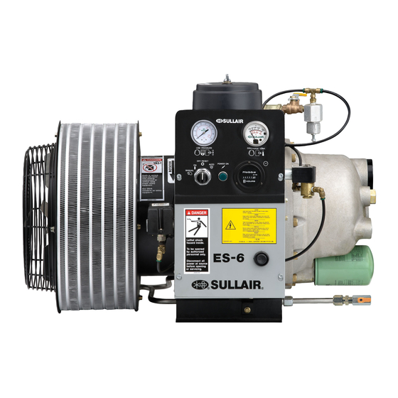
Sullair ES-6 Series User Manual
Standard&24kt 5, 7.5 and 10hp/4, 5.5 and 7.5 kw
Hide thumbs
Also See for ES-6 Series:
- Operator's manual and parts list (68 pages) ,
- User manual (58 pages) ,
- Operators manual and parts lists (55 pages)
Table of Contents
Advertisement
Advertisement
Table of Contents

Related Manuals for Sullair ES-6 Series


Summary of Contents for Sullair ES-6 Series
- Page 2 AIR CARE SEMINAR TRAINING Sullair Air Care Seminars are courses that provide hands-on instruction for the proper operation, maintenance, and servicing of Sullair products. Individual seminars on Industrial compressors and compressor electrical systems are offered at regular intervals throughout the year at Sullair’s corporate headquarters training facility located at Michigan City, Indiana.
-
Page 3: Table Of Contents
TABLE OF CONTENTS SECTION 1—SAFETY GENERAL PERSONAL PROTECTIVE EQUIPMENT PRESSURE RELEASE FIRE AND EXPLOSION MOVING PARTS HOT SURFACES, SHARP EDGES AND SHARP CORNERS TOXIC AND IRRITATING SUBSTANCES ELECTRICAL SHOCK LIFTING 1.10 ENTRAPMENT SECTION 2—DESCRIPTION INTRODUCTION DESCRIPTION OF COMPONENTS ENCAPSULATED COMPRESSOR SYSTEM, FUNCTIONAL DESCRIP- TION COMPRESSOR COOLING SYSTEM FUNCTIONAL DESCRIPTION AIR INLET SYSTEM, FUNCTIONAL DESCRIPTION... - Page 4 TABLE OF CONTENTS 3.10 IDENTIFICATION, ES-6 ENCLOSED TANK MOUNT (80 GALLONS) WITH DRYER 3.11 IDENTIFICATION, ES-6 OPEN TANK MOUNT (120 GALLON) 3.12 IDENTIFICATION, ES-6 ENCLOSED TANK MOUNT (120 GALLON) 3.13 IDENTIFICATION, ES-6 OPEN TANK MOUNT (120 GALLON) WITH DRYER 3.14 IDENTIFICATION, ES-6 ENCLOSED TANK MOUNT (120 GALLON) WITH DRYER 3.15...
- Page 5 TABLE OF CONTENTS SECTION 7—PARTS LIST PROCEDURE FOR ORDERING PARTS RECOMMENDED SERVICE PARTS LIST...
- Page 6 TABLE OF CONTENTS...
-
Page 7: Section 1-Safety
GENERAL tions relative to personal protective equipment, such as eye and face protective equipment, Sullair Corporation and its subsidiaries design and respiratory protective equipment, equipment manufacture all of their products so they can be intended to protect the extremities, protective operated safely. -
Page 8: Fire And Explosion
SECTION 1 inside diameter to reduce pressure in case of accumulate on, under or around acoustical mate- hose failure. rial, or on any external surfaces of the air com- pressor. Wipe down using an aqueous industrial D. Flow-limiting valves are listed by pipe size and cleaner or steam clean as required. -
Page 9: Hot Surfaces, Sharp Edges And Sharp Corners
SECTION 1 C. Wear snug-fitting clothing and confine long hair when working around this compressor, especially DANGER when exposed to hot or moving parts. D. Keep access doors, if any, closed except when making repairs or adjustments. E. Make sure all personnel are out of and/or clear of the compressor prior to attempting to start or operate it. -
Page 10: Electrical Shock
SECTION 1 swallowed, induce vomiting by administering a tablespoon of salt, in each glass of clean, warm water until vomit is clear, then administer two DANGER teaspoons of baking soda in a glass of clean water. Have patient lay down and cover eyes to exclude light. -
Page 11: 1.10 Entrapment
SECTION 1 Keep lift operator in constant attendance when- N. Make sure pallet-mounted compressors are ever compressor is suspended. firmly bolted or otherwise secured to the pallet prior to attempting to forklift or transport them. J. Set compressor down only on a level surface NEVER attempt to forklift a compressor that is capable of safely supporting at least its weight not secured to its pallet, as uneven floors or sud-... - Page 12 NOTES...
-
Page 13: Introduction
DO NOT remove caps, plugs and/or other questions arise which cannot be answered in the components when compressor is running following text, call your nearest Sullair office or the or pressurized. Stop compressor and Sullair Corporation Service Department. relieve all internal pressure before doing so. - Page 14 ES-6 USER MANUAL SECTION 2 the replaceable fluid filter element. This replaceable OTOR RIVE ECTION filter element contains a built-in bypass valve. Under The motor/drive section consists of a squirrel cage conditions of restricted flow through the element, the induction motor and integrated drive gearing which is bypass valve helps ensure adequate compressor separated from the motor by a replaceable shaft fluid flow, as well as helps prevent element failure.
- Page 15 SECTION 2 ES-6 USER MANUAL Figure 2-1: Description of Components 1. Air Inlet System 9. Fluid Level Sight Glass 2. Pressure Regulator 10. Encapsulated Compressor System 3. Pressure Gauge 11. Pressure Relief Valve 4. Discharge Temp Gauge 12. Cooling System 5.
-
Page 16: Compressor Cooling System Functional Description
ES-6 USER MANUAL SECTION 2 Figure 2-2: Encapsulated Compressor System 1. Aftercooler and Fluid Cooler 7. Pressure Relief Valve 2. Compressor Unit 8. Discharge Air 3. Fluid Fill Plug 9. Air 4. Fluid Filter 10. Air/Fluid 5. Fluid Level Sight Glass 11. -
Page 17: Control System, Functional Description
The compressor will Due to the simplicity of the ES-6 Series compressor, continue to run (unloaded) until the line pressure the only instrumentation necessary is a line pressure... - Page 18 NOTES...
-
Page 19: Table Of Specifications
ES-6 USER MANUAL Section 3 SPECIFICATIONS TABLE OF SPECIFICATIONS Table 3-1: 60 Hz Model DIMENSIONS dBA (I) with Cap. Max. canopy / Length (II) Width (III) Height (IV) Weight (V) ACFM Pressure without MODEL HP/KW /Min PSIG/BAR canopy ES-6 5H 18/.51 125/8.6 68/80... -
Page 20: Compressor Lubrication Guide
Spin on, Sullair Proprietary Micron: 23 Microns Abs. Table 3-6: Fluid Separator Element Type: Push In Cartridge, Sullair Proprietary Efficency at Maximum Capacity: 3PPM Maximum compressor is factory filled with Sullube, a long life lubricant, unless a different lubricant is requested. -
Page 21: Lubrication Guide - 24Kt Compressors
Sullair 24KT compressors are filled with a lubricant should be used. which rarely needs to be changed. In the event a change of fluid is required, use only Sullair 24KT fluid. CAUTION Mixing of other fluids within the compres- CAUTION sor will void all warranties. -
Page 22: Lubrication Guide - Optional Fluid
ES-6 USER MANUAL SECTION 3 LUBRICATION GUIDE - OPTIONAL FLUID Sullair compressors may use SRF 1/4000 fluid as an optional factory fill. CAUTION Mixing of other fluids within the compres- sor will void all warranties. SRF 1/4000 fluid should be changed every 4000 hours or once a year, whichever comes first. - Page 23 NOTES...
-
Page 24: Identification, Es-6 Standard Without Enclosure
IDENTIFICATION, ES-6 STANDARD WITHOUT ENCLOSURE 02250172-315 R00... - Page 25 IDENTIFICATION, ES-6 STANDARD WITHOUT ENCLOSURE Model DIM ‘A’ APPROX. WT. 5 HP 29.5 230 LBS. 7.5 HP 31.5 270 LBS. 10 HP 31.5 280 LBS. NOTES: 1. ALLOW 4’ MINIMUM CLEARANCE AROUND MACHINE FOR ACCESS AND FREE CIRCULATION OF AIR. 2.
-
Page 26: Identification, Es-6 Standard With Enclosure
IDENTIFICATION, ES-6 STANDARD WITH ENCLOSURE 02250172-316 R00... - Page 27 IDENTIFICATION, ES-6 STANDARD WITH ENCLOSURE Model APPROX. WT. 5 HP 400 LBS. 7.5 HP 440 LBS. 10 HP 450 LBS. NOTES: 1. ALLOW 4’ MINIMUM CLEARANCE AROUND MACHINE FOR ACCESS AND FREE CIRCULATION OF AIR. 2. A FOUNDATION OR MOUNTING CAPABLE OF SUPORTING THE WEIGHT OF PACKAGE, AND RIGID ENOUGH TO MAIN- TAIN THE COMPRESSOR FRAME LEVEL IS REQUIRED.
-
Page 28: Identification, Es-6 Open Tank Mount (80 Gallon)
IDENTIFICATION, ES-6 OPEN TANK MOUNT (80 GALLON) 02250170-490 R00... - Page 29 IDENTIFICATION, ES-6 OPEN TANK MOUNT (80 GALLON) MACHINE WEIGHT 5 HP 560 LBS. 7.5 HP 600 LBS. 10 HP 610 LBS. NOTES: 1. ALLOW 4’ MINIMUM CLEARANCE AROUND MACHINE FOR ACCESS AND FREE CIRCULATION OF AIR. 2. A FOUNDATION OR MOUNTING CAPABLE OF SUPORTING THE WEIGHT OF PACKAGE, AND RIGID ENOUGH TO MAIN- TAIN THE COMPRESSOR FRAME LEVEL IS REQUIRED.
-
Page 30: Identification, Es-6 Enclosed Tank Mount (80 Gallons)
IDENTIFICATION, ES-6 ENCLOSED TANK MOUNT (80 GALLONS) 02250170-491 R00... - Page 31 IDENTIFICATION, ES-6 ENCLOSED TANK MOUNT (80 GALLONS) MACHINE WEIGHT 5 HP 710 LBS. 7.5 HP 750 LBS. 10 HP 760 LBS. NOTES: 1. ALLOW 4’ MINIMUM CLEARANCE AROUND MACHINE FOR ACCESS AND FREE CIRCULATION OF AIR. 2. A FOUNDATION OR MOUNTING CAPABLE OF SUPORTING THE WEIGHT OF PACKAGE, AND RIGID ENOUGH TO MAIN- TAIN THE COMPRESSOR FRAME LEVEL IS REQUIRED.
-
Page 32: Identification, Es-6 Open Tank Mount (80 Gallons) With
IDENTIFICATION, ES-6 OPEN TANK MOUNT (80 GALLONS) WITH DRYER 02250172-307 R00... - Page 33 IDENTIFICATION, ES-6 OPEN TANK MOUNT (80 GALLON) WITH DRYER MACHINE WEIGHT 5 HP 640 LBS. 7.5 HP 680 LBS. 10 HP 690 LBS. NOTES: 1. ALLOW 4’ MINIMUM CLEARANCE AROUND MACHINE FOR ACCESS AND FREE CIRCULATION OF AIR. 2. A FOUNDATION OR MOUNTING CAPABLE OF SUPORTING THE WEIGHT OF PACKAGE, AND RIGID ENOUGH TO MAIN- TAIN THE COMPRESSOR FRAME LEVEL IS REQUIRED.
-
Page 34: Identification, Es-6 Enclosed Tank Mount (80 Gallons
3.10 IDENTIFICATION, ES-6 ENCLOSED TANK MOUNT (80 GALLONS) WITH DRYER 02250172-308 R00... - Page 35 3.10 IDENTIFICATION, ES-6 ENCLOSED TANK MOUNT (80 GALLONS) WITH DRYER MACHINE WEIGHT 5 HP 810 LBS. 7.5 HP 850 LBS. 10 HP 860 LBS. NOTES: 1. ALLOW 4’ MINIMUM CLEARANCE AROUND MACHINE FOR ACCESS AND FREE CIRCULATION OF AIR. 2. A FOUNDATION OR MOUNTING CAPABLE OF SUPORTING THE WEIGHT OF PACKAGE, AND RIGID ENOUGH TO MAIN- TAIN THE COMPRESSOR FRAME LEVEL IS REQUIRED.
- Page 36 3.11 IDENTIFICATION, ES-6 OPEN TANK MOUNT (120 GALLON) 02250172-309 R00...
- Page 37 3.11 IDENTIFICATION, ES-6 OPEN TANK MOUNT (120 GALLON) MACHINE WEIGHT 5 HP 650 LBS. 7.5 HP 690 LBS. 10 HP 700 LBS. NOTES: 1. ALLOW 4’ MINIMUM CLEARANCE AROUND MACHINE FOR ACCESS AND FREE CIRCULATION OF AIR. 2. A FOUNDATION OR MOUNTING CAPABLE OF SUPORTING THE WEIGHT OF PACKAGE, AND RIGID ENOUGH TO MAIN- TAIN THE COMPRESSOR FRAME LEVEL IS REQUIRED.
-
Page 38: Identification, Es-6 Enclosed Tank Mount (120 Gallon
3.12 IDENTIFICATION, ES-6 ENCLOSED TANK MOUNT (120 GALLON) 02250172-310 R00... - Page 39 3.12 IDENTIFICATION, ES-6 ENCLOSED TANK MOUNT (120 GALLON) MACHINE WEIGHT 5 HP 800 LBS 7.5 HP 840 LBS 10 HP 850 LBS NOTES: 1. ALLOW 4’ MINIMUM CLEARANCE AROUND MACHINE FOR ACCESS AND FREE CIRCULATION OF AIR. 2. A FOUNDATION OR MOUNTING CAPABLE OF SUPORTING THE WEIGHT OF PACKAGE, AND RIGID ENOUGH TO MAIN- TAIN THE COMPRESSOR FRAME LEVEL IS REQUIRED.
-
Page 40: Identification, Es-6 Open Tank Mount (120 Gallon) With
3.13 IDENTIFICATION, ES-6 OPEN TANK MOUNT (120 GALLON) WITH DRYER 02250172-311 R00... - Page 41 3.13 IDENTIFICATION, ES-6 OPEN TANK MOUNT (120 GALLON) WITH DRYER MACHINE WEIGHT 5 HP 730 LBS. 7.5 HP 770 LBS. 10 HP 780 LBS. NOTES: 1. ALLOW 4’ MINIMUM CLEARANCE AROUND MACHINE FOR ACCESS AND FREE CIRCULATION OF AIR. 2. A FOUNDATION OR MOUNTING CAPABLE OF SUPORTING THE WEIGHT OF PACKAGE, AND RIGID ENOUGH TO MAIN- TAIN THE COMPRESSOR FRAME LEVEL IS REQUIRED.
- Page 42 3.14 IDENTIFICATION, ES-6 ENCLOSED TANK MOUNT (120 GALLON) WITH DRYER 02250172-312 R00...
- Page 43 3.14 IDENTIFICATION, ES-6 ENCLOSED TANK MOUNT (120 GALLON) WITH DRYER MACHINE WEIGHT 5 HP 800 LBS. 7.5 HP 840 LBS. 10 HP 850 LBS. NOTES: 1. ALLOW 4’ MINIMUM CLEARANCE AROUND MACHINE FOR ACCESS AND FREE CIRCULATION OF AIR. 2. A FOUNDATION OR MOUNTING CAPABLE OF SUPORTING THE WEIGHT OF PACKAGE, AND RIGID ENOUGH TO MAIN- TAIN THE COMPRESSOR FRAME LEVEL IS REQUIRED.
- Page 44 3.15 PIPING AND INSTRUMENTATION DIAGRAM—STANDARD AND WYE-DELTA 02250101-011 R04...
- Page 45 3.15 ID,PIPING AND INSTRUMENTATION DIAGRAM—STANDARD AND WYE-DELTA ITEM DESCRIPTION PART NO. QTY NOTE COSTUMER CONNECTIONS filter, air heavy duty es-6 02250111-679 OPEN MACHINE 1/2’’ NPT valve, air intake sub-assy 606448 motor various ENCLOSED MACHINE 1/2’’ NPT valve, solenoid n.o. 500psi 02250125-655 WITH TANK 1 1/4’’...
- Page 46 3.16 WIRING DIAGRAM—DUAL CONTROL FULL VOLTAGE 2-WIRE 02250045-623 R06...
- Page 47 3.16 ID, WIRING DIAGRAM—DUAL CONTROL FULL VOLTAGE 2-WIRE NOTES: 1. OPTIONAL. 2. REMOVE JUMPER TO ADD OPTION. 3. SEE TRANSFORMER DIAGRAM FOR CORRECT PRIMARY CONNECTIONS. 4. REMOVE JUMPER 6 AND 7; 9 AND 2 WHEN CONNECTING TO BASE LOAD SWITCH.
-
Page 48: Wiring Diagram—Dual Control Full Voltage 3-Wire
3.17 WIRING DIAGRAM—DUAL CONTROL FULL VOLTAGE 3-WIRE 02250062-643 R04... - Page 49 3.17 ID, WIRING DIAGRAM—DUAL CONTROL FULL VOLTAGE 3-WIRE NOTES: 1. OPTIONAL 2. REMOVE JUMPER TO ADD OPTION 3. SEE TRANSFORMER DIAGRAM FOR CORRECT PRIMARY CONNECTIONS.
-
Page 50: Wiring Diagram—Dual Control 200-230/1/60 5 Hp
3.18 WIRING DIAGRAM—DUAL CONTROL 200-230/1/60 5 HP 606512-001 R07... - Page 51 3.18 ID, WIRING DIAGRAM—DUAL CONTROL 200-230/1/60 5 HP NOTES: 1. OPTIONAL 2. P1 AND P2 NOT USED FOR REF. ONLY.
-
Page 52: Wiring Diagram—Dual Control Wye-Delta
3.19 WIRING DIAGRAM—DUAL CONTROL WYE-DELTA 02250058-093 R04... - Page 53 3.19 ID, WIRING DIAGRAM—DUAL CONTROL WYE-DELTA WYE-DELTA 1MOL MOTOR-STARTER OVERLOAD NO CONTACT PRIMARY SECONDARY 1MTR WYE-DELTA TRANSITION TIMER RELAY VOLTS TAPS VOLTS TAPS WYE-DELTA TRANSITION COIL H1-H2 X1-X3 WYE-DELTA START COIL H1-H4 X1-X3 RUN CONTROL RELAY POWER FAILURE RESTART RELAY NOTES: HOURMETER 1.
-
Page 54: Wiring Diagram—Srs 25-100 115-230V/1/60
3.20 WIRING DIAGRAM—SRS 25-100 115-230V/1/60 02250171-733 R00... - Page 55 3.20 ID, WIRING DIAGRAM—SRS 25-100 115-230V/1/60 ELECTRICAL SPECIFICATIONS COMPONENT DESCRIPTION COMPRESSOR - UN 115V 1PH 60HZ FAN MOTOR - UN 115V 1PH 50-60HZ MAIN SWITCH SRS-25 FLA 4.32 0.41KW FLA 0.46 0.035KW ELECTRIC DRAIN POWER SUPPLY SRS-35 FLA 4.32 0.41KW FLA 0.46 0.035KW COMPRESSOR MOTOR SRS-50 FLA 7.31 0.651KW...
-
Page 56: Wiring Diagram—Srs 9-18 220-240V/1/50
3.21 WIRING DIAGRAM—SRS 9-18 220-240V/1/50 02250171-738 R00... - Page 57 3.21 ID, WIRING DIAGRAM—SRS 9-18 220-240V/1/50 COMPONENT DESCRIPTION MAIN SWITCH ELECTRICAL SPECIFICATIONS ELECTRIC DRAIN POWER SUPPLY COMPRESSOR UN 220/240V 1PH 50HZ FAN MOTOR UN 220/240V 1PH 50-60HZ COMPRESSOR MOTOR SRS-30 FLA 4.80 0.880KW FLA 0.23 0.035KW FAN MOTOR SRS-24 FLA 4.16 0.721KW FLA 0.23 0.035KW FAN THERMOSTATIC SWITCH NOTES:...
-
Page 58: Wiring Diagram—Srs 24-30 220-240V/1/50
3.22 WIRING DIAGRAM—SRS 24-30 220-240V/1/50 02250171-739 R00... - Page 59 3.22 ID, WIRING DIAGRAM—SRS 24-30 220-240V/1/50 COMPONENT DESCRIPTION MAIN SWITCH ELECTRICAL SPECIFICATIONS ELECTRIC DRAIN POWER SUPPLY COMPRESSOR UN 220/240V 1PH 50HZ FAN MOTOR UN 220/240V 1PH 50-60HZ COMPRESSOR MOTOR SRS-30 FLA 4.80 0.880KW FLA 0.23 0.035KW FAN MOTOR SRS-24 FLA 4.16 0.721KW FLA 0.23 0.035KW FAN THERMOSTATIC SWITCH NOTES:...
- Page 60 NOTES...
-
Page 61: Location Of Compressor
ES-6 USER MANUAL Section 4 INSTALLATION LOCATION OF COMPRESSOR The ES-6 Series compressor package may be WARNING placed on any level surface able to support its weight. The unit should be bolted to a fixed mounting "The Plastic Pipe Institute recommends... -
Page 62: Motor Rotation Direction Check
State, Federal and local electrical codes concerning isolation switches, fused disconnects, etc. Sullair provides a wiring diagram for use by the installer. A few electrical checks should be made to help assure that the first start-up will be trouble-free. - Page 63 SECTION 4 ES-6 USER MANUAL Figure 4-1: Service Air Piping 1. Optional or Customer Supplied Equipment 2. By pass Valves (I) 3. Dryers 4. Water Leg (II) 5. Pre-Filter 6. Trap 7. Moisture Drain (II) 8. Air Outlets (Never take air from bottom of pipe) (I) Required only when compressor is installed with an air dryer (II) Required for compressor installation without an air dryer.
- Page 64 NOTES turning the selector switch to the manual and automatic positions, and check all protection devices making sure when activated, they NOTE will de-energize the starter control coil. 5. Reconnect the motor leads and jog the Assure that line pressure gauge on com- motor for a direction of rotation check as pressor indicates "ZERO"...
-
Page 65: General
GENERAL for service or indicate the beginning of a malfunction. Before starting your Sullair compressor, read this While Sullair has built into this compressor a section thoroughly and familiarize yourself with the comprehensive array of controls and indicators to controls and indicators - their purpose, location and assure you that it is operating properly, you will want use. -
Page 66: Initial Start-Up Procedure
ES-6 USER MANUAL SECTION 5 INITIAL START-UP essary, see Control System Adjusment in PROCEDURE Section 6: Maintenance. 8. Observe the operating temperature. If the The following procedure should be used to make the operating temperature exceeds 200°F initial start-up of the compressor. (93°C), the cooling system and installation environment should be checked. -
Page 67: General
ES-6 USER MANUAL Section 6 MAINTENANCE GENERAL MOTOR BEARING LUBRICANT WARNING WARNING Before doing compressor maintenance, dis- connect compressor from power source Before doing compressor maintenance, dis- and lock out power source. Isolate com- connect compressor from power source pressor from line pressure by closing rec- and lock out power source. -
Page 68: Fluid Filter Maintenance
ES-6 USER MANUAL SECTION 6 Table 6-1: Motor Bearing Lubrication Schedule Model Standard Conditions (I) Severe Conditions (II) Extreme Conditions (III) 5HP (4KW) 3 Years 1 Year 6 Months 7.5 and 10HP 2.5 Years 10.5 Months 5.5 Months (5.5 & 7.5 KW) All Motors Over 6 Months 3 Months... -
Page 69: Parts Replacement And Adjustment Procedures
SECTION 6 ES-6 USER MANUAL PARTS REPLACEMENT AND 2. Drain fluid by removing fluid drain valve cap ADJUSTMENT at tee located beneath compressor (for com- PROCEDURES plete fluid change, drain fluid from cooler). 3. Using a strap wrench, remove the old ele- ment and gasket. - Page 70 ES-6 USER MANUAL SECTION 6 WARNING WARNING Before doing compressor maintenance, Before doing compressor maintenance, disconnect compressor from power source disconnect compressor from power source and lock out power source. Isolate and lock out power source. Isolate compressor from line pressure by closing compressor from line pressure by closing recommended discharge shut-off valve and recommended discharge shut-off valve and...
- Page 71 SECTION 6 ES-6 USER MANUAL INIMUM RESSURE HECK ALVE AINTENANCE Refer to Figure 6-4. Minimum pressure/check valve maintenance is minimal. The only parts which normally require replacement are the o-ring seal around the piston and the valve seat on the check valve.
- Page 72 NOTES 6. Install new actuator. 4. Observe the line pressure gauge and pres- sure switch contacts. When the line pressure 7. Install piston and spring with centering guide. reaches nameplate pressure, the pressure 8. Re-install plug. switch contacts should open. 9.
- Page 73 SECTION 6 ES-6 USER MANUAL IFFERNTIAL DJUSTMENT OF RESSURE ISASSEMBLY AND EASSEMBLY WITCH 1. Remove the retaining cap and slip the entire Differential is the difference between the high and solenoid off the solenoid base subassembly. low pressure settings. 2. Unscrew solenoid base assembly.
- Page 74 ES-6 USER MANUAL SECTION 6 Figure 6-7: Inlet Control Valve 1. Nylok Screw 4. Intake Valve Head 7. Intake Valve Rod 10. Spring Washers 13. Retaining Ring 2. Piston Seal (I) 5. Spring Retainer 8. Gasket (I) 11. Intake Check Spring 3.
-
Page 75: Troubleshooting
250028-035. Should your problem persist after making the recommended check, consult your nearest Sullair TROUBLESHOOTING representative or the Sullair Corporation factory. The information contained in the Troubleshooting chart is based upon both the actual applied situations and extensive testing at the factory. - Page 76 ES-6 USER MANUAL SECTION 6 TROUBLESHOOTING GUIDE COMPRESSOR WILL NOT BUILD UP Air Demand is Too Great Check service lines for leaks or open FULL DISCHARGE PRESSURE valves. Dirty Air Filter Check filter and change element if required. Pressure Regulator Out Of Adjust- Adjust regulator according to control adjustment instructions in Section 6: ment...
-
Page 77: Maintenance Record
SECTION 6 ES-6 USER MANUAL MAINTENANCE RECORD Model No.____________________ Serial No.____________________________________________ Date: Hour Meter: Maintenance Record: Work Performed By: Authorized By:... - Page 78 NOTES...
- Page 79 Serial Number Plate located on the compressor. See Figure 7-1: Serial Plate Serial Number Location. The genuine Sullair service parts listed meet or exceed the demands of this compressor. Use of replacement parts other than those approved by Sullair Corporation may lead to hazardous conditions over which Sullair Corporation has no control.
- Page 80 RECOMMENDED SERVICE PARTS LIST RECOMMENDED SERVICE PARTS LIST KEY NO. ORDER PART NO. DESCRIPTION NOTE ELEMENTS 250028-032 replacement element kit for fluid filter 250026-982 250028-033 replacement element kit for air/fluid separator 250025-264 02250111-804 replacement element kit for air filter 02250111-680 02250172-109 filter, clean air inlet option es6 KITS...
- Page 81 PARTS LIST KEY NO. ORDER PART NO. DESCRIPTION NOTE FLUIDS 250009-396 fluid, Sullube (one gallon) 250022-669 fluid, Sullube (five gallons) 02250051-153 fluid, 24 KT (5 gallons) 250019-662 fluid, SRF 1/4000 (5 gallons) (I) For proper amount of fluid fill, please consult Table 3-7:Lubrication Guide. CAUTION Mixing of other lubricants within the com- pressor unit will void all warranties.
- Page 82 NOTES...
- Page 83 NOTES...
Need help?
Do you have a question about the ES-6 Series and is the answer not in the manual?
Questions and answers