Sign In
Upload
Download
Table of Contents
Contents
Add to my manuals
Delete from my manuals
Share
URL of this page:
HTML Link:
Bookmark this page
Add
Manual will be automatically added to "My Manuals"
Print this page
×
Bookmark added
×
Added to my manuals
Manuals
Brands
Parker Manuals
Industrial Equipment
732 Series
Owner's manual
Parker 732 Series Owner's Manual
Legacy split shaft and gear box
Hide thumbs
1
2
Table Of Contents
3
4
5
6
7
8
9
10
11
12
13
14
15
16
17
18
19
20
21
22
23
24
25
26
27
28
29
30
31
32
33
34
35
36
page
of
36
Go
/
36
Contents
Table of Contents
Troubleshooting
Bookmarks
Table of Contents
Table of Contents
Contents
General Information
Foreword
Safety Information
Chelsea PTO Safety Label Installation
Direct Mount Pump Support Requirements
Shifting Procedures
Split Shaft and Gear Box Specifications
Horsepower-Torque-RPM Conversion Chart
Installation of a Split Shaft
Application Data
Lubrication Information
Installation Instructions
Installation of a Gear Box
Installation Instructions
Models 700, 712, 721, 732, 741 and 2230
Model 931 Installation Drawings
Model 931 Dimensional Drawings
Breather Hose Installation
Installation of a PTO to a Split Shaft Mounting Instructions 6 or 8-Bolt Applications
Checking Backlash
Wire Shift Pto's and Gear Boxes
Cable Control Installation Instructions
Air Shift Installation Sketch Air Shift Circuit 2230 Series
Dash Drilling Templates Wire and Lever Controls
Indicator Light Installation
Continuity Check
Troubleshooting
Troubleshooting
Power Take-Off Maintenance
Offer of Sale
Advertisement
Quick Links
1
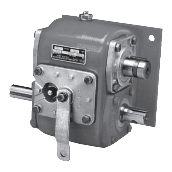
Models 700, 712, 721, 732, 741 and 2230
Download this manual
Effective:
March 2016
Supercedes: HY25-1202-M1/US September 2014
Legacy Split Shaft and Gear Box
Owner's Manual
700, 712, 721, 732, 741, 931, 2230 Series
Table of
Contents
Previous
Page
Next
Page
1
2
3
4
5
Advertisement
Table of Contents
Troubleshooting
Troubleshooting
31
Troubleshooting
32
Need help?
Do you have a question about the 732 Series and is the answer not in the manual?
Ask a question
Questions and answers
Related Manuals for Parker 732 Series
Engine Parker 700 Series Service Procedure
Low speed high torque (21 pages)
Industrial Equipment Parker 712 Series Owner's Manual
Legacy split shaft and gear box (36 pages)
Industrial Equipment Parker 721 Series Owner's Manual
Legacy split shaft and gear box (36 pages)
Industrial Equipment Parker 741 Series Owner's Manual
Legacy split shaft and gear box (36 pages)
Industrial Equipment Parker 341 N Series Installation, Operating, Maintenance
Spool valves (11 pages)
Industrial Equipment Parker ORIGA P120 Series Assembly Instructions Manual
(20 pages)
Industrial Equipment Parker Parflange 1025 Operating Instructions Manual
(118 pages)
Industrial Equipment Parker LORD Use And Maintenance Manual
Axial isolator gen 3.5 (22 pages)
Industrial Equipment Parker V14 Series Spare Parts Manual
(40 pages)
Industrial Equipment Parker Greer BA Series Maintenance Manual
Bladder accumulators (9 pages)
Industrial Equipment Parker HTR Series Maintenance Instructions & Parts List
Htr series hydraulic rack & pinion actuators (4 pages)
Industrial Equipment Parker Helac PowerTilt Series Service And Repair Manual
(60 pages)
Industrial Equipment Parker TH1E-5 Operating Manual
Hose fitting insertion device (24 pages)
Industrial Equipment Parker HTG Series Service Procedure
Integrated hydrostatic transmission (64 pages)
Industrial Equipment Parker KarryFlare Operating Manual
Portable flaring device for triple-lok fittings (13 pages)
Industrial Equipment Parker P1F Manual
Pneumatic cylinders (32 pages)
This manual is also suitable for:
700 series
721 series
712 series
931 series
741 series
2230 series
Table of Contents
Print
Rename the bookmark
Delete bookmark?
Delete from my manuals?
Login
Sign In
OR
Sign in with Facebook
Sign in with Google
Upload manual
Upload from disk
Upload from URL


Need help?
Do you have a question about the 732 Series and is the answer not in the manual?
Questions and answers