
Related Manuals for Parker LORD


Summary of Contents for Parker LORD
- Page 1 LORD Axial Isolator Gen 3.5 Use and Maintenance Manual UM1004 | MRO-00011 05/21 Rev.0 DCO-016875...
-
Page 2: Table Of Contents
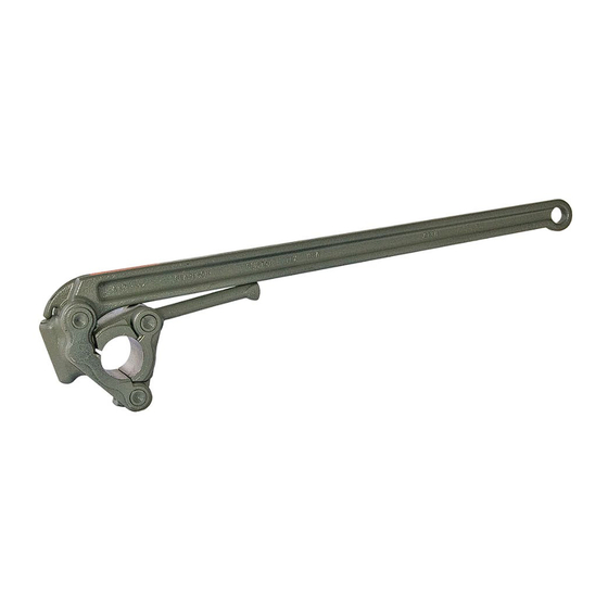
Table of Contents INTRODUCTION ................................ 4 FUNCTION ................................. 4 ASSEMBLY INTO MWD/LWD TOOL STRING ......................4 Mechanical ................................4 Pressure Conduit..............................4 Location in MWD String ............................4 OPERATING PARAMETERS ............................ 5 Maximum Operating Conditions ..........................5 Maximum Static Loads ............................5 Explosive Decompression ............................. - Page 3 Listing of Figures Figure 1: 1-7/8" Friction Wrench ............................4 Figure 2: Axial Isolator Location in MWD String ........................4 Figure 3: J-28348-64 Axial Isolator - Exploded View ......................7 Figure 4: J-28348-64 Axial Isolator External Joints ....................... 8 Figure 5: J-28348-64 Axial Isolator Internal Joints......................... 8 Figure 6: J-28348-64 Shoulder-to-Shoulder Length ......................
-
Page 4: Introduction
INTRODUCTION The patented LORD J-28348-64 MWD Tool Axial Isolator is designed for service in air, foam, or mud drilling operations. Its use and maintenance requirements are summarized in this document. FUNCTION The LORD J-28348-64 MWD Tool Axial Isolator (herein referred to as the Isolator) is designed to protect the sensitive electronics in an MWD string by isolating these components from broad frequency vibrations. -
Page 5: Operating Parameters
Elastomer kits rated for high temperature use are available, please contact your Parker LORD representative for details. The Isolator has no pressure rating limitations as it is pressure compensated with the downhole environment. -
Page 6: Redress Kits
RECOMMENDED SERVICE KIT STOCK Parker LORD recommends that certain service kit items be put in stock by the users of the Isolator to facilitate quick repair or replacement of wear items. This section will detail the recommended kits and quantities that should be kept on hand. -
Page 7: Illustrated Parts List (Ipl)
ILLUSTRATED PARTS LIST (IPL) Figure 3: J-28348-64 Axial Isolator - Exploded View UM1004 | MRO-00011 05/21 Rev.0 DCO-016875... -
Page 8: Field Checks And Maintenance
Joint A Joint B Figure 4: J-28348-64 Axial Isolator External Joints Joint C Joint D Joint E Joint F Figure 5: J-28348-64 Axial Isolator Internal Joints FIELD CHECKS AND MAINTENANCE Service Intervals Maintenance and replacement of key wear items is critical to maintaining performance of the Isolator. Recommended service intervals for the Isolator components are shown in Table 8. -
Page 9: Overall Length (Oal) Inspection [Shoulder-To-Shoulder]
Overall Length (OAL) Inspection [Shoulder-to-Shoulder] The nominal starting length of the Isolator is 36 ± 1/16 inches long when measured shoulder-to-shoulder as shown in Figure 6. Between runs, the length can be checked using the below method. When the OAL falls near or below the minimum, the Isolator requires a full elastomer replacement, Level II Service. -
Page 10: Special Tools
10.2 Special Tools Specialized tools are used to assist in the assembly of the Isolator and are provided directly from LORD. These tools are shown in Table 11. Table 11: Special Tools Tool Number Tool Description Service Level FAS-60530 T-Seal Funnel... -
Page 11: Disassembly
• Replace Items as required due to wear/wash Purchase Axial Elastomer Kit [J-28460-34], and Axial Redress Kit [J-28460-68] to perform Level II Service. 11.2 Disassembly Procedure Secure Outer Housing (Y-63700-104-1) in vise. Remove Sealing Sub Assembly (J-28460-39) from Outer Housing [Joint A]. Loosen, but do not fully remove, Pin Catch (Y-63700-134-2) [Joint C]. - Page 12 Place Anti-Rotation Sub (Y-63700-161-1) in a friction vise (or utilize a friction tong) and remove Threaded Seal Piston (TSP) (Y-63700-58-1) using locking pliers [Joint D]. Remove (4) Elastomer Bonded Compression Stacks (J-28348-53). Utilize open end wrench to remove Tapered Drive Washer (Y-63700-105-1) [Joint E]. Remove (2) Elastomer Bonded Rebound Stacks (J-28348-45).
- Page 13 Utilize 7/8" friction wrench to remove Inner Member (Y-63700-103-1) from Anti-Rotation Sub [Joint F]. 10. Remove Pin Catch (Y-63700-134-2), Guide Band (Y-63700-138-2) and (6) Pins (Y-63700-165-1) [Joint C]. UM1004 | MRO-00011 05/21 Rev.0 DCO-016875...
-
Page 14: Assembly
11.3 Assembly 1. Install Pin Catch (Y-63700-134-2) and Guide Band (Y-63700-138-2) over Anti-Rotation Inner Member (Y-63700-162-1). Apply grease to the (6) pin grooves and install the (6) pins (Y-63700-165-1). UM1004 | MRO-00011 05/21 Rev.0 DCO-016875... - Page 15 Slide Anti-Rotation Sub (Y-63700-161-1) over Anti-Rotation Inner Member (Y-63700-162-1). Apply Kopr Kote on Threads and Hand-tighten Pin Catch (Y-63700-134-2) over Guide Band (Y-63700-138-2) [Joint C]. Apply LOCTITE 243 to Inner Member (Y-63700-103-1). UM1004 | MRO-00011 05/21 Rev.0 DCO-016875...
- Page 16 Install the Anti-Rotation Sub (Y-63700-161-1) in Friction Vise. Install the Inner Member (Y-63700-103-1) into the Anti- Rotation Inner Member (Y-63700-162-1) [Joint F] through the Anti-Rotation Sub (Y-63700-161-1). Kopr-Kote may be added to tip of Inner Member shaft (Y-63700-103-1) to lubricate tapered shoulder for assembly. Use 7/8"...
- Page 17 Joint F can be verified to be fully seated by disconnecting the Pin Catch (Y-63700-134-2) from the Anti- [Optional] Rotation Sub (Y-63700-161-1), fully exposing Joint F. Confirm the undercut/thread relief on Inner Member (Y-63700- 103-1) is 50% exposed. Install (2) Bonded Rebound Stacks (J-28348-45). Apply LOCTITE 243 on center thread of Inner Member (Y-63700-103-1).
- Page 18 10. Install Tapered Drive Washer (Y-63700-105-1) hand tight [Joint E]. Ensure the undercut/thread relief on Inner Member is 50% exposed. 11. Install (4) Bonded Compression Stacks (J-28348-53). 12. Apply LOCTITE 243 or LOCTITE 262 to Threaded Seal Piston (TSP) (Y-63700-58-1). 13.
- Page 19 14. Use FAS-60530 (can be obtained from LORD) to install (2) T-Seals. 15. Secure Outer Housing (Y-63700-104-1) in vise. 16. Insert Assembly into Outer Housing. 17. Torque Pin Catch (Y-63700-134-2) to Anti-Rotation Sub (Y-63700-161-1) with 350 ft-lb [Joint C]. UM1004 | MRO-00011 05/21 Rev.0...
- Page 20 18. Torque Anti-Rotation Sub (Y-63700-161-1) to Outer Housing (Y-63700-104-1) with 350 ft-lb [Joint B]. 19. Apply Dow Corning 111 to TSP, thoroughly covering T-Seals (J-28460-36). 20. Slide TSP with T-Seals into Sealing Sub Body (Y-63700-140-1). Install Sealing Sub Assembly (J-28460-39) to Outer Housing and torque to 350 ft-lb (Y-63700-104-1) [Joint A].
-
Page 21: J-28460-39 Sealing Sub Assembly/Disassembly
11.4 J-28460-39 Sealing Sub Assembly/Disassembly If replacement of the ceramic insert due to damage, or the sealing sub body due to wash or wear is required LORD can disassemble and re-assemble the components if the customer purchases required components. 11.4.1 J-28460-39 Disassembly Disassembly can be accomplished with the FAS-61430, friction vise, arbor press, 1"... - Page 22 Support Center. Information provided herein is based upon tests believed to be reliable. In as much as Parker LORD has no control over the manner in which others may use this information, it does not guarantee the results to be obtained. In addition, Parker LORD does not guarantee the performance of the product or the results obtained from the use of the product or this information where the product has been repackaged by any third party, including but not limited to any product end-user.
Need help?
Do you have a question about the LORD and is the answer not in the manual?
Questions and answers