Table of Contents
Advertisement
Quick Links
Catalog HY10-1630/US
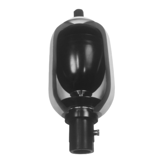
Bladder Accumulators
BLADDER PRODUCTS
Series "BA"
Bladder Accumulators
10 Cu. In. through 40 Gallons
3,000 and 5,000 psi Standard
Bottom and Conventional
Top Repairable
Installation
All accumulators shipped from the factory will be
precharged to a nominal pressure in order to seat the
poppet valve on the hydraulic port. In this case the
precharge will not be listed on the label. However, in
some cases they will be shipped with a nitrogen
charge, the value of which will be marked on the label/
nameplate.
Keep the hydraulic port covered to keep out foreign
material until ready to make the hydraulic connec-
tions.
The accumulator should be mounted within 25° of
vertical with the hydraulic port on the bottom. It should
also be rigidly mounted using appropriate mounting
hardware, which is shown in
the Accumulator Accessories section of this catalog.
The hydraulic circuit, which contains a connection to
the accumulator, should be designed so that it auto-
matically discharges all hydraulic fluid from the
accumulator when the equipment is turned off.
Hydraulic Accumulators
Maintenance Instructions
157
Parker Hannifin Corporation
Hydraulic Accumulator Division
Rockford, Illinois USA
Advertisement
Table of Contents

Subscribe to Our Youtube Channel
Summary of Contents for Parker Greer BA Series
- Page 1 The hydraulic circuit, which contains a connection to the accumulator, should be designed so that it auto- matically discharges all hydraulic fluid from the accumulator when the equipment is turned off. Parker Hannifin Corporation Hydraulic Accumulator Division Rockford, Illinois USA...
- Page 2 Do not reduce precharge by depressing valve core with a foreign object. High pressure may rupture rubber valve seat. † “XX” Denotes to gauge pressure Parker Hannifin Corporation Hydraulic Accumulator Division Rockford, Illinois USA...
- Page 3 For accumulators rated for 3000 psi, either use gaging assembly in is discharging.) Figure 2 (Part #085122XX00) or gaging assembly in Figure 5 (Part #087101XX00) and follow Steps 1 through 7. Remove accumulator from hydraulic system. Parker Hannifin Corporation Hydraulic Accumulator Division Rockford, Illinois USA...
- Page 4 Bladder: Inflate bladder to normal size. Wash bladder with a soap solution. If soap solution bubbles, discard bladder. After 2. Remove jam nut from bladder gas valve stem using a testing, deflate bladder immediately. 1-5/16" socket wrench. Parker Hannifin Corporation Hydraulic Accumulator Division Rockford, Illinois USA...
- Page 5 12. Pre-charge accumulator to desired pressure. See pre- charge instructions. Install accumulator on machine. 9. Install the metal backup, o-ring and o-ring backup. 10. Install the outer spacer. 11. Install the outer locknut. Parker Hannifin Corporation Hydraulic Accumulator Division Rockford, Illinois USA...
- Page 6 L074210005 L074210007 L074210009 Contains items 25 - 40 Gal. 3000 PSI L074400001 L074400003 L074400005 L074400007 L074400009 7, 25 & 26. 1 - 15 Gal. 5000 PSI L074400001 L074400003 L074400005 L074400007 L074400009 Parker Hannifin Corporation Hydraulic Accumulator Division Rockford, Illinois USA...
- Page 7 Hydraulic Accumulators Catalog HY10-1630/US Bladder Accumulators (Parker) Maintenance Instructions Accumulator Parts Description FIGURE A FIGURE B FIGURE C FIGURE D FIGURE E FIGURE F 3000 PSI 3000 PSI 3000 PSI 5000 PSI 5000 PSI 5000 PSI 10 CI -150 CI...
- Page 8 2" SAE Split Flange L074171*03 L074179*03 L074173*03 L074177*03 L074175*03 L074370*03 - 15 Gal. " NPT L074171*04 L074179*04 L074173*04 L074177*04 L074175*04 L074370*04 * = “0” (Std.) Oil Service * = “S” Water/Chem. Service Parker Hannifin Corporation Hydraulic Accumulator Division Rockford, Illinois USA...


Need help?
Do you have a question about the Greer BA Series and is the answer not in the manual?
Questions and answers