Table of Contents
Advertisement
Quick Links
Analysentechnik
Sample gas cooler
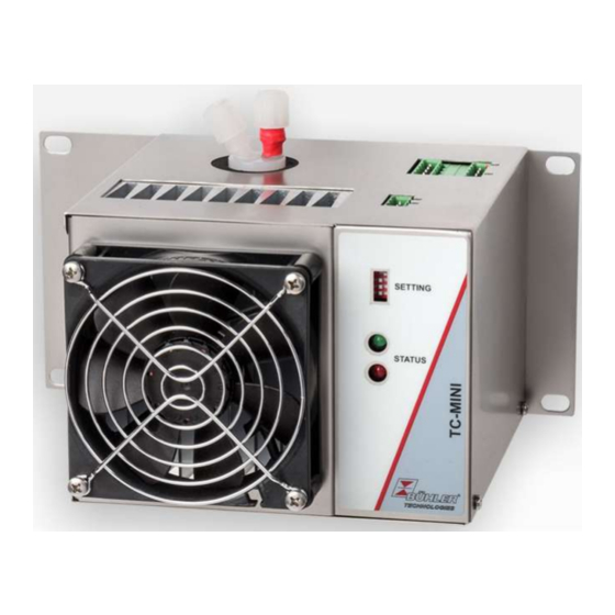
TC-MINI
Installation and Operation Instructions
Original instructions
BE440015
Bühler Technologies GmbH, Harkortstr. 29, D-40880 Ratingen
10/2018
Tel. +49 (0) 21 02 / 49 89-0, Fax: +49 (0) 21 02 / 49 89-20
E-Mail: analyse@buehler-technologies.com
Internet: www.buehler-technologies.com
Advertisement
Table of Contents

Related Manuals for Bühler technologies TC MINI


Summary of Contents for Bühler technologies TC MINI
- Page 1 Analysentechnik Sample gas cooler TC-MINI Installation and Operation Instructions Original instructions BE440015 Bühler Technologies GmbH, Harkortstr. 29, D-40880 Ratingen 10/2018 Tel. +49 (0) 21 02 / 49 89-0, Fax: +49 (0) 21 02 / 49 89-20 E-Mail: analyse@buehler-technologies.com Internet: www.buehler-technologies.com...
- Page 2 Bühler Technologies GmbH, Harkortstr. 29, D-40880 Ratingen Tel. +49 (0) 21 02 / 49 89-0, Fax: +49 (0) 21 02 / 49 89-20 Internet: www.buehler-technologies.com E-Mail: analyse@buehler-technologies.com Read this instruction carefully prior to installation and/or use. Pay at- tention particularly to all advises and safety instructions to prevent in- juries.
-
Page 3: Table Of Contents
TC-MINI Contents Introduction............................................. 2 Intended use ......................................... 2 Types ............................................ 2 Scope of delivery ........................................ 2 Ordering instructions ...................................... 2 Safety instructions......................................... 3 Important advice ......................................... 3 General hazard warnings .................................... 4 Transport and storage ........................................ 5 4 Installation and connection ...................................... 6 Installation site requirements.................................. 6 Installation .......................................... 6 4.2.1... -
Page 4: Introduction
X 0 4 X X X 0 0 X X 1 Product characteristic Gas cooler models (with 1 heat exchanger) TC MINI 6111: moderate ambient temperature 40 °C TC MINI 6112: higher ambient temperature 50 °C Certifications Standard unit, no special certification... -
Page 5: Safety Instructions
TC-MINI 2 Safety instructions 2.1 Important advice Operation of the device is only valid if: – the product is used under the conditions described in the installation- and operation instruction, the intended application according to the type plate and the intended use. In case of unauthorized modifications done by the user Bühler Technolo- gies GmbH can not be held responsible for any damage, –... -
Page 6: General Hazard Warnings
TC-MINI 2.2 General hazard warnings The equipment must be installed by a professional familiar with the safety requirements and risks. Be sure to observe the safety regulations and generally applicable rules of technology relevant for the installation site. Prevent malfunctions and avoid personal injuries and property damage. The operator of the system must ensure: –... -
Page 7: Transport And Storage
TC-MINI 3 Transport and storage Only transport the product inside the original packaging or a suitable alternative. The equipment must be protected from moisture and heat when not in use. It must be stored in a covered, dry and dust-free room at a temperature of -20 °C to 60 °C (-4 °F to 140 °F). -
Page 8: Installation And Connection
TC-MINI 4 Installation and connection 4.1 Installation site requirements The unit is only intended for wall-mounted use in enclosed areas. Adequate protection from the weather must be provided when used outdoors. Install the unit leaving enough room below the cooler to discharge the condensate. Leave room above for the gas supply. Be sure to maintain the approved ambient temperature. -
Page 9: Connecting The Filter Gas Connections (Optional)
TC-MINI 4.2.1 Connecting the filter gas connections (optional) The connection G1/4 or NPT 1/4” (filter head marked NPT) for the gas outlet must be carefully and properly connected using a suitable screw connection. When ordering the cooler with the option filter without Moisture detector, a bypass may be connected to the filter head. The filter head is intended for a G1/4 internal screw thread which is plugged at the factory. - Page 10 TC-MINI X2.1 X2.5 X2.10 X2.6 X1.1 DIP Switch / Settings LED green LED red Inlets/Outputs Terminal Function Description Moisture detector X1.1 FF.1 (white) Moisture detector X1.2 FF.2 (brown) X1.3 Shield for moisture detector inlet Status X2.1 Status NC (Alarm) Alarm / Status X2.2 Status COM Changeover contact, potential-free,...
-
Page 11: Settings
TC-MINI 4.4 Settings Remarks on outlet dew point Not all applications require an outlet dew point of 5 °C. In some applications a higher dew point is sufficient. In other applica- tions a stable outlet dew point doesn’t matter, it’s enough for the gas to be dry, so for the outlet dew point to have an adequate difference in temperature below the ambient temperature. - Page 12 TC-MINI DIP switch The unit is configured using four DIP switches at the front of the cooler. ON switch OFF switch Switch, the following numbering of the SWs corresponds with the numbering on the DIP switch. SW1 / SW2 Gas outlet dew point 3 °C 5 °C (factory preset) 10 °C...
-
Page 13: Operation And Control
TC-MINI 5 Operation and control NOTICE The device must not be operated beyond its specifications. After switching on the supply voltage the cooler starts to cool the cooling block. When switch off the contact between X2.1 and X2.2 is closed. The target temperature is preset to 5 °C at the factory. -
Page 14: Maintenance
TC-MINI 6 Maintenance The basic version of the cooler does not require maintenance. However, it may have different options depending on the configuration ordered. In this case the following maintenance must be performed regularly: Filter option: Check filter element During maintenance, remember: –... -
Page 15: Service And Repair
TC-MINI 7 Service and repair This chapter contains information on troubleshooting and correction should an error occur during operation. Repairs to the unit must be performed by Bühler authorised personnel. Please contact our Service Department with any questions: Tel.: +49-(0)2102-498955 or your agent If the equipment is not functioning properly after correcting any malfunctions and switching on the power, it must be inspected by the manufacturer. -
Page 16: Troubleshooting
TC-MINI 7.1 Troubleshooting Problem / Malfunction Possible Cause Action No LED lights up – Mains voltage interrupted – Connect to mains; check the plug is cor- rectly inserted – Fuse defective – Check fuse and replace if necessary – Defective LED –... -
Page 17: Safety Instructions
TC-MINI 7.2 Safety instructions – The device must be operated within its specifications. – All repairs must be carried out by Bühler authorised personnel only. – Only perform modifications, servicing or mounting described in this manual. – Only use original spare parts. DANGER Toxic, corrosive gas/condensate Sample gas/condensate may be hazardous to health. -
Page 18: Replacing The Filter Element (Option)
TC-MINI 7.5 Replacing the filter element (option) CAUTION Gas leakage The filter should not be dismantled under pressure. Don’t use damaged parts again. – Close the gas supply. – Switch off and unplug the device. – Pull the bracket, holding on to the filter glass. –... -
Page 19: Consumables And Accessories
TC-MINI 7.7.1 Consumables and accessories Item no. Description 91 12 00 00 39 24 V top-hat rail power supply 91 12 00 00 40 24 V top-hat rail power supply for using the 24 V output 45 10 008 Automatic condensate drain AK 5.2 45 10 028 Automatic condensate drain AK 5.5 44 10 004... -
Page 20: Disposal
TC-MINI 8 Disposal The heat exchanger is charged with glycol-based coolant. Dispose of parts so as not to endanger the health or environment. Follow the laws in the country of use for disposing of elec- tronic components and devices as well as hazardous materials during disposal. Bühler Technologies GmbH BE440015 ◦... -
Page 21: Appendices
TC-MINI 9 Appendices 9.1 Gas cooler technical data Gas Cooler Technical Data Ready for operation after max. 10 minutes Ambient temperature 5 °C to 55 °C Gas outlet dew temperature, preset: 5 °C IP rating: IP 20 Housing Stainless steel, brushed Packaging dimensions approx. -
Page 22: Dimensions (Mm)
TC-MINI 9.3 Dimensions (mm) Sample gas IN/OUT Condensate approx. Optional filter 9.4 Performance data A selected outlet dew point of 10 or 15 °C shifts the curves 5 or 10 °C to the right. The MTV and MTG limits apply to a normal operating point of τ = 40 °C and ϑ... -
Page 23: Heat Exchanger
TC-MINI 9.5 Heat exchanger 9.5.1 Heat exchanger description The energy content of the sample gas and the required cooling capacity of the gas cooler is determined by three parameters: gas temperature ϑ , dew point τ (moisture content) and volume flow v. The outlet dew point rises with increasing energy content of the gas. -
Page 24: Attached Documents
TC-MINI 10 Attached documents – Declaration of conformity: KX 440005 – RMA - Decontamination Statement Bühler Technologies GmbH BE440015 ◦ 10/2018...
Need help?
Do you have a question about the TC MINI and is the answer not in the manual?
Questions and answers