Table of Contents
Advertisement
Quick Links
Fluidcontrol
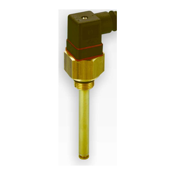
Temperature sensor/switch
TF, TS, Thermolog
Installation and Operation Instructions
Original instructions
BE140006
Bühler Technologies GmbH, Harkortstr. 29, D-40880 Ratingen
04/2022
Tel. +49 (0) 21 02 / 49 89-0, Fax: +49 (0) 21 02 / 49 89-20
E-Mail: fluidcontrol@buehler-technologies.com
Internet: www.buehler-technologies.com
Advertisement
Table of Contents

Related Manuals for Bühler technologies TF-M-PT100-VAL-M3/55


Summary of Contents for Bühler technologies TF-M-PT100-VAL-M3/55
- Page 1 Fluidcontrol Temperature sensor/switch TF, TS, Thermolog Installation and Operation Instructions Original instructions BE140006 Bühler Technologies GmbH, Harkortstr. 29, D-40880 Ratingen 04/2022 Tel. +49 (0) 21 02 / 49 89-0, Fax: +49 (0) 21 02 / 49 89-20 E-Mail: fluidcontrol@buehler-technologies.com Internet: www.buehler-technologies.com...
- Page 2 Bühler Technologies GmbH, Harkortstr. 29, D-40880 Ratingen Tel. +49 (0) 21 02 / 49 89-0, Fax: +49 (0) 21 02 / 49 89-20 Internet: www.buehler-technologies.com E-Mail: fluidcontrol@buehler-technologies.com Read this instruction carefully prior to installation and/or use. Pay at- tention particularly to all advises and safety instructions to prevent in- juries.
-
Page 3: Table Of Contents
TF, TS, Thermolog Contents Introduction ............................................. 2 Intended Use......................................... 2 Scope of Delivery........................................ 2 Model Key MK2/EK2...................................... 2 Model Key TF with Pt100 .................................... 3 Ordering Instructions TF-M-VAL with Pt100 and Spring ......................... 3 Model Key for TSM/TSE...................................... 3 Model Key for TSK........................................ 4 Ordering Instructions TSA.................................... 4 Safety instructions ......................................... -
Page 4: Introduction
TF, TS, Thermolog 1 Introduction 1.1 Intended Use Temperature sensors can be used to monitor the temperature of a fluid within a tank. These operating instructions describe several temperature switches / sensors types in one, as many descriptions identical or similar. -
Page 5: Model Key Tf With Pt100
GS4 (4 lead only) = 4 lead 1.5 Ordering Instructions TF-M-VAL with Pt100 and Spring Item no.: Spring displacement Model 18 92 599 48 - 60 mm TF-M-PT100-VAL-M3/55 18 94 599 206 - 215 mm TF-M-PT100-VAL-M3/210 18 95 799 325 - 334 mm TF-M-PT100-VAL-M3/330 1.6 Model Key for TSM/TSE... -
Page 6: Model Key For Tsk
TF, TS, Thermolog 1.7 Model Key for TSK XX XX G3/4 XX XX T2 (2nd temperature contact) Number of temperature contacts NC contact NO contact 1 or 2 TK40NC TK40NO = 40 °C TK50NC TK50NO = 50 °C Version TK60NC TK60NO = 60 °C Brass... -
Page 7: Safety Instructions
TF, TS, Thermolog 2 Safety instructions 2.1 Important advice Operation of the device is only permitted if: – the product is used under the conditions described in the installation- and operation instruction, the intended application according to the type plate and the intended use. In case of unauthorized modifications done by the user Bühler Technolo- gies GmbH can not be held responsible for any damage, –... -
Page 8: General Hazard Warnings
TF, TS, Thermolog 2.2 General hazard warnings The equipment must be installed by a professional familiar with the safety requirements and risks. Be sure to observe the safety regulations and generally applicable rules of technology relevant for the installation site. Prevent malfunctions and avoid personal injuries and property damage. -
Page 9: Transport And Storage
TF, TS, Thermolog 3 Transport and storage Only transport the product inside the original packaging or a suitable alternative. The equipment must be protected from moisture and heat when not in use. It must be stored in a covered, dry, dust-free room at room temperature. -
Page 10: Setup And Connection
TF, TS, Thermolog 4 Setup and Connection DANGER Toxic, corrosive gasses The sample gas can be harmful to the health if inhaled or on contact. a) Ensure harmful gases are discharged safely. b) Switch off the gas supply before performing maintenance and repairs, and flush the gas lines with air. -
Page 11: Operation And Control
TF, TS, Thermolog 5 Operation and control DANGER Electric voltage Risk of electric shock a) Disconnect the unit from the mains when performing any maintenance. b) Secure the equipment from accidental restarting. c) The unit may only be maintained and opened by instructed, competent personnel. The pin assignment for the respective models are listed in chapter Pin Assignment. -
Page 12: Maintenance And Repair
TF, TS, Thermolog 6 Maintenance and repair NOTICE Always observe the applicable safety and operating regulations when performing any type of maintenance. If the devices are mounted according to the instructions, a maintenance is not necessary. Bühler Technologies GmbH BE140006 ◦ 04/2022... -
Page 13: Service And Repair
TF, TS, Thermolog 7 Service and repair This chapter contains information on troubleshooting and correction should an error occur during operation. Repairs to the unit must be performed by Bühler authorised personnel. Please contact our Service Department with any questions: Tel.: +49-(0)2102-498955 or your agent If the equipment is not functioning properly after correcting any malfunctions and switching on the power, it must be inspected by the manufacturer. -
Page 14: Disposal
TF, TS, Thermolog 8 Disposal The applicable national laws must be observed when disposing of the products. Disposal must not result in a danger to health and environment. The crossed out wheelie bin symbol on Bühler Technologies GmbH electrical and electronic products indicates special disposal notices within the European Union (EU). -
Page 15: Appendix
TF, TS, Thermolog 9 Appendix 9.1 Technical Data TF with Pt100 Temperature probe TF with Pt100 Dimensions TF-M-G1/2 TF-E-G1/2 Version: Probe material: Brass 1.4571 Max. operating pressure: 5 bar 10 bar SW 36 Connection: G1/2 G1/2 Operating temperatures: -40 °C to +100 °C Lengths: 280, 370, 500 (standard) EOlastic... -
Page 16: Technical Data Tf-M-Val With Pt100 And Spring
TF, TS, Thermolog 9.3 Technical Data TF-M-VAL with Pt100 and Spring Version with external spring Version with internal spring Length: Spring Lengths: Spring displacement displacement 48 - 60 mm 206 - 215 mm Fastening torque: 25 Nm 325 - 334 mm Probe material: Anodised aluminium/spring steel Probe material:... -
Page 17: Technical Data Tsm/Tse
TF, TS, Thermolog 9.4 Technical Data TSM/TSE Model TSM-G1/2 TSE-G1/2 Dimensions Version: Probe material: Brass 1.4571 Max. operating pressure: 5 bar 10 bar Connection: G1/2 G1/2 SW 36 Operating temperatures: -40 °C to +80 °C Lengths: 280, 370, 500 (standard) variable to max. -
Page 18: Technical Data Tsa
TF, TS, Thermolog 9.6 Technical Data TSA Model Dimensions Probe length: 29 mm Probe material: Anodised aluminium Max. operating pressure: 15 bars Operating temperatures: -40 °C to +80 °C SW 36 Temperature contacts Switch element: Bi-metal Max. voltage: 230 V Max. -
Page 19: Standard Pin Assignment Mk2/Ek2
TF, TS, Thermolog 9.8 Standard Pin Assignment MK2/EK2 Connector: M3 valve connector M12 plug A coded Dimensions: Number of pins: 3-pin + PE 4-pin DIN EN: 175301-803 61076-2-101 Voltage max. 30 V DC 30 V DC IP rating: IP65 IP67** Cable fitting: PG 11 Standard pin assignment:... -
Page 20: Standard Pin Assignment Tsm/Tse
TF, TS, Thermolog 9.10 Standard Pin Assignment TSM/TSE Plug connection*: M3 valve connector M12 plug A coded Dimensions: Connection schematic: Number of pins: 3-pin + PE 4-pin DIN EN: 175301-803 61076-2-101 Max. voltage: 230 V AC/DC 30 V DC IP rating: IP 65 IP 67* Cable fitting:... -
Page 21: Standard Pin Assignment Tsa
TF, TS, Thermolog 9.12 Standard Pin Assignment TSA Plug connection*: M3 valve connector Dimensions: Connection schematic: Number of pins: 3-pin + PE DIN EN: 175301-803 Max. voltage: 230 V AC/DC IP rating: IP 65 Cable fitting: PG 11 Standard pin assignment: * other connectors available on request. -
Page 22: Attached Documents
TF, TS, Thermolog 10 Attached documents – Declarations of conformity: KX140002, KX110021 – RMA decontamination statement 20 Bühler Technologies GmbH BE140006 ◦ 04/2022... - Page 27 RMA-Formular und Erklärung über Dekontaminierung RMA-Form and explanation for decontamination RMA-Nr./ RMA-No. Die RMA-Nr. bekommen Sie von Ihrem Ansprechpartner im Vertrieb oder Service. Bei Rücksendung eines Altgeräts zur Entsorgung tragen Sie bitte in das Feld der RMA-Nr. "WEEE" ein./ You may obtain the RMA number from your sales or ser- vice representative.
- Page 28 Dekontaminierungserklärung DE000011 Bühler Technologies GmbH, Harkortstr. 29, D-40880 Ratingen 12/2022 Tel. +49 (0) 21 02 / 49 89-0, Fax: +49 (0) 21 02 / 49 89-20 E-Mail: service@buehler-technologies.com Internet: www.buehler-technologies.com...
Need help?
Do you have a question about the TF-M-PT100-VAL-M3/55 and is the answer not in the manual?
Questions and answers