Table of Contents
Advertisement
Quick Links
Gas Analysis
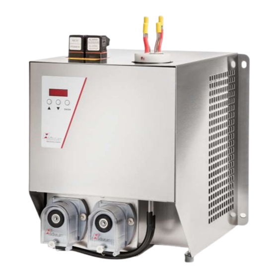
Sample gas cooler
EGK 1/2
Installation and Operation Instructions
Original instructions
BE450001
Bühler Technologies GmbH, Harkortstr. 29, D-40880 Ratingen
12/2022
Tel. +49 (0) 21 02 / 49 89-0, Fax: +49 (0) 21 02 / 49 89-20
E-Mail: analyse@buehler-technologies.com
Internet: www.buehler-technologies.com
Advertisement
Table of Contents

Related Manuals for Bühler technologies EGK 1


Summary of Contents for Bühler technologies EGK 1
- Page 1 Gas Analysis Sample gas cooler EGK 1/2 Installation and Operation Instructions Original instructions BE450001 Bühler Technologies GmbH, Harkortstr. 29, D-40880 Ratingen 12/2022 Tel. +49 (0) 21 02 / 49 89-0, Fax: +49 (0) 21 02 / 49 89-20 E-Mail: analyse@buehler-technologies.com...
- Page 2 Bühler Technologies GmbH, Harkortstr. 29, D-40880 Ratingen Tel. +49 (0) 21 02 / 49 89-0, Fax: +49 (0) 21 02 / 49 89-20 Internet: www.buehler-technologies.com E-Mail: analyse@buehler-technologies.com Read this instruction carefully prior to installation and/or use. Pay at- tention particularly to all advises and safety instructions to prevent in- juries.
-
Page 3: Table Of Contents
EGK 1/2 Contents Introduction ............................................. 2 Intended Use......................................... 2 Types............................................ 2 Scope of delivery ........................................ 2 Ordering instructions...................................... 2 Safety instructions ......................................... 3 Important advice ......................................... 3 General hazard warnings .................................... 4 Transport and storage ........................................ 5 4 Installation and connection ...................................... 6 Installation site requirements.................................. 6... -
Page 4: Introduction
EGK 1/2 1 Introduction 1.1 Intended Use This unit is intended for industrial use in gas analysis systems. It's an essential component for conditioning the sample gas to protect the analysis instrument from residual moisture in the sample gas. Please note the specifications in the data sheets on the specific intended use, existing material combinations, as well as pres- sure- and temperature limits. -
Page 5: Safety Instructions
EGK 1/2 2 Safety instructions 2.1 Important advice Operation of the device is only permitted if: – the product is used under the conditions described in the installation- and operation instruction, the intended application according to the type plate and the intended use. In case of unauthorized modifications done by the user Bühler Technolo- gies GmbH can not be held responsible for any damage, –... -
Page 6: General Hazard Warnings
EGK 1/2 2.2 General hazard warnings The equipment must be installed by a professional familiar with the safety requirements and risks. Be sure to observe the safety regulations and generally applicable rules of technology relevant for the installation site. Prevent malfunctions and avoid personal injuries and property damage. -
Page 7: Transport And Storage
EGK 1/2 3 Transport and storage Only transport the product inside the original packaging or a suitable alternative. The equipment must be protected from moisture and heat when not in use. It must be stored in a covered, dry and dust-free room at a temperature of -20 °C to 60 °C (-4 °F to 140 °F). -
Page 8: Installation And Connection
EGK 1/2 4 Installation and connection 4.1 Installation site requirements The unit is intended for wall-mounted or table-top use in enclosed areas. Adequate protection from the weather must be provided when used outdoors. Install the unit leaving enough room below the cooler to discharge the condensate. Leave room above for the gas supply. -
Page 9: Connecting The Heat Exchanger
EGK 1/2 4.2.2 Connecting the heat exchanger The gas inputs are marked in red. On glass heat exchangers the correct position of the seal is important when connecting the gas lines (see image). The seal con- sists of a silicone ring with a PTFE sleeve. The PTFE side must face the glass thread. - Page 10 EGK 1/2 Plug connection This device has one EN 175301-803 plug each for the power supply and the signal output. If the lead is connected correctly, these cannot be confused. Therefore please be sure to correctly reassemble the plugs after connecting the wires. Below you will find the pin assignments, with the numbers corresponding to those on the plugs: The supply line cross-sections must be suitable for the rated current.
-
Page 11: Operation And Control
EGK 1/2 5 Operation and control NOTICE The device must not be operated beyond its specifications. After switching on the cooler the block temperature will be displayed. The display will flash until the block temperature has reached the preset target value (± adjustable alarm range). The status contact is in the Alarm position. -
Page 12: Overview Of The Menu Items
EGK 1/2 5.1.1 Overview of the menu items Display of current temperature and operating state ____ Displayed is the block temperature with a resolution of 0,5°C/0.75 °F. By pressing the Enter button brings the Display ____ Current temperature display to the Main Menu. The unit of temperature is adjustable in the menu Global Settings (Celsius or Fahrenheit). -
Page 13: Description Of Menu Functions
EGK 1/2 5.2 Description of menu functions 5.2.1 Main menu Cooler From here you will be able to access to all relevant cooler settings. The related submenu allows you to select the target temperature and alarm thresholds. Globale settings (ToP Settings) Selection of the global temperature unit, either degree Celsius (C) or degree Fahrenheit (F). -
Page 14: Maintenance
EGK 1/2 6 Maintenance The basic version of the cooler requires no special maintenance. However, it may have different options depending on the cooler model. In this case the following maintenance must be per- formed regularly: – Optional peristaltic pump: Check hoses During maintenance, remember: –... -
Page 15: Service And Repair
EGK 1/2 7 Service and repair This chapter contains information on troubleshooting and correction should an error occur during operation. Repairs to the unit must be performed by Bühler authorised personnel. Please contact our Service Department with any questions: Tel.: +49-(0)2102-498955 or your agent For further information about our services and customised maintenance visit http://www.buehler-technologies.com/service. -
Page 16: Safety Instructions
EGK 1/2 Error Messages in the Display The display alternates between the temperature and error message, Problem / Malfunction Possible cause Action Error 01 – Interruption – Temperature sensor failure: Send in cooler Error 02 – Short circuit – Temperature sensor failure: Send in cooler 7.2 Safety instructions... -
Page 17: Cleaning And Removal Of The Heat Exchanger
EGK 1/2 7.3 Cleaning and removal of the heat exchanger Heat exchangers only need to be replaced or maintained if clogged or damaged. If they are clogged, we recommend checking if using a filter will avoid future occurrences. – Close gas supply. -
Page 18: Replacing The Hoses Of The Peristaltic Pump (Option)
EGK 1/2 7.5 Replacing the hoses of the peristaltic pump (option) – Turn off gas supply. – Switch the device off and disconnect power supply. – Remove the supplying and draining hoses from the pump (Take care of the safety instructions!). -
Page 19: Disposal
EGK 1/2 8 Disposal The refrigerant circuit of the cooler contains R134a refrigerant. The heat exchanger is charged with glycol-based coolant. The applicable national laws must be observed when disposing of the products. Disposal must not result in a danger to health and environment. -
Page 20: Appendices
EGK 1/2 9 Appendices 9.1 Gas cooler technical data Gas Cooler Technical Data Ready for operation after max. 15 minutes Rated cooling capacity (at 25 °C) 320 kJ/h Ambient temperature 5 °C to 50 °C Gas outlet dew point, preset approx. -
Page 21: Performance Data
EGK 1/2 9.3 Performance data Ambient temperature (°C) Remark: The limit curves for the heat exchangers exchanger apply to a dew point of 65 °C. 9.4 Diagram typical installation Sample gas/calibrating gas Sample gas 1 Sample gas probe 2 Sample gas line... -
Page 22: Heat Exchanger
EGK 1/2 9.5 Heat exchanger 9.5.1 Heat exchanger description The energy content of the sample gas and the required cooling capacity of the gas cooler is determined by three parameters: gas temperature ϑ , (inlet) dew point τ (moisture content) and volume flow v. The outlet dew point rises with increasing energy content of the gas. -
Page 23: Dimensions (Mm)
EGK 1/2 9.6 Dimensions (mm) BE450001 ◦ 12/2022 Bühler Technologies GmbH... -
Page 24: Attached Documents
EGK 1/2 10 Attached documents – Declaration of conformity KX450001 – RMA - Decontamination Statement Bühler Technologies GmbH BE450001 ◦ 12/2022... - Page 27 RMA-Formular und Erklärung über Dekontaminierung RMA-Form and explanation for decontamination RMA-Nr./ RMA-No. Die RMA-Nr. bekommen Sie von Ihrem Ansprechpartner im Vertrieb oder Service. Bei Rücksendung eines Altgeräts zur Entsorgung tragen Sie bitte in das Feld der RMA-Nr. "WEEE" ein./ You may obtain the RMA number from your sales or ser- vice representative.
- Page 28 Dekontaminierungserklärung DE000011 Bühler Technologies GmbH, Harkortstr. 29, D-40880 Ratingen 12/2022 Tel. +49 (0) 21 02 / 49 89-0, Fax: +49 (0) 21 02 / 49 89-20 E-Mail: service@buehler-technologies.com Internet: www.buehler-technologies.com...
Need help?
Do you have a question about the EGK 1 and is the answer not in the manual?
Questions and answers