Table of Contents
Advertisement
Quick Links
Fluidcontrol
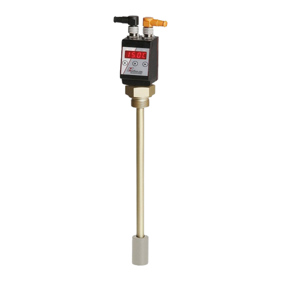
Level- and temperature sensor
Nivotemp NT M-XP
Installation and Operation Instructions
Original instructions
BE100023
Bühler Technologies GmbH, Harkortstr. 29, D-40880 Ratingen
06/2021
Tel. +49 (0) 21 02 / 49 89-0, Fax: +49 (0) 21 02 / 49 89-20
E-Mail: fluidcontrol@buehler-technologies.com
Internet: www.buehler-technologies.com
Advertisement
Table of Contents

Related Manuals for Bühler technologies Nivotemp NT M-XP


Summary of Contents for Bühler technologies Nivotemp NT M-XP
- Page 1 Fluidcontrol Level- and temperature sensor Nivotemp NT M-XP Installation and Operation Instructions Original instructions BE100023 Bühler Technologies GmbH, Harkortstr. 29, D-40880 Ratingen 06/2021 Tel. +49 (0) 21 02 / 49 89-0, Fax: +49 (0) 21 02 / 49 89-20 E-Mail: fluidcontrol@buehler-technologies.com...
- Page 2 Bühler Technologies GmbH, Harkortstr. 29, D-40880 Ratingen Tel. +49 (0) 21 02 / 49 89-0, Fax: +49 (0) 21 02 / 49 89-20 Internet: www.buehler-technologies.com E-Mail: fluidcontrol@buehler-technologies.com Read this instruction carefully prior to installation and/or use. Pay at- tention particularly to all advises and safety instructions to prevent in- juries.
-
Page 3: Table Of Contents
Nivotemp NT M-XP Contents Introduction............................................. 3 Intended Use......................................... 3 Functionality......................................... 3 1.2.1 Liquid level monitoring .................................. 3 1.2.2 Temperature monitor .................................. 3 Design types.......................................... 3 Model key.......................................... 4 Scope of Delivery........................................ 4 Safety instructions......................................... 5 Important advice ......................................... 5 General hazard warnings .................................... 6 Transport and storage ........................................ 7 4 Setup and connection ........................................ - Page 4 Nivotemp NT M-XP Troubleshooting ........................................ 28 Spare parts and accessories ................................... 29 8 Disposal ............................................ 30 9 Appendices............................................ 31 Technical Data NT M-XP .................................... 31 Dimensions NT M-XP...................................... 32 Standard pin assignment NT M-XP................................ 33 Current settings......................................... 34 Display ranges ........................................ 34 Display resolution ...................................... 35 Menu Sequence Overview .................................... 36 10 Attached documents ........................................
-
Page 5: Introduction
Nivotemp NT M-XP 1 Introduction 1.1 Intended Use Level switches are used to monitor the liquid level and temperature in fluid systems. Level switches must not be used in highly flammable or corrosive liquids. The medium must not contain particles, particularly metallic particles, to prevent deposits on the float or between the float and switching tube. -
Page 6: Model Key
Nivotemp NT M-XP 1.4 Model key - - - - - - - - - - - - - - - - NT M-XP Option Type designation with display, control unit Oval flange adapter to G1" Version Output card Brass... -
Page 7: Safety Instructions
Nivotemp NT M-XP 2 Safety instructions 2.1 Important advice Operation of the device is only valid if: – the product is used under the conditions described in the installation- and operation instruction, the intended application according to the type plate and the intended use. In case of unauthorized modifications done by the user Bühler Technolo- gies GmbH can not be held responsible for any damage, –... -
Page 8: General Hazard Warnings
Nivotemp NT M-XP 2.2 General hazard warnings The equipment must be installed by a professional familiar with the safety requirements and risks. Be sure to observe the safety regulations and generally applicable rules of technology relevant for the installation site. Prevent malfunctions and avoid personal injuries and property damage. -
Page 9: Transport And Storage
Nivotemp NT M-XP 3 Transport and storage Only transport the product inside the original packaging or a suitable alternative. The equipment must be protected from moisture and heat when not in use. It must be stored in a covered, dry, dust-free room at room temperature. -
Page 10: Setup And Connection
Nivotemp NT M-XP 4 Setup and connection DANGER Electric voltage Risk of electric shock a) Always disconnect the unit from the mains before performing work. b) Secure the equipment from accidental restarting. c) The equipment may only be installed, maintained and put into operation by instruc- ted, competent personnel. -
Page 11: Operation And Control
Nivotemp NT M-XP 5 Operation and control NOTICE The device must not be operated beyond its specifications. 5.1 Start-up procedure The device will automatically switch on when connected to power. It will first briefly display the software version, at which time the device will also check the built-in components. -
Page 12: General Key Functions
Nivotemp NT M-XP 5.3 General key functions The keys below the display are used for operation. The menu controls are detailed in the following chapters. Mode Function – Measurement display: Change measured variables displayed. – In the menu: Move down one menu level. -
Page 13: Menu Overview
Nivotemp NT M-XP 5.5 Menu overview The menu structure is based on the VDMA standard sheet 24574-1. The menu structure is hierarchic. The top menu level contains the main menu items, e.g. oil, tEMP, F, diA, E. Each main menu contains additional submenu items. -
Page 14: Changing Basic Settings
Nivotemp NT M-XP The basic device settings can be changed. General settings can be configured under Basic Settings Advanced Functions (b. E These settings should be configured first, as they affect the displays and settings for the individual menus. These settings are e.g. -
Page 15: Define Switching Outputs
Nivotemp NT M-XP 5.6.3 Define switching outputs Here you can define the switching outputs. Use the “Define switching outputs” function to define the switching outputs (r. o u1 r. o u2). The switching outputs can be configured as Err, tEMP... -
Page 16: Reallocate Switching Outputs
Nivotemp NT M-XP 5.6.5 Reallocate switching outputs This describes how to change the allocation of switching outputs for switching output 1. This procedure also applies to all other switching outputs. b. E F reassign OX r. o u_ ____ Basic EF Selection menu Basic Adv. -
Page 17: Enable/Disable Keylock
Nivotemp NT M-XP 5.6.7 Enable/disable keylock The keylock can be enabled to prevent unauthorised changes to the device settings. Lock Selection menu Basic EF b. E F Lock Device Locks the keys Basic Adv. Functions 0 - 999 The keylock will be enabled after entering at least one digit > 0. A dot indicates the active digit during this input. -
Page 18: Assigning The Upper Limit Of The Sensor Measuring Range
Nivotemp NT M-XP 5.6.9 Assigning the upper limit of the sensor measuring range This determines the display value (upper limit for the measuring range) for the maximum liquid level: Set Upper o. H i Selection menu ____ Basic EF b. E F Basic Adv. - Page 19 Nivotemp NT M-XP Version with 2 switching outputs: Switching outputs Basic Settings 5% / 2% o. u ni t. u ni °C 55°C o. H i o. L o r. o u1 r. o u2 tEMP FASt Version with 4 switching outputs:...
-
Page 20: Switching Outputs
Nivotemp NT M-XP 5.7 Switching outputs All switching outputs are configured the same way. The switching output number is therefore represented by x. Open the switching output to be configured from the menu for the respective measured variable. ____ Display... -
Page 21: Switching Output X: Upper Switching Limit (Switching Point)
Nivotemp NT M-XP Example: F ILo = 15 °C, F IHi = 80 °C Frequency output If the output is defined as a frequency output, a with temperature T and frequency f: square wave signal with a frequency between 1 Hz and 100 Hz proportional to the measurement will be... -
Page 22: Switching Output X: Lower Switching Limit (Switch-Back Point)
Nivotemp NT M-XP 5.7.3 Switching output x: Lower switching limit (switch-back point) The lower switching limit for switching output Out x can be defined with the following submenu: ____ Out X out_ ____ Selection menu ____ Measured variable rPI FLI F I. L o [ o. -
Page 23: Switching Output X: Testing The Switching Output
Nivotemp NT M-XP 5.7.6 Switching output x: Testing the switching output The switching output test can be started with the following menu: ____ Out X Check Out X Measured variable out_ EF X C. o u_ Selection menu ____ Settings menu OUTX... -
Page 24: Analogue Outputs
Nivotemp NT M-XP Factory setting Status function State Status LED 3 inverted Temperature rises to > 70 °C PNP switching output 3 closed LED3 ON LED3 OFF Temperature rises to > 80 °C Error PNP switching output 4 closed LED4 and LED3 ON only LED4 ON Temperature falls to <... -
Page 25: Analogue Output X: Lower Limit Assignment
Nivotemp NT M-XP Temperature Used to configure at which temperature to output the maximum analogue signal. This is configured in menu: ____ Measured variable Analog OutX Analog MaxX A I. H i Selection menu ____ Settings menu Analog X [ o. L o - o. H i ]... -
Page 26: Analogue Output X: Testing The Analogue Output
Nivotemp NT M-XP 5.8.4 Analogue output x: Testing the analogue output The analogue output can be tested. The highest, mean and lowest analogue value can be output successively. This is configured in menu: ____ Analog OutX Check AnX C. A n_... -
Page 27: Maximum And Minimum Liquid Level
Nivotemp NT M-XP The information displayed will alternate between the index and time for entry x, e.g. Jor1 ⇔ 1. 4 h for the most recent event 1.4 hours ago. Press the key to return to the submenu or use to select the next journal entry. -
Page 28: Define Switching Output To Log
Nivotemp NT M-XP 5.9.4 Define switching output to log Used to select the switching output to be logged. Only one switching output can be logged. Diagnostic SJ. o u Selection menu out_ Set Journal Out Out I - Out_ Diagnostics menu Output monitoring Switching output logging. -
Page 29: Cleaning And Maintenance
Nivotemp NT M-XP 6 Cleaning and Maintenance This device is maintenance-free. The method for cleaning the devices must be adapted to the IP protection class of the devices. Do not use cleaners which could damage the device materials. BE100023 ◦ 06/2021... -
Page 30: Service And Repair
Nivotemp NT M-XP 7 Service and repair This chapter contains information on troubleshooting and correction should an error occur during operation. Repairs to the unit must be performed by Bühler authorised personnel. Please contact our Service Department with any questions: Tel.: +49-(0)2102-498955 or your agent... -
Page 31: Spare Parts And Accessories
Nivotemp NT M-XP Possible errors Problem / Malfunction Possible cause Action Switching output not trigger- – Switching output configured incorrectly – In submenu Coux: “Test Switching Output“ to ing when exceeding limits ensure normal mode – Switching output defect – In submenu Coux: “Test Switching Output” to... -
Page 32: Disposal
Nivotemp NT M-XP 8 Disposal Dispose of parts so as not to endanger the health or environment. Follow the laws in the country of use for disposing of elec- tronic components and devices during disposal. 30 Bühler Technologies GmbH BE100023 ◦ 06/2021... -
Page 33: Appendices
Nivotemp NT M-XP 9 Appendices 9.1 Technical Data NT M-XP Basic unit Version Operating pressure max. 1 bar Operating temperature -20 °C to +80 °C Float SK 171 Min. fluid density 0.80 kg/dm³ Lengths (all versions) 200, 280, 370, 500, 650, 820 mm (other lengths available upon request) Min. -
Page 34: Dimensions Nt M-Xp
Nivotemp NT M-XP 2S-KN-KT 4S-KN-KT 6S-KN-KT Plug (base) 2 x M12 – 4-pin 1 x M12 – 8-pin 2 x M12 – 4-pin / 8-pin Switching outputs 2 x freely programmable 4 x freely programmable 6 x freely programmable with arbitrary assignment... -
Page 35: Standard Pin Assignment Nt M-Xp
Nivotemp NT M-XP 9.3 Standard pin assignment NT M-XP Version 1D1S Plug 1x M12 4-pin 2x M12 4-pin 1x M12 8-pin Connection Plug A Plug B schematic +24 V DC +24 V DC +24 V DC +24 V DC +24 V DC... -
Page 36: Current Settings
Nivotemp NT M-XP 9.4 Current settings Switching outputs Basic Settings Diagnostics o. u ni SJ. o u t. u ni do. M M o. H i dt. M M o. L o r. o u1 r. o u2 r. o u3 r. -
Page 37: Display Resolution
Nivotemp NT M-XP 9.6 Display resolution Range x = |Max - Min| °C, °F, percent, cm, inch, litre, gallon, none (non1) (up to 1 decimal place) (1 fixed-point number) cm, inch, litre, gallon Range x Resolution Range x Resolution x < 50 x <... -
Page 38: Menu Sequence Overview
Nivotemp NT M-XP 9.7 Menu Sequence Overview Main menu Submenu 1 Submenu 2 Submenu 3 Settings and Display Menu o__i Configuration Shortcut Equipment configuration or 60s no action: Exit main/submenu ____ Display ____ Switch ____ ____ Switches the measurement display level / temperature... -
Page 39: Attached Documents
Nivotemp NT M-XP 10 Attached documents – Declaration of conformity: KX100020 – RMA - Decontamination Statement BE100023 ◦ 06/2021 Bühler Technologies GmbH... - Page 41 RMA-Formular und Erklärung über Dekontaminierung RMA-Form and explanation for decontamination RMA-Nr./ RMA-No. Die RMA-Nummer bekommen Sie von Ihrem Ansprechpartner im Vertrieb oder Service./ You may obtain the RMA number from your sales or service representative. Zu diesem Rücksendeschein gehört eine Dekontaminierungserklärung. Die gesetzlichen Vorschriften schreiben vor, dass Sie uns diese Dekontaminierungserklärung ausgefüllt und unterschrieben zurücksenden müssen.
- Page 42 Dekontaminierungserklärung DE000011 Bühler Technologies GmbH, Harkortstr. 29, D-40880 Ratingen 01/2019 Tel. +49 (0) 21 02 / 49 89-0, Fax: +49 (0) 21 02 / 49 89-20 E-Mail: service@buehler-technologies.com Internet: www.buehler-technologies.com...
Need help?
Do you have a question about the Nivotemp NT M-XP and is the answer not in the manual?
Questions and answers