Synway SMG Series User Manual
Digital gateway
Hide thumbs
Also See for SMG Series:
- User manual (141 pages) ,
- User manual (100 pages) ,
- User manual (98 pages)

Related Manuals for Synway SMG Series


Summary of Contents for Synway SMG Series
- Page 1 Synway SMG Series Digital Gateway SMG2030 SMG2030S SMG2060 SMG2060S SMG2120 SMG2120S SMG3008 SMG3016 Digital Gateway Version 1.6.5 Synway Information Engineering Co., Ltd www.synway.net...
-
Page 2: Table Of Contents
PCM Trunk Group ....................59 3.4.7 Number-receiving Rule ...................61 3.4.8 Reception Timeout....................64 3.4.9 PSTN Forwarding ....................65 SS7 Settings ....................67 3.5.1 SS7.........................68 3.5.2 TUP ........................69 3.5.3 TUP Number Parameter ..................71 3.5.4 ISUP ........................73 SMG Series Digital Gateway User Manual (Version 1.6.5) Page i... - Page 3 3.12.20 Device Lock ......................146 3.12.21 Restart ........................147 Chapter 4 Typical Applications .............148 Application 1 ....................148 4.1.1 Configurations for Headquarters................149 4.1.2 Configurations for Branch A..................153 4.1.3 Configurations for Branch B..................157 SMG Series Digital Gateway User Manual (Version 1.6.5) Page ii...
- Page 4 Appendix C ISUP (ISDN) Pending Cause to SIP Status Code ..168 Appendix D TUP Pending Cause to SIP Status Code .....170 Appendix E Direction for CDR Use...........171 Appendix F Technical/sales Support ..........172 SMG Series Digital Gateway User Manual (Version 1.6.5) Page iii...
-
Page 5: Copyright Declaration
Synway has made every effort to ensure the accuracy of this document but does not guarantee the absence of errors. Moreover, Synway assumes no responsibility in obtaining permission and authorization of any third party patent, copyright or product involved in relation to the use of this document. -
Page 6: Revision History
New revision Version 1.6.3 2016-01 New revision Version 1.6.4 2016-09 New revision Version 1.6.5 2017-06 New revision Note: Please visit our website http://www.synway.net to obtain the latest version of this document. SMG Series Digital Gateway User Manual (Version 1.6.5) Page v... -
Page 7: Chapter 1 Product Introduction
Chapter 1 Product Introduction Thank you for choosing Synway SMG Series Digital Gateway! The Synway SMG series digital gateway products (hereinafter referred to as ‘SMG digital gateway’) are mainly used for connecting PSTN or enterprise PBX with the IP telephony network or IP PBX. -
Page 8: Feature List
Maintain & Upgrade Description Support of configurations through the WEB user interface WEB Configuration Chinese, English Language Support of user interface, gateway service, kernel and firmware upgrades based Software Upgrade on WEB SMG Series Digital Gateway User Manual (Version 1.6.5) Page 2... -
Page 9: Hardware Description
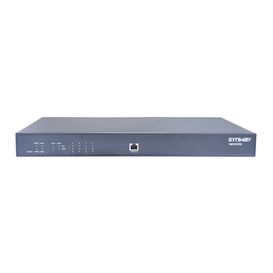
Stud E1/T1 Power1 Key Interface Power2 Key Figure 1-3 Rear View Screw Holes for Ventilation Foot Bracket Holes Figure 1-4 Left View (b) See below figures for SMG3000 series appearance: SMG Series Digital Gateway User Manual (Version 1.6.5) Page 3... - Page 10 Power on/off the SMG digital gateway. You can turn on the two power keys at the Power Key same time to have the power supply working in the hot-backup mode. Restore the gateway to factory settings. Reset Button Description SMG Series Digital Gateway User Manual (Version 1.6.5) Page 4...
-
Page 11: Alarm Info
During runtime, if the alarm indicator lights up or flashes, it indicates that the device goes abnormal. If you cannot figure out and solve the problem by yourself, please contact our to find the contact way. technicians for help. Go to Appendix F Technical/sales Support SMG Series Digital Gateway User Manual (Version 1.6.5) Page 5... -
Page 12: Chapter 2 Quick Guide
The synchronization indicator starts working only after the device is powered on and successfully initialized. TTip Transmit TRing Receive RTip RRing SMG Series Digital Gateway User Manual (Version 1.6.5) Page 6... - Page 13 DPC. Fill in ‘SP Code’ with the signaling point code of the remote end (i.e. signaling destination), select the linkset configured in Step 3 for ‘Linkset’ and use the default values for the other configuration items. After modification, click ‘Save’. SMG Series Digital Gateway User Manual (Version 1.6.5) Page 7...
- Page 14 Note: After configuring the ISDN interface, you shall restart the service to validate the settings. Refer to 3.12.21 Restart for detailed instructions. SS1: The configuration interface related to SS1 is SS1. On your initial use of the SMG digital gateway, SMG Series Digital Gateway User Manual (Version 1.6.5) Page 8...
- Page 15 5060. Provided 123 is a number which conforms to the number receiving rule of the remote device. Initiate a call from SIP terminal 0 to the IP address 192.168.0.101 (in the format: 123@192.168.0.101) and you can establish a call conversation via PCM[1] to SMG Series Digital Gateway User Manual (Version 1.6.5) Page 9...
- Page 16 During runtime, if the alarm indicator lights up or flashes, it indicates that the device goes abnormal. If you cannot figure out and solve the problem by yourself, please contact our SMG Series Digital Gateway User Manual (Version 1.6.5) Page 10...
- Page 17 Synway Information Engineering Co., Ltd technicians for help. Otherwise it may lead to a drop in performance or unexpected errors. SMG Series Digital Gateway User Manual (Version 1.6.5) Page 11...
-
Page 18: Chapter 3 Web Configuration
‘System Tools Change Password’ on the WEB interface. For detailed instructions, refer to 3.12.19 Change Password. After login, you can see the main interface as below. SMG Series Digital Gateway User Manual (Version 1.6.5) Page 12... - Page 19 Synway Information Engineering Co., Ltd Figure 3-2 Main Interface SMG Series Digital Gateway User Manual (Version 1.6.5) Page 13...
-
Page 20: Operation Info
Operation Info includes seven parts: System Info, PSTN Status, PCM Info, SS7 Serve, Call Monitor, Call Count and Warning Info showing the current running status of the gateway. See Figure 3-3. Figure 3-3 Operation Info SMG Series Digital Gateway User Manual (Version 1.6.5) Page 14... -
Page 21: System Info
MAC address of LAN 1 or LAN 2. MAC Address The three parameters from left to right are IP address, subnet mask and default IP Address gateway of LAN 1 or LAN 2. SMG Series Digital Gateway User Manual (Version 1.6.5) Page 15... - Page 22 Current version of the gateway service. Gateway Current version of Uboot. Uboot Current version of the system kernel on the gateway. Kernel Current version of the firmware on the gateway. Firmware SMG Series Digital Gateway User Manual (Version 1.6.5) Page 16...
-
Page 23: Pstn Status
Synway Information Engineering Co., Ltd 3.2.2 PSTN Status Figure 3-5 PSTN Status Interface for E1 Lines SMG Series Digital Gateway User Manual (Version 1.6.5) Page 17... - Page 24 For Time Slot 0, the channel state indicates the synchronization status of State E1/T1. State Color Description Frame synchronization normal. The synchronization Frame Sync status is 0x0. SMG Series Digital Gateway User Manual (Version 1.6.5) Page 18...
- Page 25 E1/T1 is not used. For the other channels, the channel states include: State Icon Description Unusable The channel is unavailable. Circuit Reset The circuit is being reset. Idle The channel is available. SMG Series Digital Gateway User Manual (Version 1.6.5) Page 19...
- Page 26 Search button, the gateway does a fuzzy search and locates that the ongoing call whose CalledID contains the character 111 occurs on Time Slot No. 8 of PCM 0. SMG Series Digital Gateway User Manual (Version 1.6.5) Page 20...
- Page 27 Note: Click Record to start recording on the matched channel. If more than one channel match a condition, only the channel with the largest number among them will be recorded. SMG Series Digital Gateway User Manual (Version 1.6.5) Page 21...
-
Page 28: Pcm Info
Users can see the SS7 Server option in the menu only when the configuration item Signaling Protocol on the PCM settings interface is set to SS7-TUP or SS7-ISUP. The SMG2030S, SMG2060S and SMG2120S series don’t support SS7. SMG Series Digital Gateway User Manual (Version 1.6.5) Page 22... - Page 29 If this item is ticked, the receive/transmit message list will display the SNT Display SNT messages. Messages If this item is ticked, the receive/transmit message list will display the SNM Display SNM messages. Messages SMG Series Digital Gateway User Manual (Version 1.6.5) Page 23...
- Page 30 Status Bar 4: Client information This region displays the information about client IP address and connection state. The table below explains the information items in Status Bar 4. Item Description Client number. Client SMG Series Digital Gateway User Manual (Version 1.6.5) Page 24...
- Page 31 2: FIBR illegal positioning processor failure both ends positioned/ 3: T2 timeout processor ready failure 4: T6 timeout, the positioned/ remote end busy not ready SMG Series Digital Gateway User Manual (Version 1.6.5) Page 25...
-
Page 32: Call Monitor
Runtime log records all MTP3 commands and error information that pops up during the operation. This status bar displays all the log records generated after the digital gateway starts. 3.2.5 Call Monitor SMG Series Digital Gateway User Manual (Version 1.6.5) Page 26... - Page 33 Note: If a channel has been monitored from the very beginning, the monitoring, even if not yet cancelled, will terminate once the channel is removed from the monitor list. SMG Series Digital Gateway User Manual (Version 1.6.5) Page 27...
-
Page 34: Call Count
The percentage of answered calls to total calls by all methods. The call methods Answering Rate include SIP Incoming Call, SIP Outgoing Call, IP PSTN call and PSTN IP call. The average call length for all connected calls. Average Call Length SMG Series Digital Gateway User Manual (Version 1.6.5) Page 28... - Page 35 Total number of the calls which fail due to other unknown reasons. Others The percentage of the calls with a release cause to total calls. Percentage SMG Series Digital Gateway User Manual (Version 1.6.5) Page 29...
-
Page 36: Warning Info
SIP; SIP Account is used for registering SIP accounts to the SIP server; SIP Trunk Group is to manage SIP trunks by group; and Media is to set the RTP port and the payload type. Figure 3-13 SIP Settings SMG Series Digital Gateway User Manual (Version 1.6.5) Page 30... -
Page 37: Sip Settings
Synway Information Engineering Co., Ltd 3.3.1 SIP Settings SMG Series Digital Gateway User Manual (Version 1.6.5) Page 31... - Page 38 Synway Information Engineering Co., Ltd SMG Series Digital Gateway User Manual (Version 1.6.5) Page 32...
- Page 39 There are two optional ways to obtain the calling party number: from Username of “From” Field or from Displayname of “From” Field. The default value is from Obtain CallerID from Username of “From” Field. SMG Series Digital Gateway User Manual (Version 1.6.5) Page 33...
- Page 40 UDP header during RTP transmission. When this feature is enabled, a corresponding Rport field will be added to the Rport Via message of SIP. By default, it is disabled. SMG Series Digital Gateway User Manual (Version 1.6.5) Page 34...
- Page 41 If the call is not answered within the Maximum Wait Answer specified time period, it will be canceled by the channel automatically. The Time default value is 60, calculated by s. SMG Series Digital Gateway User Manual (Version 1.6.5) Page 35...
-
Page 42: Sip Trunk
See Figure 3-15 for the SIP trunk settings interface. A new SIP trunk can be added by the Add New button on the bottom right corner of the list in the above figure. See Figure 3-16 for the SIP trunk adding interface. SMG Series Digital Gateway User Manual (Version 1.6.5) Page 36... - Page 43 Maximum number of voice channels for the outgoing calls allocated by the SIP Outgoing Voice trunk to the gateway. Resource Maximum number of voice channels for the Incoming calls allocated by the SIP Incoming Voice trunk to the gateway. Resource SMG Series Digital Gateway User Manual (Version 1.6.5) Page 37...
- Page 44 Click Modify in Figure 3-15 to modify a SIP trunk. See Figure 3-17 for the SIP trunk modification interface. The configuration items on this interface are the same as those on the Add New SIP Trunk interface. SMG Series Digital Gateway User Manual (Version 1.6.5) Page 38...
-
Page 45: Sip Register
See Figure 3-18 for the SIP Register Configuration interface. By default, there is no SIP register available on the gateway. Click Add New to add them manually. See Figure 3-19. SMG Series Digital Gateway User Manual (Version 1.6.5) Page 39... - Page 46 Address of the SIP server to which the SIP trunk is registered. Register Address The signaling port of the SIP trunk. Register Port Domain name of the gateway used for SIP registry. Domain Name SMG Series Digital Gateway User Manual (Version 1.6.5) Page 40...
- Page 47 Click Modify in Figure 3-20 to modify a SIP register. The configuration items on the SIP Register Modification Interface are the same as those on the Add New SIP Register interface. SMG Series Digital Gateway User Manual (Version 1.6.5) Page 41...
-
Page 48: Sip Account
See Figure 3-22 for the SIP account settings interface. A new SIP account can be added by the Add New button on the bottom right corner of the list in the above figure. See Figure 3-23 for the SIP account adding interface. SMG Series Digital Gateway User Manual (Version 1.6.5) Page 42... - Page 49 Click Modify in Figure 3-22 to modify a SIP account. See Figure 3-24 for the SIP account modification interface. The configuration items on this interface are the same as those on the Add New SIP Account interface. SMG Series Digital Gateway User Manual (Version 1.6.5) Page 43...
-
Page 50: Sip Trunk Group
See Figure 3-25 for SIP trunk group settings interface. A new SIP trunk group can be added by the Add New button on the bottom right corner of the list in the above figure. See Figure 3-26 for the SIP trunk group adding interface. SMG Series Digital Gateway User Manual (Version 1.6.5) Page 44... - Page 51 SIP trunk has been occupied. The ticked SIP trunks herein will be SIP Trunks displayed in the column ‘SIP Trunks’ in Figure 3-25. After configuration, click Save to save the settings into the gateway or click Cancel to cancel the SMG Series Digital Gateway User Manual (Version 1.6.5) Page 45...
- Page 52 Uncheck All means to cancel all selections on the current page; Inverse means to uncheck the selected items and check the unselected. To clear all SIP trunk groups at a time, click the Clear All button in Figure 3-25. SMG Series Digital Gateway User Manual (Version 1.6.5) Page 46...
-
Page 53: Media Settings
Refer to 3.12.21 Restart for detailed instructions. The table below explains the items shown in Figure 3-28. SMG Series Digital Gateway User Manual (Version 1.6.5) Page 47... - Page 54 Sets the maximum delay can be increased during one silence period. Rnage of value: 0~280, calculated by ms, with the default value of 30, JitterIncreaseMax Note: Only when JitterMode is to Adaptive Mode will this item be shown. SMG Series Digital Gateway User Manual (Version 1.6.5) Page 48...
-
Page 55: Pcm Settings
10 / 20 / 40 / 60 3.4 PCM Settings PCM Settings includes nine parts: PSTN, E1 Outgoing Call Timer, Circuit Maintenance, PCM, PCM Trunk, PCM Trunk Group, Number-Receiving Rule, Reception Timeout and PSTN SMG Series Digital Gateway User Manual (Version 1.6.5) Page 49... - Page 56 Synway Information Engineering Co., Ltd Forwarding. See Figure 3-29. Figure 3-29 PCM Settings SMG Series Digital Gateway User Manual (Version 1.6.5) Page 50...
-
Page 57: Pstn
Synway Information Engineering Co., Ltd 3.4.1 PSTN Figure 3-30 PSTN Settings Interface See Figure 3-30 for the PSTN Settings interface. The table below explains the items shown in the above figure. SMG Series Digital Gateway User Manual (Version 1.6.5) Page 51... - Page 58 Outgoing CalleeID Range of value: 0~50. The default value is 0, not limited. SMG Series Digital Gateway User Manual (Version 1.6.5) Page 52...
-
Page 59: E1 Outgoing Call Timer
404 message directly once the call time for all E1 runs out. Note: This interface will be displayed only when the configuration item “ Time Limit for E1 Outgoing ” in PSTN setting is enabled. Calls per Month SMG Series Digital Gateway User Manual (Version 1.6.5) Page 53... -
Page 60: Circuit Maintenance
Check All means to select all available items for the current port; Uncheck All means to cancel all selections for the current port; Inverse means to uncheck the selected items and check the unselected. SMG Series Digital Gateway User Manual (Version 1.6.5) Page 54... -
Page 61: Pcm
PCM to process outgoing calls. This is valid only when the configuration item Start TS, Signaling Protocol is set to SS1. Amount Sets whether to enable the CRC-4 verification feature. By default, this feature is Enabled. CRC-4 SMG Series Digital Gateway User Manual (Version 1.6.5) Page 55... - Page 62 Check this item to apply the above settings (excluding Clock) to all PCMs. Apply to All PCMs After configuration, click Save to save the settings into the gateway or click Close to cancel the settings. SMG Series Digital Gateway User Manual (Version 1.6.5) Page 56...
-
Page 63: Pcm Trunk
See Figure 3-35 for the PCM Trunk Configuration interface. By default, there is no PCM trunk available on the gateway. Click Add New or Batch Add to add them manually. See Figure 3-36, Figure 3-37. Figure 3-36 Add PCM Trunk Interface SMG Series Digital Gateway User Manual (Version 1.6.5) Page 57... - Page 64 Click Modify in Figure 3-38 to modify a PCM trunk. The configuration items on the PCM Trunk Modification Interface are the same as those on the Add PCM Trunk interface. SMG Series Digital Gateway User Manual (Version 1.6.5) Page 58...
-
Page 65: Pcm Trunk Group
See Figure 3-40 for the PCM trunk group settings interface. A new PCM trunk group can be added by the Add New button on the bottom right corner of the list in the above figure. See Figure 3-41 for the PCM trunk group adding interface. SMG Series Digital Gateway User Manual (Version 1.6.5) Page 59... - Page 66 PCM trunk has been occupied. The ticked PCM trunks herein will be PCM Trunks displayed in the column ‘PCM Trunks’ in Figure 3-40. After configuration, click Save to save the settings into the gateway or click Close to cancel the settings. SMG Series Digital Gateway User Manual (Version 1.6.5) Page 60...
-
Page 67: Number-Receiving Rule
A new number-receiving rule can be added by the Add New button on the bottom right corner. See Figure 3-44 for the number-receiving rule adding interface. SMG Series Digital Gateway User Manual (Version 1.6.5) Page 61... - Page 68 The unique index of each number-receiving rule, which denotes its priority. A number-receiving rule with a smaller index value has a higher priority and will be Index checked earlier while matching. SMG Series Digital Gateway User Manual (Version 1.6.5) Page 62...
- Page 69 15 or 18 Any 8-digit number starting with 2, 3, 5, 6 [2-3,5-7]xxxxxxx or 7 Any 8-digit number starting with 81, 82, 8[1-9]xxxxxx 83, 84, 85, 86, 87, 88 or 89 SMG Series Digital Gateway User Manual (Version 1.6.5) Page 63...
-
Page 70: Reception Timeout
Clear All button in Figure 3-43. 3.4.8 Reception Timeout Figure 3-46 Number-receiving Timeout Info Interface See Figure 3-46 for the number-receiving timeout info interface. The table below explains the items shown in the above figure. SMG Series Digital Gateway User Manual (Version 1.6.5) Page 64... -
Page 71: Pstn Forwarding
It is used to set the corresponding number for the call from PSTN to IP which fails and is forwarded back to PSTN. Click Add New to add them manually. SMG Series Digital Gateway User Manual (Version 1.6.5) Page 65... - Page 72 The configuration items on this interface are the same as those on the Add PSTN Forwarding Number Table interface. Note that the item No. cannot be modified. SMG Series Digital Gateway User Manual (Version 1.6.5) Page 66...
-
Page 73: Ss7 Settings
SMG2120S series don’t support SS7.). SS7 Settings includes eight parts: SS7, TUP, TUP Number Param, ISUP, Number Param, Original CalleeID Pool, Redirecting Number Pool (Hidden item) and SS7 Server. See Figure 3-52. Figure 3-52 SS7 Settings SMG Series Digital Gateway User Manual (Version 1.6.5) Page 67... -
Page 74: Ss7
If this feature is enabled, two SS7 servers are used at the same time in the system. The configuration items Master IP and Slave IP are respectively used to set the IP Dual Gateway addresses of the master and slave servers. SMG Series Digital Gateway User Manual (Version 1.6.5) Page 68... -
Page 75: Tup
If this configuration item is enabled, the called party number string sent by the Send ST Signal with gateway contains the ST signal in the outgoing call. By default this item is CalleeID in Outgoing Call disabled. SMG Series Digital Gateway User Manual (Version 1.6.5) Page 69... - Page 76 CalleeID of an Incoming is, the local end has received all the n digits of the called party number of the Call incoming call, the number reception will be regarded as finished. SMG Series Digital Gateway User Manual (Version 1.6.5) Page 70...
-
Page 77: Tup Number Parameter
Prefix before Number the CallerID/CalleeID which has been manipulated. Manipulation The corresponding number for a calling party number parameter, which starts from 0. SMG Series Digital Gateway User Manual (Version 1.6.5) Page 71... - Page 78 Clear All button in Figure 3-55. Note: If there are two or more calling party numbers with the same prefix, the one numbered the smallest is valid and all the others become invalid. SMG Series Digital Gateway User Manual (Version 1.6.5) Page 72...
-
Page 79: Isup
Synway Information Engineering Co., Ltd 3.5.4 ISUP SMG Series Digital Gateway User Manual (Version 1.6.5) Page 73... - Page 80 Synway Information Engineering Co., Ltd SMG Series Digital Gateway User Manual (Version 1.6.5) Page 74...
- Page 81 Sets the generic number parameter in IAM message, with the default value of Send Generic Number disabled. Sets the generic number for the IAM message, it is valid only when the feature of Generic Number Send Generic Number is enabled. Property SMG Series Digital Gateway User Manual (Version 1.6.5) Page 75...
- Page 82 If the call is not answered within the specified time period, it will be canceled Time (s) by the channel automatically. The default value is 180, calculated by s. SMG Series Digital Gateway User Manual (Version 1.6.5) Page 76...
- Page 83 Sets whether the IAM message contains the optional forward call indicator. By Optional Forward Call default this feature is disabled. If this feature is enabled, its value is usually Indicator determined by the remote PBX, with the default value of 0x00. SMG Series Digital Gateway User Manual (Version 1.6.5) Page 77...
-
Page 84: Isup Number Parameter
A new calling/called party number parameter can be added by the Add New button. See Figure 3-60, Figure 3-61 for the calling/called party number parameter adding interface. Figure 3-60 Add New Calling Party Number Parameter SMG Series Digital Gateway User Manual (Version 1.6.5) Page 78... - Page 85 Figure 3-63 for the calling/called party number parameter modification interface. The configuration items on this interface are the same as those on the Add New Calling/Called Party Number Parameter interface. SMG Series Digital Gateway User Manual (Version 1.6.5) Page 79...
- Page 86 Clear All button in Figure 3-59. Note: If there are two or more calling/called party numbers with the same prefix, the one numbered the smallest is valid and all the others become invalid. SMG Series Digital Gateway User Manual (Version 1.6.5) Page 80...
-
Page 87: Original Calleeid Pool
A new original CalleeID can be added by the Add New button. See Figure 3-65 for the original CalleeID adding interface. Figure 3-65 Add New Original CallerID SMG Series Digital Gateway User Manual (Version 1.6.5) Page 81... - Page 88 Note: If there are two or more calling/called party numbers with the same prefix, the Original CalleeID Range will increase to be 1 plus the previous one, starting from that with the smallest number. SMG Series Digital Gateway User Manual (Version 1.6.5) Page 82...
-
Page 89: Redirecting Number Pool (Hidden Item)
This feature is only applicable to ISUP calls. A new redirecting number can be added by the Add New button. See Figure 3-68 for the redirecting number adding interface. SMG Series Digital Gateway User Manual (Version 1.6.5) Page 83... - Page 90 Sets the PCM included in the Redirecting Number Pool. PCM Trunk No. After configuration, click Save to save the above settings into the gateway or click Close to cancel the settings. SMG Series Digital Gateway User Manual (Version 1.6.5) Page 84...
- Page 91 Note: If there are two or more calling/called party numbers with the same prefix, the Redirecting Number Range will increase to be 1 plus the previous one, starting from that with the smallest number. SMG Series Digital Gateway User Manual (Version 1.6.5) Page 85...
-
Page 92: Ss7 Server
Step 2: Configure the client. See Region 2 in Figure 3-70. A new client can be added by the Add New button on the bottom right corner of the client list. See Figure 3-71 for the new client adding interface. SMG Series Digital Gateway User Manual (Version 1.6.5) Page 86... - Page 93 Link. Each signaling link maps a physical address. A new signaling link can be added by the Add New button on the bottom right corner of the signaling link list. See Figure 3-72 for the new signaling link adding interface. SMG Series Digital Gateway User Manual (Version 1.6.5) Page 87...
- Page 94 DPC to correspond to the signaling linkset, numbered from 0. The signaling links in the linkset. If the checkbox before a link is grey, it indicates Link that the link has been occupied. SMG Series Digital Gateway User Manual (Version 1.6.5) Page 88...
- Page 95 The table below explains the configuration items in the above figure. Item Description The unique index of each DPC, which is mainly used in the configuration of TUP_CIC Route or ISUP_CIC Route to correspond to the DPC, numbered from 0. SMG Series Digital Gateway User Manual (Version 1.6.5) Page 89...
- Page 96 A new TUP_CIC routing rule can be added by the Add New button on the bottom right corner of the TUP_CIC routing rule list. See Figure 3-75 for the new TUP_CIC routing rule adding interface. SMG Series Digital Gateway User Manual (Version 1.6.5) Page 90...
- Page 97 For the ISUP_CIC route settings, click the ISUP_CIC Route tab in Region 5 in Figure 3-70. See Figure 3-76 for the ISUP_CIC route settings interface. The configuration items and operations on this interface are absolutely the same as those in the TUP_CIC route settings interface. Note: SMG Series Digital Gateway User Manual (Version 1.6.5) Page 91...
-
Page 98: Isdn Settings
Users can see the ISDN option in the menu only when the configuration item Signaling Protocol on the PCM settings interface is set to ISDN User Side or ISDN Network Side. See Figure 3-77. Figure 3-77 ISDN Settings SMG Series Digital Gateway User Manual (Version 1.6.5) Page 92... -
Page 99: Isdn
International number, Network number, Subscriber number and Unknown, with the default value of National number. Sets the voice CODEC used on the digital trunk. The optional values are A-Law and CODEC u-Law, with the default value of A-Law. SMG Series Digital Gateway User Manual (Version 1.6.5) Page 93... - Page 100 Sets the calling party property present indicator, including four options: Allowed to Calling Party present, Restricted to present, Fail to provide numbers due to intercommunication and Property Present Reserved, with the default value of Allowed to present. Indicator SMG Series Digital Gateway User Manual (Version 1.6.5) Page 94...
-
Page 101: Number Parameter
ISDN. See Figure 3-79 for Number Parameter for ISDN. The configuration items on this interface are the same as those on Number Parameter for SS7 (Figure 3-60, Figure 3-61). SMG Series Digital Gateway User Manual (Version 1.6.5) Page 95... -
Page 102: Redirecting Number (Hidden Item)
CalleeID pool for SS7 (Figure 3-65). 3.7 SS1 Settings Figure 3-81 SS1 Settings Interface See Figure 3-81 for the SS1 settings interface. This interface appears only when the configuration SMG Series Digital Gateway User Manual (Version 1.6.5) Page 96... -
Page 103: Fax Settings
1~6, with the default value of 3 (local call). Type (KD Signal) 3.8 Fax Settings See Figure 3-82 for the Fax Settings interface which is used to modify the special fax configurations. Figure 3-82 Fax Settings SMG Series Digital Gateway User Manual (Version 1.6.5) Page 97... -
Page 104: Fax
(Redundancy Error Correction) and t38UDPFEC (Forward Mode Error Correction), with the default value of t38UDPRedundancy. Sets whether to enable the T.30 error correction mode. By default this feature is T.30 Ecm enabled. SMG Series Digital Gateway User Manual (Version 1.6.5) Page 98... -
Page 105: Route Settings
102. Payload 3.9 Route Settings Route Settings is used to specify the routing rules for calls on two directions: IPPSTN and PSTNIP. See Figure 3-85. Figure 3-85 Route Settings SMG Series Digital Gateway User Manual (Version 1.6.5) Page 99... -
Page 106: Routing Parameters
See Figure 3-87 for the IPPSTN routing rule configuration interface. A new routing rule can be added by the Add New button on the bottom right corner of the list in the above figure. See Figure 3-88 for the IPPSTN routing rule adding interface. SMG Series Digital Gateway User Manual (Version 1.6.5) Page 100... - Page 107 The configuration items on this interface are the same as those on the PSTN) interface. Note that the item Index cannot be modified. Add New Routing Rule (IP SMG Series Digital Gateway User Manual (Version 1.6.5) Page 101...
-
Page 108: Pstn To Ip
See Figure 3-90 for the PSTNIP routing rule configuration interface. A new routing rule can be added by the Add New button on the bottom right corner of the list in the above figure. See Figure 3-91 for the PSTNIP routing rule adding interface. SMG Series Digital Gateway User Manual (Version 1.6.5) Page 102... - Page 109 The configuration items on this interface are the same as those on the IP) interface. Note that the item Index cannot be modified. Add New Routing Rule (PSTN SMG Series Digital Gateway User Manual (Version 1.6.5) Page 103...
-
Page 110: Number Filter
To clear all routing rules at a time, click the Clear All button in Figure 3-90. 3.10 Number Filter Number Filter includes four parts: Whitelist, Blacklist, Number Pool and Filtering Rule. See Figure 3-93. Figure 3-93 Number Filter Interface SMG Series Digital Gateway User Manual (Version 1.6.5) Page 104... -
Page 111: Whitelist
A new CallerID/CalleeID whitelist can be added by the Add New button. See Figure 3-95, Figure 3-96 for CallerID/CalleeID whitelist adding interface. Figure 3-95 Add New CallerIDs in Whitelist Interface SMG Series Digital Gateway User Manual (Version 1.6.5) Page 105... - Page 112 3-98 for CallerIDs/CalleeIDs on the Whitelist Modification interface. The configuration items on this interface are the same as those on the Add New CallerIDs/CalleeIDs in Whitelist interface. The item Group No. cannot be modified. Figure 3-97 Modify CallerIDs in Whitelist SMG Series Digital Gateway User Manual (Version 1.6.5) Page 106...
-
Page 113: Blacklist
The Blacklist Setting interface is almost the same as the Whitelist Setting interface; only the whitelist changes to the blacklist. See Figure 3-99. The configuration items on this interface are the same as those on the Whitelist Setting interface (Figure 3-95, Figure 3-96). SMG Series Digital Gateway User Manual (Version 1.6.5) Page 107... -
Page 114: Number Pool
Click Modify in Figure 3-100 to modify the number pool. See Figure 3-102 for the number pool modification interface. The configuration items on this interface are the same as those on the Add SMG Series Digital Gateway User Manual (Version 1.6.5) Page 108... -
Page 115: Filtering Rule
See Figure 3-103 for the Filtering Rule Setting Interface. A new filtering rule can be added by the Add New button on the bottom right corner of the list in the above figure. See Figure 3-104 for the Filtering Rule Adding interface. SMG Series Digital Gateway User Manual (Version 1.6.5) Page 109... - Page 116 CallerID Pool in pool in blacklist. Blacklist Select a Group No. which is set in the whitelist from the number pool as the CalleeID CalleeID Pool in pool in whitelist. Whitelist SMG Series Digital Gateway User Manual (Version 1.6.5) Page 110...
- Page 117 The configuration items on this interface are the same as those on the Add New Filtering Rule interface. Figure 3-105 Modify Filtering Rule Interface To delete a filtering rule, check the checkbox before the corresponding index in Figure 3-103 and SMG Series Digital Gateway User Manual (Version 1.6.5) Page 111...
-
Page 118: Number Manipulation
Add New button on the bottom right corner of the list in the above figure. See Figure 3-108 for the IPPSTN CallerID manipulation rule adding interface. SMG Series Digital Gateway User Manual (Version 1.6.5) Page 112... - Page 119 Call Initiator and With Original CalleeID can CallerID Prefix, specify the calls which apply to a number manipulation rule. CalleeID Prefix Note: Multiple CallerID/CalleeID prefixes can be added simultaneously. They are separated by “:”. SMG Series Digital Gateway User Manual (Version 1.6.5) Page 113...
- Page 120 IPPSTN CallerID manipulation rule modification interface. The configuration items on this interface are the same as those on the Add IP PSTN CallerID Manipulation Rule interface. Note that the item Index cannot be modified. SMG Series Digital Gateway User Manual (Version 1.6.5) Page 114...
-
Page 121: Ip To Pstn Calleeid
Figure 3-110 for IPPSTN CalleeID manipulation interface. The configuration items on this interface are the same as those on IP PSTN CallerID Manipulation Interface (Figure 3-107). Figure 3-110 IPPSTN CalleeID Manipulation Interface SMG Series Digital Gateway User Manual (Version 1.6.5) Page 115... -
Page 122: Ip To Pstn Original Calleeid
Add New button on the bottom right corner of the list in the above figure. See Figure 3-113 for the PSTNIP CallerID manipulation rule adding interface. SMG Series Digital Gateway User Manual (Version 1.6.5) Page 116... - Page 123 Call Initiator and With Original CalleeID can CallerID Prefix, specify the calls which apply to the number manipulation rule. CalleeID Prefix Note: Multiple CallerID/CalleeID prefixes can be added simultaneously. They are separated by “:”. SMG Series Digital Gateway User Manual (Version 1.6.5) Page 117...
- Page 124 PSTNIP CallerID manipulation rule modification interface. The configuration items on this interface are the same as those on the Add PSTN IP CallerID Manipulation Rule interface. Note that the item Index cannot be modified. SMG Series Digital Gateway User Manual (Version 1.6.5) Page 118...
-
Page 125: Pstn To Ip Calleeid
Figure 3-115 for the PSTNIP CalleeID manipulation interface. The configuration items on this interface are the same as those on PSTN IP CallerID Manipulation Interface (Figure 3-112). Figure 3-115 PSTNIP CalleeID Manipulation Interface SMG Series Digital Gateway User Manual (Version 1.6.5) Page 119... -
Page 126: Pstn To Ip Original Calleeid
PSTN CallerIDs with Designated Prefix can not be left empty. By default it is set to “*”, that is, calls with any CallerID prefix can go out. A new CallerID can be added by the Add New button. See Figure 3-118 for the CallerID adding interface. SMG Series Digital Gateway User Manual (Version 1.6.5) Page 120... - Page 127 Click Modify in Figure 3-117 to modify the CallerID information. See Figure 3-119 for the CallerID modification interface. The configuration items on this interface are the same as those on the Add New CallerID interface. The item No. cannot be modified. SMG Series Digital Gateway User Manual (Version 1.6.5) Page 121...
-
Page 128: System Tools
3.12 System Tools System Tools is mainly for gateway maintenance. It provides such features as IP modification, time synchronization, data backup, log inquiry and connectivity check. See Figure 3-120 for details. SMG Series Digital Gateway User Manual (Version 1.6.5) Page 122... - Page 129 Synway Information Engineering Co., Ltd Figure 3-120 System Tools SMG Series Digital Gateway User Manual (Version 1.6.5) Page 123...
-
Page 130: Network
LAN1 and LAN2. By default, this feature is disabled. Note: 1. The two configuration items IP Address and Default Gateway cannot be the same for NET 1 and NET 2. SMG Series Digital Gateway User Manual (Version 1.6.5) Page 124... - Page 131 After configuration, click Save to save the above settings into the gateway or click Reset to restore the configurations. After changing the IP address, you shall log in the gateway again using your new IP address. SMG Series Digital Gateway User Manual (Version 1.6.5) Page 125...
-
Page 132: Management
Synway Information Engineering Co., Ltd 3.12.2 Management SMG Series Digital Gateway User Manual (Version 1.6.5) Page 126... - Page 133 Synway Information Engineering Co., Ltd SMG Series Digital Gateway User Manual (Version 1.6.5) Page 127...
- Page 134 NTP Server Address, Synchronizing Cycle and Time Zone in case NTP is enabled. By default, NTP is disabled. Sets the Server address for NTP time synchronization. NTP Server Address Sets the cycle for NTP time synchronization. Synchronizing Cycle SMG Series Digital Gateway User Manual (Version 1.6.5) Page 128...
-
Page 135: Ip Routing Table
The corresponding network port of the routing. Network Port After configuration, click Save to save the settings into the gateway or click Close to cancel the settings. See Figure 3-124 for the Routing Table List. SMG Series Digital Gateway User Manual (Version 1.6.5) Page 129... -
Page 136: Access Control
Click Add New to add a new piece of command. See Figure 3-127. SMG Series Digital Gateway User Manual (Version 1.6.5) Page 130... - Page 137 However, when the gateway restarts or the configuration is leading-in, you need not click the Apply button and the commands will get valid automatically. SMG Series Digital Gateway User Manual (Version 1.6.5) Page 131...
-
Page 138: Centralized Manage
Sets the centralized management protocol. It only supports SNMP currently. Management Protocol Sets the version of SNMP, three options available: V1, V2 and V3, with the default SNMP Version value of V2. IP address of SNMP. SNMP Server Address SMG Series Digital Gateway User Manual (Version 1.6.5) Page 132... -
Page 139: Radius
The status of the connection between the gateway and the centralized Working Status management server. It is only valid when DCMS is selected. 3.12.6 Radius Figure 3-130 Radius Configuration Interface SMG Series Digital Gateway User Manual (Version 1.6.5) Page 133... - Page 140 1. Sets the transmit interval of the charge alive package, calculated by s. Range Transmit Interval of of value: 20~300, with the default value of 20. Charge Alive Package SMG Series Digital Gateway User Manual (Version 1.6.5) Page 134...
-
Page 141: Sip Account Generator
Click Download to check the generated SIP account. Note: As to the upload file, only the txt. format is supported at present, and the SIP account and password must be separated by “,”. SMG Series Digital Gateway User Manual (Version 1.6.5) Page 135... -
Page 142: Configuration File
ShConfig.ini; and configurations about the SS7 server are included in Ss7Server.ini. You can modify these configurations on the interface directly, and then click Save to save the above settings into the gateway or click Reset to restore the configurations. SMG Series Digital Gateway User Manual (Version 1.6.5) Page 136... -
Page 143: Signaling Capture
Click Stop to stop data recording and download the recorded data. Click Clean Data to clean all the recording files and captured packages. Click Download Log to download such logs as core files, configuration files, error information and so on. SMG Series Digital Gateway User Manual (Version 1.6.5) Page 137... -
Page 144: Signaling Call Test
PSTNIP, PSTN Call Out and IP Call Out. The SIP trunk group number you are required to select if choosing IPPSTN or IP Call SIP Trunk Group No. Out in Test Type. SMG Series Digital Gateway User Manual (Version 1.6.5) Page 138... - Page 145 Note: The gateway can stop the testing only when the Test Type is set to PSTN Call Out; otherwise, the call test will not terminate until the called party ends it. SMG Series Digital Gateway User Manual (Version 1.6.5) Page 139...
-
Page 146: Signaling Call Track
“Track Message” field; click Stop to stop the call track; click Filter to filter the trace logs according to the condition you set; click Clear to clear all trace logs; click download to download trace logs. SMG Series Digital Gateway User Manual (Version 1.6.5) Page 140... -
Page 147: Network Speed Tester
Click start, it will select an optimal outer net to do the test. All the testing information will be displayed in the Info column. Note: Only the SMG3000 series support this feature. SMG Series Digital Gateway User Manual (Version 1.6.5) Page 141... -
Page 148: Ping Test
The information returned during the Ping test, helping you to learn the network Info connection status between the gateway and the destination address. After configuration, click Start to execute the Ping test; click End to terminate it immediately. SMG Series Digital Gateway User Manual (Version 1.6.5) Page 142... -
Page 149: Tracert Test
The information returned during the Tracert test, helping you to learn the detailed Info information about the jumps between the gateway and the destination address. After configuration, click Start to execute the Tracert test; click End to terminate it immediately. SMG Series Digital Gateway User Manual (Version 1.6.5) Page 143... -
Page 150: Modification Record
Figure 3-139. Click Download to download the record file. 3.12.16 Backup & Upload Figure 3-140 Backup & Upload Interface See Figure 3-140 for the Backup and Upload interface. To back up data to your PC, you shall first SMG Series Digital Gateway User Manual (Version 1.6.5) Page 144... -
Page 151: Factory Reset
Wait for a while and the gateway will finish the upgrade automatically. Note that clicking Reset can only delete the selected update file but not cancel the operation of Update. SMG Series Digital Gateway User Manual (Version 1.6.5) Page 145... -
Page 152: Change Password
Click Lock after setting and the device lock interface will be locked. To unlock the interface, enter your password (just the lock password) and click the Unlock button. SMG Series Digital Gateway User Manual (Version 1.6.5) Page 146... -
Page 153: Restart
See Figure 3-146 for the Restart interface. Click Restart on the service restart interface to restart the gateway service or click Restart on the system restart interface to restart the whole gateway system. SMG Series Digital Gateway User Manual (Version 1.6.5) Page 147... -
Page 154: Chapter 4 Typical Applications
Call from the headquarters to Branch A: 8+EXT (extension number) Call from the headquarters to Branch B: 7+EXT Make an outbound call from the headquarters: 0+Number SMG Series Digital Gateway User Manual (Version 1.6.5) Page 148... -
Page 155: Configurations For Headquarters
Call from Branch B to the headquarters: 9+EXT Call from Branch B to Branch A: 8+EXT Make an outbound call from Branch B: 0+Number 4.1.1 Configurations for Headquarters Configure SIP Settings for the headquarters. SMG Series Digital Gateway User Manual (Version 1.6.5) Page 149... - Page 156 Synway Information Engineering Co., Ltd SMG Series Digital Gateway User Manual (Version 1.6.5) Page 150...
- Page 157 Add the SIP trunks at Branch A and Branch B into the corresponding SIP trunk groups. Figure 4-4 Set PCM. Figure 4-5 Add PCM trunk Figure 4-6 Add PCM trunk into the corresponding PCM trunk group. SMG Series Digital Gateway User Manual (Version 1.6.5) Page 151...
- Page 158 Set number manipulation rules. When the gateway receives a call from PSTN, it will first check the CalleeID prefix. If the CalleeID prefix is 7 or 8, the gateway will delete it before routing the call to the corresponding SIP trunk group. SMG Series Digital Gateway User Manual (Version 1.6.5) Page 152...
-
Page 159: Configurations For Branch A
Synway Information Engineering Co., Ltd Figure 4-11 4.1.2 Configurations for Branch A Configure SIP Settings for Branch A. SMG Series Digital Gateway User Manual (Version 1.6.5) Page 153... - Page 160 Synway Information Engineering Co., Ltd SMG Series Digital Gateway User Manual (Version 1.6.5) Page 154...
- Page 161 Add the SIP trunks at the headquarters and Branch B into the corresponding SIP trunk groups. Figure 4-14 Set PCM. Figure 4-15 Add PCM trunk Figure 4-16 Add PCM trunk into the corresponding PCM trunk group. SMG Series Digital Gateway User Manual (Version 1.6.5) Page 155...
- Page 162 Set number manipulation rules. When the gateway receives a call from PSTN, it will first check the CalleeID prefix. If the CalleeID prefix is 9 or 7, the gateway will delete it before routing the call to the corresponding SIP trunk group. SMG Series Digital Gateway User Manual (Version 1.6.5) Page 156...
-
Page 163: Configurations For Branch B
Synway Information Engineering Co., Ltd Figure 4-21 4.1.3 Configurations for Branch B Configure SIP Settings for Branch B. SMG Series Digital Gateway User Manual (Version 1.6.5) Page 157... - Page 164 Synway Information Engineering Co., Ltd SMG Series Digital Gateway User Manual (Version 1.6.5) Page 158...
- Page 165 Add the SIP trunks at the headquarters and Branch A into the corresponding SIP trunk groups. Figure 4-24 Set PCM. Figure 4-25 Add PCM trunk Figure 4-26 Add PCM trunk into the corresponding PCM trunk group. SMG Series Digital Gateway User Manual (Version 1.6.5) Page 159...
- Page 166 Set number manipulation rules. When the gateway receives a call from PSTN, it will first check the CalleeID prefix. If the CalleeID prefix is 9 or 8, the gateway will delete it before routing the call to the corresponding SIP trunk group. SMG Series Digital Gateway User Manual (Version 1.6.5) Page 160...
-
Page 167: Application 2
This section takes SMG2120 as an example and introduces the configurations for the gateway application with the following dialing plan: Make an outbound call from the headquarters: 0+Number Make an outbound call from Branch A or Branch B: 0+Number SMG Series Digital Gateway User Manual (Version 1.6.5) Page 161... -
Page 168: Configurations For Headquarters
Synway Information Engineering Co., Ltd 4.2.1 Configurations for Headquarters Configure SIP Settings for the headquarters. SMG Series Digital Gateway User Manual (Version 1.6.5) Page 162... - Page 169 Synway Information Engineering Co., Ltd SMG Series Digital Gateway User Manual (Version 1.6.5) Page 163...
- Page 170 Add the SIP trunk into the corresponding SIP trunk group. Figure 4-35 Set PCM. Figure 4-36 Add PCM trunk Figure 4-37 Add PCM trunk into the corresponding PCM trunk group. SMG Series Digital Gateway User Manual (Version 1.6.5) Page 164...
-
Page 171: Configurations For Branches
For the gateways at Branch A and Branch B, you shall fill in their actual IP addresses to the configuration item ‘SIP Address’. All the other configurations are the same as those for the headquarters. SMG Series Digital Gateway User Manual (Version 1.6.5) Page 165... -
Page 172: Appendix A Technical Specifications
Stop bit: 1 bit OPUS(8K) Sampling Rate Parity unsupported 8kHz Flow control unsupported Safety Note: Follow the above settings to configure the Lightning resistance: Level 4 console port; or it may work abnormally. SMG Series Digital Gateway User Manual (Version 1.6.5) Page 166... -
Page 173: Appendix B Troubleshooting
Enter ‘Tools > Internet Options >Security Tab’, and add the current IP address of the gateway into ‘Trusted Sites’. If you change the IP address of the gateway, add your new IP address into the above settings. SMG Series Digital Gateway User Manual (Version 1.6.5) Page 167... -
Page 174: Appendix C Isup (Isdn) Pending Cause To Sip Status Code
Number changed Gone Destination out of order Bad gateway Address Invalid number format incomplete Facility rejected Not implemented Service or option not implemented, unspecified Not implemented Service No circuit/channel available unavailable SMG Series Digital Gateway User Manual (Version 1.6.5) Page 168... - Page 175 T304 time out (internal definition, only applies to Server time-out ISDN) T310 time out (internal definition, only applies to Server time-out ISDN) Server internal Protocol error, unspecified error Server internal Interworking, unspecified error Others Others Request timeout SMG Series Digital Gateway User Manual (Version 1.6.5) Page 169...
-
Page 176: Appendix D Tup Pending Cause To Sip Status Code
SS7 signaling: receives DPN message from remote PBX Not acceptable SS7 signaling: receives EUM message from remote PBX Not acceptable Address SS7 signaling: receives ADI message from remote PBX incomplete SMG Series Digital Gateway User Manual (Version 1.6.5) Page 170... -
Page 177: Appendix E Direction For Cdr Use
Calling Number (A) Calling Number Dialed Number (B) Dialed Number Incoming Call Leg Incoming Call Leg Outgoing Call Leg Outgoing Call Leg DNIS DNIS (incoming only) Queue Queue (incoming only) SMG Series Digital Gateway User Manual (Version 1.6.5) Page 171... -
Page 178: Appendix F Technical/Sales Support
Synway Information Engineering Co., Ltd Appendix F Technical/sales Support Thank you for choosing Synway. Please contact us should you have any inquiry regarding our products. We shall do our best to help you. Headquarters Synway Information Engineering Co., Ltd http://www.synway.net/ 9F, Synway D&R Center, No.3756, Nanhuan Road, Binjiang District,...
Need help?
Do you have a question about the SMG Series and is the answer not in the manual?
Questions and answers