Synway SMG Series User Manual
Wireless gateway
Hide thumbs
Also See for SMG Series:
- User manual (178 pages) ,
- User manual (110 pages) ,
- User manual (141 pages)

Related Manuals for Synway SMG Series


Summary of Contents for Synway SMG Series
- Page 1 Synway SMG Series Wireless Gateway SMG4004 SMG4008 SMG4016 SMG4032 Wireless Gateway Version 1.8.0 Synway Information Engineering Co., Ltd www.synway.net...
-
Page 2: Table Of Contents
VPN .......................... 48 Wireless Settings ..................49 3.6.1 Basic Parameters ..................... 51 3.6.2 Wireless Param ......................56 3.6.3 Call Forwarding ......................58 3.6.4 Short Message ......................59 3.6.5 IMEI .......................... 62 SMG Series Wireless Gateway User Manual (Version 1.8.0) Page i... - Page 3 3.11.15 Access Control ....................... 122 3.11.16 Device Lock ......................123 Appendix A Technical Specifications ..........124 Appendix B Troubleshooting ............125 Appendix C About VPN ..............126 Appendix D Technical/sales Support ..........130 SMG Series Wireless Gateway User Manual (Version 1.8.0) Page ii...
-
Page 4: Copyright Declaration
Synway has made every effort to ensure the accuracy of this document but does not guarantee the absence of errors. Moreover, Synway assumes no responsibility in obtaining permission and authorization of any third party patent, copyright or product involved in relation to the use of this document. -
Page 5: Revision History
New Revision Version 1.6.0 2017-03 New Revision Version 1.7.0 2017-05 New Revision Version 1.8.0 2017-10 New Revision Note: Please visit our website http://www.synway.net to obtain the latest version of this document. SMG Series Wireless Gateway User Manual (Version 1.8.0) Page iv... -
Page 6: Chapter 1 Product Introduction
The Synway SMG series wireless gateway products (hereinafter referred to as ‘wireless gateway’), as a part of the Synway gateway products, works mainly for connecting the wireless network with the VoIP network. It adopts an updated VoIP processor and the wireless module, uses the push-pull SIM card socket for easy replacement of the SIM card, quite advanced in technology. - Page 7 WCDMA: B1/B5/B8 SMG4008-8LE GSM: B3/B8 SMG4004-4LE LTE Gateway SMG4032-32LC FDD LTE: B1/B3 SMG4016-16LC TDD LTE: B38/B39/B40/B41 TDSCDMA: B34/B39 WCDMA: B1 SMG4008-8LC CDMA2000 1X/EVDO: BC0 GSM: 900/1800MHz SMG4004-4LC Table 1-1 Model List SMG Series Wireless Gateway User Manual (Version 1.8.0) Page 2...
-
Page 8: Typical Application
Call Forward Three options available: Unconditional, Busy, No Reply and Unreachable. Displays the CallerID. Provides the echo cancellation feature for a call conversation over the wireless Echo Cancellation port. SMG Series Wireless Gateway User Manual (Version 1.8.0) Page 3... -
Page 9: Hardware Description
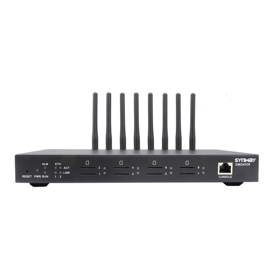
Support of Ping and Tracert tests based on WEB. SysLog Type Three options available: ERROR, WARNING, INFO. 1.3 Hardware Description The wireless gateway supports two LANs and adopts an external 12V power supply. See below SMG Series Wireless Gateway User Manual (Version 1.8.0) Page 4... - Page 10 Channel Indicator Figure 1-2 SMG4008 Front View Power Network Port Figure 1-3 SMG4008 Rear View Alarm Indicator Run Indicator SIM Card Slot SIM Card Slot Indicator Figure 1-4 SMG4016 Front View SMG Series Wireless Gateway User Manual (Version 1.8.0) Page 5...
- Page 11 Auto MDI/MDIX Supported Built-in Link indicator and ACTIVE indicator. For more details, refer to 1.4 Indicator Info Amount: 4, 8, 16*4, 32*4 SIM Card Slot Network Supported: GSM, WCDMA, CDMA, VoLTE SMG Series Wireless Gateway User Manual (Version 1.8.0) Page 6...
-
Page 12: Indicator Info
System is starting. Flash slowly Device is normal. Go out Device is normal. Upon startup: Device is normal. Alarm Indicator Light up In runtime: Device is abnormal. Flash Device is abnormal. Note: SMG Series Wireless Gateway User Manual (Version 1.8.0) Page 7... - Page 13 During runtime, if the alarm indicator lights up or flashes, it indicates that the device goes abnormal. If you cannot figure out and solve the problem by yourself, please contact our technicians for help. Go to Appendix D Technical/sales Support to find the contact way. SMG Series Wireless Gateway User Manual (Version 1.8.0) Page 8...
-
Page 14: Chapter 2 Quick Guide
To use the wireless gateway, you need an external power supply. Insert it to the power interface of the wireless gateway and power it on with 100~240V AC. See the figure below: External Power Supply offers 12V voltage Figure 2-1 Wireless Gateway Power Connection SMG Series Wireless Gateway User Manual (Version 1.8.0) Page 9... - Page 15 Refer to 3.8.2 Port Group for detailed instructions. You may use the default values of other configuration items and are required not to leave „Description‟ empty. SMG Series Wireless Gateway User Manual (Version 1.8.0) Page 10...
- Page 16 If you cannot figure out and solve the problem by yourself, please contact our technicians for help. Otherwise it may lead to a drop in performance or unexpected errors. SMG Series Wireless Gateway User Manual (Version 1.8.0) Page 11...
-
Page 17: Chapter 3 Web Configuration
„System Tools Change Password‟ on the WEB interface. For detailed instructions, refer to 3.11.6 Change Password. After login, you can see the main interface as below. Figure 3-2 Main Interface SMG Series Wireless Gateway User Manual (Version 1.8.0) Page 12... -
Page 18: Operation Info
MAC address of LAN. The three parameters from left to right are IP address, subnet mask and default IP Address gateway of LAN. DNS Server DNS server address of LAN. SMG Series Wireless Gateway User Manual (Version 1.8.0) Page 13... -
Page 19: Port State
Port type on the device. So far, only GSM, WCDMA, CDMA and LTE types are Type supported. Displays the port state in real time. You can move the mouse onto the port state State icon for detailed state information. SMG Series Wireless Gateway User Manual (Version 1.8.0) Page 14... -
Page 20: Call Count
Displays the connection status between the SIM card and the base station. Signal Displays the signal intensity of the wireless module. SIP Reg Status Displays the registration status of the port. 3.2.3 Call Count Figure 3-6 Call Count 1 Interface SMG Series Wireless Gateway User Manual (Version 1.8.0) Page 15... - Page 21 Synway Information Engineering Co., Ltd Figure 3-7 Call Count 2 Interface (4004/4008 Series) SMG Series Wireless Gateway User Manual (Version 1.8.0) Page 16...
- Page 22 Synway Information Engineering Co., Ltd SMG Series Wireless Gateway User Manual (Version 1.8.0) Page 17...
-
Page 23: Sip Message Count
SIP messages that are sent/received or repeatedly sent/received during the period from the startup of the gateway service to the latest open or refresh of the interface. Click Refresh to SMG Series Wireless Gateway User Manual (Version 1.8.0) Page 18... -
Page 24: Quick Config
After configuration, click Back to go back to the Network Settings interface; click Next to enter the Port Settings interface. SMG Series Wireless Gateway User Manual (Version 1.8.0) Page 19... - Page 25 Figure 3-14 Quick Config-Completion Interface Click Back to go back to the Port Settings interface; click Finish to finish the Quick Config wizard and now the gateway can work normally with basic configuration. SMG Series Wireless Gateway User Manual (Version 1.8.0) Page 20...
-
Page 26: Voip Settings
SIP server, NAT Setting is used to configure the parameters for NAT, and Media Settings is to set the RTP port and the payload type. Figure 3-15 VoIP Settings SMG Series Wireless Gateway User Manual (Version 1.8.0) Page 21... -
Page 27: Sip
Sets whether to send the 180 message to respond to the ringing tone when the SIP Send 180 end serves as the called party. Once the feature “Send 180” is enabled, the gateway will reply the 180 message to Called Number SMG Series Wireless Gateway User Manual (Version 1.8.0) Page 22... - Page 28 Only when this feature is enabled will these items Externally Bound Address, Externally Bound Port and Authentication Username be shown. Externally Bound Externally bound IP address for registration. Address Externally Bound Externally bound port for registration. Port SMG Series Wireless Gateway User Manual (Version 1.8.0) Page 23...
-
Page 29: Sip Compatibility
Figure 3-17 SIP Compatibility Setting Interface The table below explains the items shown in Figure 3-17. Item Description There are two optional ways to obtain the called party number: from “To” Field and Obtain CalleeID SMG Series Wireless Gateway User Manual (Version 1.8.0) Page 24... - Page 30 The identifier field of the VOS encryption, which is used to obtain the key of the SIP Identifier encryption. The key to encrypt the SIP signal. Once this feature is enabled, you can encrypt the RTP package. By default it is RTP Encryption disabled. SMG Series Wireless Gateway User Manual (Version 1.8.0) Page 25...
-
Page 31: Sip Station
The bound port to a SIP station must be a wireless port and unique. The username must be the same as that used to register the SIP terminal to the gateway. SMG Series Wireless Gateway User Manual (Version 1.8.0) Page 26... - Page 32 Click Modify in the above figure to modify the configuration of the SIP station. See Figure 3-21. The configuration items on this interface are the same as those on the Add New SIP Station interface. SMG Series Wireless Gateway User Manual (Version 1.8.0) Page 27...
-
Page 33: Sip Server
SIP server. See Figure 3-22 below. Figure 3-22 SIP Server Interface Click Add New to add SIP servers manually. See Figure 3-23. You can configure basic SIP server information on this interface. SMG Series Wireless Gateway User Manual (Version 1.8.0) Page 28... - Page 34 Click Modify in the above figure to modify the configuration of the SIP server. See Figure 3-25. The configuration items on this interface are the same as those on the Add New SIP Server interface. SMG Series Wireless Gateway User Manual (Version 1.8.0) Page 29...
-
Page 35: Nat Setting
After configuration, click Save to save your settings into the gateway or click Reset to restore the configurations. Figure 3-26 NAT Setting Interface The table below explains the items shown in Figure 3-26. SMG Series Wireless Gateway User Manual (Version 1.8.0) Page 30... - Page 36 Rport so as to use them for the following Auto Detect NAT IP communication. By default, this feature is disabled. Note: This feature gets valid only when Rport is enabled. SMG Series Wireless Gateway User Manual (Version 1.8.0) Page 31...
-
Page 37: Media
RFC2833, In-band and Signaling, with the default value of RFC2833. Payload of the RFC2833 formatted DTMF signals on the IP channel. Range of RFC2833 Payload value: 90~127, with the default value of 101. SMG Series Wireless Gateway User Manual (Version 1.8.0) Page 32... - Page 38 Set the minimum threshold for the energy processed by AGC. Signals below this Minimum Input threshold will not be processed by AGC. Range of value: -60~ -25, calculated by Energy dB, with the default value of -60. SMG Series Wireless Gateway User Manual (Version 1.8.0) Page 33...
-
Page 39: Advanced Settings
VPN makes use of the tunnel technology to transport the data, and the methods of user authentication and data encryption to prevent the data being read and distorted when they are transported on the public network. SMG Series Wireless Gateway User Manual (Version 1.8.0) Page 34... -
Page 40: Network
After configuration, click Save to save the above settings into the gateway or click Reset to restore the configurations. After changing the IP address, you shall log in the gateway again using your new IP address. SMG Series Wireless Gateway User Manual (Version 1.8.0) Page 35... -
Page 41: System Param
See Figure 3-30 for the System Parameters Setting interface. The table below explains the items shown in the above figure. Item Description WEB Port The port which is used to access the gateway via WEB. The default value is 80. SMG Series Wireless Gateway User Manual (Version 1.8.0) Page 36... - Page 42 Clear Call Count 2 When this feature is enabled, the gateway will clear the data of Call Count 2 upon its after Restart restart. By default this feature is disabled. SMG Series Wireless Gateway User Manual (Version 1.8.0) Page 37...
-
Page 43: Service Config
Set the waiting time of the channel before it goes into the idle state after the call Waiting for Idle Time finishes. The default value is 1500ms, and the value range is 0~60000. SMG Series Wireless Gateway User Manual (Version 1.8.0) Page 38... - Page 44 Sets whether to enable the mode of non-linear processing. By default, this feature is Processing enabled. Fixed Window Size Sets the size of the window for the fixed cancellation. Moving Window Sets the size of the window for the moving cancellation. Size SMG Series Wireless Gateway User Manual (Version 1.8.0) Page 39...
-
Page 45: Dialing Rule
Add New button on the bottom right corner. See Figure 3-33 for the dialing rule adding interface. Figure 3-33 Add New Dialing Rule SMG Series Wireless Gateway User Manual (Version 1.8.0) Page 40... - Page 46 05, 06, 07, 08 or 09 Number 120。 Number 110, 112, 113, 114, 115, 116, 117, 11[0,2-9] 118 or 119 111xx Any 5-digit number starting with 111 123xx Any 5-digit number starting with 123 SMG Series Wireless Gateway User Manual (Version 1.8.0) Page 41...
- Page 47 See Figure 3-35 for the Dialing Rule Configuration interface under the Character mode. You can edit the dialing rule list to add a new one or modify an old one. The exact meaning of each rule element is described on the page. SMG Series Wireless Gateway User Manual (Version 1.8.0) Page 42...
-
Page 48: Function Key
Click Save to save your settings into the gateway. SMG Series Wireless Gateway User Manual (Version 1.8.0) Page 43... -
Page 49: Cue Tone
By default, there is no available color ring on the gateway. See Figure 3-38. Click Upload to upload a new color ring manually. Follow Figure 3-39 to upload the required color ring file to the gateway. SMG Series Wireless Gateway User Manual (Version 1.8.0) Page 44... - Page 50 To delete a color ring, check the checkbox before the corresponding index in Figure 3-40 and click the Delete button. Check All means to select all available items on the current page; Uncheck SMG Series Wireless Gateway User Manual (Version 1.8.0) Page 45...
-
Page 51: Qos
Sets the priority of the control premium for QoS. A control premium QoS with a Control Premium QoS bigger value has a higher priority. The value range is 0~63, with the default value of SMG Series Wireless Gateway User Manual (Version 1.8.0) Page 46... -
Page 52: Tone Generator
The value range of the tone energy herein above is -12~17, calculated by dB, with the default value of 0. SMG Series Wireless Gateway User Manual (Version 1.8.0) Page 47... -
Page 53: Cdr Query
Click Query to query the CDR information corresponds to the above settings. Figure 3-45 CDR Information Interface Note: This page will appear only when the CDR feature is enabled (set in 3.5.2 System Param). 3.5.11 VPN SMG Series Wireless Gateway User Manual (Version 1.8.0) Page 48... -
Page 54: Wireless Settings
Short Message, IMEI (GSM&WCDMA series), USSD (GSM&WCDMA series), Email, SIM Card, PIN Manage, BS Select (GSM series), Networking Setting (WCDMA series), AMD (CDMA series) and Hidden CallerID (WCDMA series). See Figure 3-48, Figure 3-49 and Figure 3-50. SMG Series Wireless Gateway User Manual (Version 1.8.0) Page 49... - Page 55 Synway Information Engineering Co., Ltd Figure 3-48 Wireless Settings for GSM Figure 3-49 Wireless Settings for WCDMA Figure 3-50 Wireless Settings for CDMA SMG Series Wireless Gateway User Manual (Version 1.8.0) Page 50...
-
Page 56: Basic Parameters
Synway Information Engineering Co., Ltd 3.6.1 Basic Parameters Figure 3-51 Basic Parameters Setting Interface for GSM SMG Series Wireless Gateway User Manual (Version 1.8.0) Page 51... - Page 57 Synway Information Engineering Co., Ltd Figure 3-52 Basic Parameters Setting Interface for WCDMA SMG Series Wireless Gateway User Manual (Version 1.8.0) Page 52...
- Page 58 Synway Information Engineering Co., Ltd Figure 3-53 Basic Parameters Setting Interface for CDMA SMG Series Wireless Gateway User Manual (Version 1.8.0) Page 53...
- Page 59 Remote Transmission. Sets the transmission intensity of the DTMF. The default values for the GSM DTMF Transmission Intensity gateway and the WCDMA gateway are respectively 6 and 1. SMG Series Wireless Gateway User Manual (Version 1.8.0) Page 54...
- Page 60 FWD Unreachable. The former box is used to set the service No, Set/Cancel Service Number for while the latter one is to cancel the service No,. FWD on Busy, Set/Cancel SMG Series Wireless Gateway User Manual (Version 1.8.0) Page 55...
-
Page 61: Wireless Param
See Figure 3-55 for the Wireless Parameters Configuration interface. Click Modify in Figure 3-55 to modify the properties of the corresponding module. See Figure 3-56 for the Wireless Parameters Modification interface. SMG Series Wireless Gateway User Manual (Version 1.8.0) Page 56... - Page 62 The volume of the voice from IP to GSM/WCDMA/CDMA. By default, the value for IP->GSM(WCDMA/CDMA) GSM is 3; the value for WCDMA is 10000; the value for CDMA is 1; the value for Voice Volume SIMCOM is 10400. SMG Series Wireless Gateway User Manual (Version 1.8.0) Page 57...
-
Page 63: Call Forwarding
Note: Be sure to disable the Call Waiting feature before using it. FWD on No Reply Sets whether to enable the feature of FWD on no reply and the FWD number if it is SMG Series Wireless Gateway User Manual (Version 1.8.0) Page 58... -
Page 64: Short Message
It will take some time to apply the settings, and you can check the result in the „FWD Setting Status‟ column. Click Reset to restore the configurations, or click Cancel to cancel the settings. Figure 3-58 Wireless Service Modification Interface 3.6.4 Short Message SMG Series Wireless Gateway User Manual (Version 1.8.0) Page 59... - Page 65 Click Outbox in Figure 3-59 to go into the SMS Sending interface. See Figure 3-63. Such information as the send status of the SMS, the remote cell phone number, the time, and the content will be displayed on this page. SMG Series Wireless Gateway User Manual (Version 1.8.0) Page 60...
- Page 66 Click Send SMS in Figure 3-59 to go into the Send SMS interface. See Figure 3-64. Figure 3-64 Send SMS Interface The table below explains the configuration items on the Send SMS interface. Item Description SMG Series Wireless Gateway User Manual (Version 1.8.0) Page 61...
-
Page 67: Imei
Figure 3-66 IMEI Manual Modification Interface The default IMEI information will be displayed after clicking Initial Value in Figure 3-66, you can save and use it according to your requirement. SMG Series Wireless Gateway User Manual (Version 1.8.0) Page 62... -
Page 68: Ussd
Note: This configuration is unavailable for CDMA module. 3.6.6 USSD Figure 3-68 USSD Setting Interface See Figure 3-68 for the USSD Setting interface. The table below explains the items shown in the above figure. SMG Series Wireless Gateway User Manual (Version 1.8.0) Page 63... -
Page 69: Email
Note: This configuration is unavailable for CDMA module. 3.6.7 Email Figure 3-69 Email Setting Interface See Figure 3-69 for the Email Setting interface. The table below explains the configuration items on the Email Setting interface. Item Description SMG Series Wireless Gateway User Manual (Version 1.8.0) Page 64... - Page 70 Sets whether to receive a return receipt telling the mail is sent successfully or not. After configuration, click Save to save the settings into the gateway or click Reset to reset the settings. SMG Series Wireless Gateway User Manual (Version 1.8.0) Page 65...
-
Page 71: Sim Card
SIM card which is ever in Using state at first will switch to Exist state. Click Modify to modify the parameters. See Figure 3-71. Figure 3-71 SIM Card Management Interface The table below explains the items shown in the above figure. SMG Series Wireless Gateway User Manual (Version 1.8.0) Page 66... -
Page 72: Pin Manage
See Figure 3-72 for the PIN Manage interface, which display the status of the SIM card and the setting status of PIN and PUK. Click Modify to go into the modification interface. See Figure 3-73. Figure 3-73 PIN Manage Modification Interface SMG Series Wireless Gateway User Manual (Version 1.8.0) Page 67... - Page 73 Click Modify in Figure 3-76 to unlock the SIM card or modify the PIN. See the figure below. Figure 3-77 Lock SIM Card or Modify PIN Interface The SIM card will also be locked and cannot make incoming/outgoing calls if you input a wrong SMG Series Wireless Gateway User Manual (Version 1.8.0) Page 68...
-
Page 74: Bs Select
Reset to restore the configurations. Click Cancel to cancel the modification. Note: The SIM card will be locked forever if you input a wrong PUK more than 10 times. You need to insert a new card. 3.6.10 BS Select SMG Series Wireless Gateway User Manual (Version 1.8.0) Page 69... - Page 75 Select the serial number and click the Lock button behind to lock the base station Manual Lock manually. Thus, the SIM card will connect to the locked base station randomly. SMG Series Wireless Gateway User Manual (Version 1.8.0) Page 70...
-
Page 76: Networking Settings
SIM card, such as the time to start accessing the network, the consumed flow, etc. Click Modify in Figure 3-82 to go into the Networking Settings Modification SMG Series Wireless Gateway User Manual (Version 1.8.0) Page 71... - Page 77 Click Save to save the above settings into the gateway or click Reset to restore the configurations. Click Cancel to cancel the modification. Note: This configuration is only supported by the WCDMA and LTE modules. SMG Series Wireless Gateway User Manual (Version 1.8.0) Page 72...
-
Page 78: Amd
Continuous Tones Shortest Voice Duration Sets the shortest duration when the voice goes into the High voltage state, at ON State calculated by ms, with the default value of 150. SMG Series Wireless Gateway User Manual (Version 1.8.0) Page 73... -
Page 79: Hidden Callerid
This feature requires the support of the operator. Select the port and click Open to enable the feature, and click Close to disable it. Note: This configuration is only supported by the WCDMA module. SMG Series Wireless Gateway User Manual (Version 1.8.0) Page 74... -
Page 80: Call Management
Figure 3-88 Balance Query Interface Via the Balance Query interface, you can query the balance of a designated cell phone number. Click Modify to modify the query mode. See the modification interface below. SMG Series Wireless Gateway User Manual (Version 1.8.0) Page 75... - Page 81 Click Cancel to cancel the modification. Click Test to set a balance query strategy, and then execute it to test the balance query feature. And this can help to set a proper balance SMG Series Wireless Gateway User Manual (Version 1.8.0) Page 76...
-
Page 82: Port Timer
Click Modify for each port in Figure 3-91 to modify the timer settings. See Figure 3-92. SMG Series Wireless Gateway User Manual (Version 1.8.0) Page 77... - Page 83 72s, thus, the gateway will consider the call time as 90s. Time Limit on a Single Sets whether to enable the time limit on a single call. Call Max Call Time Sets the maximum time length of a call. SMG Series Wireless Gateway User Manual (Version 1.8.0) Page 78...
-
Page 84: Name List Timer
Name List Timer Rule. You can add the timing rule to count the call time for the port. Click Add New in Figure 3-93 to add a timing rule. See Figure 3-94. SMG Series Wireless Gateway User Manual (Version 1.8.0) Page 79... - Page 85 Return to cancel the settings. After adding the timing rules, click Setting button on the up right corner in Figure 3-93 to set the timing rule for each port. See Figure 3-95 for the setting interface. SMG Series Wireless Gateway User Manual (Version 1.8.0) Page 80...
-
Page 86: Tel To Ip Auto Route
Figure 3-96 TelIP Auto Route Settings Interface The table below explains the configuration items shown in the above figure: Item Description Route Holding Time Sets the valid time of the route. SMG Series Wireless Gateway User Manual (Version 1.8.0) Page 81... -
Page 87: Blacklist
Hang up directly and Hang up after ringing, with the default value of Hang up directly. Click Save to save the settings into the gateway, click Reset to restore the configurations. SMG Series Wireless Gateway User Manual (Version 1.8.0) Page 82... -
Page 88: Sms Count
Modify for each port in Figure 3-98 to modify the SMS count settings. See Figure 3-99. Figure 3-99 SMS Count Configuration Interface The table below explains the configuration items shown in the above figure: Item Description SMG Series Wireless Gateway User Manual (Version 1.8.0) Page 83... -
Page 89: Auto Function
See Figure 3-100 for the Auto Function Settings interface. You can set via this interface to implement automatic calls and SMS from port to port in some special conditions. The table below explains the configuration items shown in the above figure: Item Description SMG Series Wireless Gateway User Manual (Version 1.8.0) Page 84... -
Page 90: Port Charge
Port-to-port Call or Auto Send SMS will be triggered. Click Save to save the settings into the gateway, click Reset to restore the configurations. 3.7.8 Port Charge SMG Series Wireless Gateway User Manual (Version 1.8.0) Page 85... - Page 91 Billing Cycle Sets the billing cycle for the port. Clear Sets the time node to clear the charge. Set Spent Amount Sets the spent amount of call fees for the port. SMG Series Wireless Gateway User Manual (Version 1.8.0) Page 86...
-
Page 92: Port Settings
See Figure 3-104 for the Port Settings interface. The list in the above figure shows the feature and properties of each port. Click Modify in Figure 3-104 to modify the properties of the corresponding port. See Figure 3-105 for the Port Modification interface. SMG Series Wireless Gateway User Manual (Version 1.8.0) Page 87... - Page 93 Port 8 is 8008. Registration password of the port. To register a port to the SIP server, both items SIP Password Account and Password must be filled in. SMG Series Wireless Gateway User Manual (Version 1.8.0) Page 88...
- Page 94 Or you can click Batch Modify in Figure 3-104 to modify several pieces of port settings at the same time. See Figure 3-106 below for the Port Batch Modification interface. SMG Series Wireless Gateway User Manual (Version 1.8.0) Page 89...
- Page 95 The rule for batch setting the authentication password, including Increase, Batch Rule Decrease and All Same three options. Authentication Password Sets the increase or decrease step size of the authentication password in the batch Batch Step Size setting. SMG Series Wireless Gateway User Manual (Version 1.8.0) Page 90...
-
Page 96: Port Group
See Figure 3-108 for the port group adding interface. Note that a port which has been occupied by one port group cannot be chosen by others. Figure 3-108 Add New Port Group SMG Series Wireless Gateway User Manual (Version 1.8.0) Page 91... - Page 97 Group is set to No, the value of this item is Unregistered; when Register Port Group is set to Yes, the value of this item may be Failed or Registered. SMG Series Wireless Gateway User Manual (Version 1.8.0) Page 92...
- Page 98 Click Modify in Figure 3-107 to modify the properties of a port group. See Figure 3-109 for the Port Group Modification interface. The configuration items on this interface are the same as those on the Add New Port Group interface. SMG Series Wireless Gateway User Manual (Version 1.8.0) Page 93...
-
Page 99: Route Settings
Route Settings is used to specify the routing rules for calls on two directions: IPTel/IP and TelIP. See Figure 3-110. Figure 3-110 Route Settings 3.9.1 Routing Parameters Figure 3-111 Routing Parameters Configuration Interface SMG Series Wireless Gateway User Manual (Version 1.8.0) Page 94... -
Page 100: Ip To Tel/Ip
Under the Standard mode, click Add New to add them manually. See Figure 3-113. You may use the default values of all the configuration items herein. Figure 3-113 Add New Routing Rule (IPTel/IP) SMG Series Wireless Gateway User Manual (Version 1.8.0) Page 95... - Page 101 IP address to a corresponding port based on its number. Press the Add New button on the bottom right corner of the list to add a new routing rule. Figure 3-114 IPTel/IP Routing Rule Configuration Interface SMG Series Wireless Gateway User Manual (Version 1.8.0) Page 96...
-
Page 102: Tel To Ip
The TelIP routing rule configuration has two modes: Standard and Character. Under the Standard mode, click Add New to add them manually. See Figure 3-117. You may use SMG Series Wireless Gateway User Manual (Version 1.8.0) Page 97... - Page 103 CallerID/CalleeID prefixes can be added simultaneously. They are separated by “:”. Destination IP, IP address and port number of the remote end to which the call will be routed. Destination Port SMG Series Wireless Gateway User Manual (Version 1.8.0) Page 98...
-
Page 104: Number Manipulation
Figure 3-119 TelIP Routing Rule Configuration Interface (Character) 3.10 Number Manipulation Number Manipulation includes four parts: IPTel/IP CallerID, IPTel/IP CalleeID, TelIP CallerID and TelIP CalleeID. See Figure 3-120. SMG Series Wireless Gateway User Manual (Version 1.8.0) Page 99... -
Page 105: Ip To Tel/Ip Callerid
Add New button on the bottom right corner of the list in the above figure. See Figure 3-122 for the IPTel/IP CallerID manipulation rule adding interface. You may use the default values of all the configuration items herein. SMG Series Wireless Gateway User Manual (Version 1.8.0) Page 100... - Page 106 More information about each number manipulation rule, with the default value of Description default. IP address from where the call is initiated. This item can be set to a specific IP Call Initiator address or “*” which indicates any IP address. SMG Series Wireless Gateway User Manual (Version 1.8.0) Page 101...
- Page 107 IPTel/IP CallerID manipulation rule modification interface. The configuration items on this interface are the same as those on the Add IP Tel/IP CallerID Manipulation Rule interface. Note that the item Index cannot be modified. SMG Series Wireless Gateway User Manual (Version 1.8.0) Page 102...
- Page 108 You can edit the number manipulation rule list to add a new one or modify an old one. The exact meaning of each element of the rule is described on the page. SMG Series Wireless Gateway User Manual (Version 1.8.0) Page 103...
-
Page 109: Ip To Tel/Ip Calleeid
Figure 3-126, Figure 3-127 for IPTel/IP CalleeID Manipulation interface. The configuration items on this interface are the same as those on IP Tel/IP CallerID Manipulation Interface (Figure 3-123). Figure 3-126 IPTel/IP CalleeID Manipulation Interface(Standard) SMG Series Wireless Gateway User Manual (Version 1.8.0) Page 104... -
Page 110: Tel To Ip Callerid
Add New button on the bottom right corner of the list in the above figure. See Figure 3-129 for the TelIP CallerID manipulation rule adding interface. You may use the default values of all the other configuration items herein. SMG Series Wireless Gateway User Manual (Version 1.8.0) Page 105... - Page 111 ‟,‟ is used to separate characters or character ranges, representing alternatives.) For example, 057[1-3,6] represents the string 0571, 0572, 0573 or 0576. Also these items can be set to “*” which SMG Series Wireless Gateway User Manual (Version 1.8.0) Page 106...
- Page 112 TelIP CallerID manipulation rule modification interface. The configuration items on this interface are the same as those on the Add Tel IP CallerID Manipulation Rule interface. Note that the item Index cannot be modified. SMG Series Wireless Gateway User Manual (Version 1.8.0) Page 107...
- Page 113 The exact meaning of each element of the rule is described on the page. SMG Series Wireless Gateway User Manual (Version 1.8.0) Page 108...
-
Page 114: Tel To Ip Calleeid
Figure 3-133 for the TelIP CalleeID manipulation interface. The configuration items on this interface are the same as those on Tel IP CallerID Manipulation Interface (Figure 3-128). Figure 3-132 TelIP CalleeID Manipulation Interface (Standard) SMG Series Wireless Gateway User Manual (Version 1.8.0) Page 109... -
Page 115: System Tools
System Tools is mainly for gateway maintenance. It provides such features as change password, data backup and connectivity check. See Figure 3-134 for details. Figure 3-134 System Tools 3.11.1 Upgrade SMG Series Wireless Gateway User Manual (Version 1.8.0) Page 110... - Page 116 After a successful uploading of the file, the gateway will start to upgrade the system. See Figure 3-137 and you can learn the detailed upgrading information from the upgrade information box at the bottom. SMG Series Wireless Gateway User Manual (Version 1.8.0) Page 111...
-
Page 117: Signaling Capture
Note: Please contact our technicians if you need to downgrade the gateway to an old version. An improper operation may cause unexpected problems. 3.11.2 Signaling Capture Figure 3-138 Signaling Capture Interface See Figure 3-138 for the Signaling Capture interface. Packet capture contains Signaling Packet SMG Series Wireless Gateway User Manual (Version 1.8.0) Page 112... -
Page 118: Data Recording
See Figure 3-139 for the Data Recording interface. Click Start to start the recording. Click Stop to stop the recording. Click Download to download the recorded data. 3.11.4 Call Log Figure 3-140 Call Log Interface SMG Series Wireless Gateway User Manual (Version 1.8.0) Page 113... -
Page 119: Operation Log
IP channels, and Call from Port displays the call log information generated on the port you select. All the SIP related information will be displayed in SIP Log. 3.11.5 Operation Log Figure 3-142 Operation Log Interface SMG Series Wireless Gateway User Manual (Version 1.8.0) Page 114... -
Page 120: Change Password
See Figure 3-144 for the backup and upload interface. To back up the configuration file to your PC, just click Backup. To upload a configuration file, select it via Browse… and click Upload. SMG Series Wireless Gateway User Manual (Version 1.8.0) Page 115... -
Page 121: Factory Reset
3-146. The gateway will overwrite the current configurations with the uploaded data after restart. Click Cancel to cancel this upload directly. Figure 3-146 Configuration File Uploading Interface 3.11.8 Factory Reset Figure 3-147 Factory Reset Interface SMG Series Wireless Gateway User Manual (Version 1.8.0) Page 116... -
Page 122: Restart
5s. As the feature „Automatically restart the service if undetected‟ is enabled, the service application will restart automatically if it is not detected by the gateway guard application. By default, this feature is enabled. SMG Series Wireless Gateway User Manual (Version 1.8.0) Page 117... -
Page 123: Centralized Manage
The description displayed on Synway DCMS after the gateway is registered to Gateway Description Synway DCMS, giving an easy identification of the gateway in device grouping. It is valid only when Synway DCMS is selected The status of the connection between the gateway and the centralized Working Status management server. -
Page 124: Ping Test
The information returned during the Ping test, helping you to learn the network Info connection status between the gateway and the destination address. After configuration, click Start to execute the Ping test; click End to terminate it immediately. SMG Series Wireless Gateway User Manual (Version 1.8.0) Page 119... -
Page 125: Tracert Test
The information returned during the Tracert test, helping you to learn the detailed Info information about the jumps between the gateway and the destination address. After configuration, click Start to execute the Tracert test; click End to terminate it immediately. SMG Series Wireless Gateway User Manual (Version 1.8.0) Page 120... -
Page 126: Wireless Network Test
Conversion Time Length The time length of the conversion Call Times The times of the testing call After configuration, click Start to execute the test; click Stop to terminate it immediately. SMG Series Wireless Gateway User Manual (Version 1.8.0) Page 121... -
Page 127: Access Control
Inverse means to uncheck the selected items and check the unselected. To clear all access control commands at a time, click the Clear All button in Figure 3-154. Note: SMG Series Wireless Gateway User Manual (Version 1.8.0) Page 122... -
Page 128: Device Lock
See Figure 3-157 for the Device Lock Configuration interface. This feature is unopened. If you need use it, please contact our technicians to apply for a special link to access the gateway again. SMG Series Wireless Gateway User Manual (Version 1.8.0) Page 123... -
Page 129: Appendix A Technical Specifications
VoLTE network so that they provide quick Flow control unsupported call establishment and stay unaffected by the Base Station capacity. Note: Follow the above settings to configure the serial port; or it may work abnormally. SMG Series Wireless Gateway User Manual (Version 1.8.0) Page 124... -
Page 130: Appendix B Troubleshooting
SIP devices or PSTN telephones, Q5. Which RTP codecs are supported by the gateway? At present, the supported RTP codecs are: G.711A, G.711u, G.729, G.723, G.722, AMR and iLBC. SMG Series Wireless Gateway User Manual (Version 1.8.0) Page 125... -
Page 131: Appendix C About Vpn
Step 2: Select a certificate from the client, that is, a configuration file with the suffix of .conf, and then click the „Upload‟ button. The following dialog will appear. SMG Series Wireless Gateway User Manual (Version 1.8.0) Page 126... - Page 132 (Note: Set as a flag to warn about replayed data packages.) ns-cert-type server comp-lzo (Note: Use the Izo compression which is consistent with the server.) verb 3 ;tls-client SMG Series Wireless Gateway User Manual (Version 1.8.0) Page 127...
- Page 133 After the VPN featured is opened at the server, use your PCs to connect as a test. If two PCs can PING through each other, it means the server works normally. SMG Series Wireless Gateway User Manual (Version 1.8.0) Page 128...
- Page 134 The system time of the wireless gateway must be consistent with that of the server, or the connection may sometimes fails. After enabling the VPN feature successfully, you can use the virtual IP of the gateway to make calls in both directions IP-->tel and tel-->IP. SMG Series Wireless Gateway User Manual (Version 1.8.0) Page 129...
-
Page 135: Appendix D Technical/Sales Support
Synway Information Engineering Co., Ltd Appendix D Technical/sales Support Thank you for choosing Synway. Please contact us should you have any inquiry regarding our products. We shall do our best to help you. Headquarters Synway Information Engineering Co., Ltd http://www.synway.net/ 9F, Synway D&R Center, No.3756, Nanhuan Road, Binjiang District,...
Need help?
Do you have a question about the SMG Series and is the answer not in the manual?
Questions and answers