Synway SMG Series User Manual
Digital gateway
Hide thumbs
Also See for SMG Series:
- User manual (178 pages) ,
- User manual (133 pages) ,
- User manual (107 pages)
Table of Contents
Advertisement
Quick Links
Download this manual
See also:
User Manual
Advertisement
Table of Contents

Related Manuals for Synway SMG Series


Summary of Contents for Synway SMG Series
- Page 1 All manuals and user guides at all-guides.com Synway SMG Series Digital Gateway SMG2030 SMG2060 SMG2120 SMG3008 SMG3016 Digital Gateway Version 1.6.0 Synway Information Engineering Co., Ltd www.synway.net...
-
Page 2: Table Of Contents
TUP Number Parameter ..................53 3.5.4 ISUP ........................55 3.5.5 ISUP Number Parameter ..................57 3.5.6 Original CalleeID Pool .................... 60 3.5.7 Redirecting Number Pool ..................61 3.5.8 SS7 Server ......................63 SMG Series Digital Gateway User Manual (Version 1.6.0) Page i... - Page 3 Configurations for Branch A .................. 119 4.1.3 Configurations for Branch B .................. 122 Application 2 ....................126 4.2.1 Configurations for Headquarters ................126 4.2.2 Configurations for Branches ................. 129 Appendix A Technical Specifications ..........130 SMG Series Digital Gateway User Manual (Version 1.6.0) Page ii...
- Page 4 Appendix B Troubleshooting ............131 Appendix C ISUP (ISDN) Pending Cause to SIP Status Code ..132 Appendix D TUP Pending Cause to SIP Status Code ..... 134 Appendix E Technical/sales Support ..........135 SMG Series Digital Gateway User Manual (Version 1.6.0) Page iii...
-
Page 5: Copyright Declaration
Synway has made every effort to ensure the accuracy of this document but does not guarantee the absence of errors. Moreover, Synway assumes no responsibility in obtaining permission and authorization of any third party patent, copyright or product involved in relation to the use of this document. -
Page 6: Revision History
Add description on the new series SMG3016 Version 1.5.1 2015-01 Add description on the new series SMG3008 Version 1.6.0 2015-03 New revision Note: Please visit our website http://www.synway.net to obtain the latest version of this document. SMG Series Digital Gateway User Manual (Version 1.6.0) Page v... -
Page 7: Chapter 1 Product Introduction
Chapter 1 Product Introduction Thank you for choosing Synway SMG Series Digital Gateway! The Synway SMG series digital gateway products (hereinafter referred to as ‘SMG digital gateway’) are mainly used for connecting PSTN or enterprise PBX with the IP telephony network or IP PBX. -
Page 8: Feature List
Support of configurations through the WEB user interface Language Chinese, English Support of user interface, gateway service, kernel and firmware upgrades based Software Upgrade on WEB Tracking Test Support of Ping and Tracert tests based on WEB SMG Series Digital Gateway User Manual (Version 1.6.0) Page 2... -
Page 9: Hardware Description
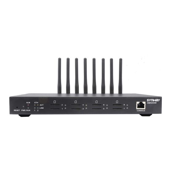
See below figures for SMG3000 series appearance: LAN2 Indicator LAN1 Indicator Console Port Alarm Indicator Power 1 Indicator Reset Button PCM Indicator Power 2 Indicator Run Indicator Figure 1-5 Front View SMG Series Digital Gateway User Manual (Version 1.6.0) Page 3... - Page 10 The orange LED on the right of LAN, whose flashing tells data are being ACT Indicator transmitted. The green LED on the right of E1/T1 interface lights up and keeps on after the E1/T1 Indicators E1/T1 module is successfully synchronized. SMG Series Digital Gateway User Manual (Version 1.6.0) Page 4...
-
Page 11: Alarm Info
During runtime, if the alarm indicator lights up or flashes, it indicates that the device goes abnormal. If you cannot figure out and solve the problem by yourself, please contact our technicians for help. Go to Appendix E Technical/sales Support to find the contact way. SMG Series Digital Gateway User Manual (Version 1.6.0) Page 5... -
Page 12: Chapter 2 Quick Guide
The synchronization indicator starts working only after the device is powered on and successfully initialized. TTip Transmit TRing RTip Receive RRing SMG Series Digital Gateway User Manual (Version 1.6.0) Page 6... - Page 13 DPC. Fill in „SP Code‟ with the signaling point code of the remote end (i.e. signaling destination), select the linkset configured in Step 3 for „Linkset‟ and use the default values for the other configuration items. After modification, click ‘Save’. SMG Series Digital Gateway User Manual (Version 1.6.0) Page 7...
- Page 14 Note: After configuring the ISDN interface, you shall restart the service to validate the settings. Refer to 3.12.17 Restart for detailed instructions. SS1: The configuration interface related to SS1 is SS1. On your initial use of the SMG digital gateway, SMG Series Digital Gateway User Manual (Version 1.6.0) Page 8...
- Page 15 5060. Provided 123 is a number which conforms to the number receiving rule of the remote device. Initiate a call from SIP terminal 0 to the IP address 192.168.0.101 (in the format: 123@192.168.0.101) and you can establish a call conversation via PCM[1] to SMG Series Digital Gateway User Manual (Version 1.6.0) Page 9...
- Page 16 During runtime, if the alarm indicator lights up or flashes, it indicates that the device goes abnormal. If you cannot figure out and solve the problem by yourself, please contact our SMG Series Digital Gateway User Manual (Version 1.6.0) Page 10...
- Page 17 All manuals and user guides at all-guides.com Synway Information Engineering Co., Ltd technicians for help. Otherwise it may lead to a drop in performance or unexpected errors. SMG Series Digital Gateway User Manual (Version 1.6.0) Page 11...
-
Page 18: Chapter 3 Web Configuration
„System Tools Change Password‟ on the WEB interface. For detailed instructions, refer to 3.12.15 Change Password. After login, you can see the main interface as below. Figure 3-2 Main Interface SMG Series Digital Gateway User Manual (Version 1.6.0) Page 12... -
Page 19: Operation Info
See Figure 3-3. Figure 3-3 Operation Info 3.2.1 System Info Figure 3-4 System Info Interface See Figure 3-4 for the system info interface. You can click Refresh to obtain the latest system SMG Series Digital Gateway User Manual (Version 1.6.0) Page 13... - Page 20 Current version of the gateway service. Uboot Current version of Uboot. Kernel Current version of the system kernel on the gateway. Firmware Current version of the firmware on the gateway. SMG Series Digital Gateway User Manual (Version 1.6.0) Page 14...
-
Page 21: Pstn Status
State For Time Slot 0, the channel state indicates the synchronization status of E1/T1. State Color Description SMG Series Digital Gateway User Manual (Version 1.6.0) Page 15... - Page 22 This state indicates the signaling time slot on this Unused E1/T1 is not used. For the other channels, the channel states include: State Icon Description Unusable The channel is unavailable. SMG Series Digital Gateway User Manual (Version 1.6.0) Page 16...
- Page 23 Note: Click Record to start recording on the matched channel. If more than one channels match a condition, only the channel with the largest number among them will be recorded. SMG Series Digital Gateway User Manual (Version 1.6.0) Page 17...
-
Page 24: Ss7 Server
If this item is ticked, the receive/transmit message list will display the SNT Messages messages. Display SNM If this item is ticked, the receive/transmit message list will display the SNM Messages messages. SMG Series Digital Gateway User Manual (Version 1.6.0) Page 18... - Page 25 Status Bar 4: Client information This region displays the information about client IP address and connection state. The table below explains the information items in Status Bar 4. Item Description Client Client number. SMG Series Digital Gateway User Manual (Version 1.6.0) Page 19...
- Page 26 2: FIBR illegal positioning processor failure both ends positioned/ 3: T2 timeout processor ready failure 4: T6 timeout, the positioned/ remote end busy not ready SMG Series Digital Gateway User Manual (Version 1.6.0) Page 20...
- Page 27 Status Bar 7: Runtime Log Runtime log records all MTP3 commands and error information that pops up during the operation. This status bar displays all the log records generated after the digital gateway starts. SMG Series Digital Gateway User Manual (Version 1.6.0) Page 21...
-
Page 28: Call Count
Total number and connection rate of calls on all available tunks Release Cause Reason to release the call. Normal call clearing Total number of the calls which are normally cleared. SMG Series Digital Gateway User Manual (Version 1.6.0) Page 22... -
Page 29: Voip Settings
SIP; SIP Account is used for registering SIP accounts to the SIP server; SIP Trunk Group is to manage SIP trunks by group; and Media is to set the RTP port and the payload type. Figure 3-10 VoIP Settings SMG Series Digital Gateway User Manual (Version 1.6.0) Page 23... -
Page 30: Sip Settings
All manuals and user guides at all-guides.com Synway Information Engineering Co., Ltd 3.3.1 SIP Settings SMG Series Digital Gateway User Manual (Version 1.6.0) Page 24... - Page 31 When this feature is enabled, a corresponding Rport field will be added to the Via Rport message of SIP. By default, it is disabled. Sets whether to enable the DSCP differentiated services code point. By default, it is DSCP disabled. SMG Series Digital Gateway User Manual (Version 1.6.0) Page 25...
-
Page 32: Sip Trunk
New button on the bottom right corner of the list in the above figure. See Figure 3-13 for the SIP trunk adding interface. Figure 3-13 Add New SIP Trunk The table below explains the items shown in Figure 3-13. SMG Series Digital Gateway User Manual (Version 1.6.0) Page 26... -
Page 33: Sip Register
All means to cancel all selections on the current page; Inverse means to uncheck the selected items and check the unselected. To clear all SIP trunks at a time, click the Clear All button in Figure 3-12. 3.3.3 SIP Register SMG Series Digital Gateway User Manual (Version 1.6.0) Page 27... - Page 34 Registration password of the gateway. To register the gateway to the SIP server, Password both configuration items Username and Password should be filled in. Register Address Address of the SIP server to which the SIP trunk is registered. SMG Series Digital Gateway User Manual (Version 1.6.0) Page 28...
- Page 35 Click Modify in Figure 3-17 to modify a SIP register. The configuration items on the SIP Register Modification Interface are the same as those on the Add New SIP Register interface. SMG Series Digital Gateway User Manual (Version 1.6.0) Page 29...
-
Page 36: Sip Account
See Figure 3-19 for the SIP account settings interface. A new SIP account can be added by the Add New button on the bottom right corner of the list in the above figure. See Figure 3-20 for the SMG Series Digital Gateway User Manual (Version 1.6.0) Page 30... - Page 37 Click Modify in Figure 3-19 to modify a SIP account. See Figure 3-21 for the SIP account modification interface. The configuration items on this interface are the same as those on the Add SMG Series Digital Gateway User Manual (Version 1.6.0) Page 31...
-
Page 38: Sip Trunk Group
See Figure 3-22 for SIP trunk group settings interface. A new SIP trunk group can be added by the Add New button on the bottom right corner of the list in the above figure. See Figure 3-23 for the SIP trunk group adding interface. SMG Series Digital Gateway User Manual (Version 1.6.0) Page 32... - Page 39 Click Modify in Figure 3-22 to modify a SIP trunk group. See Figure 3-24 for the SIP trunk group modification interface. The configuration items on this interface are the same as those on the Add New SIP Trunk Group interface. SMG Series Digital Gateway User Manual (Version 1.6.0) Page 33...
- Page 40 Uncheck All means to cancel all selections on the current page; Inverse means to uncheck the selected items and check the unselected. To clear all SIP trunk groups at a time, click the Clear All button in Figure 3-22. SMG Series Digital Gateway User Manual (Version 1.6.0) Page 34...
-
Page 41: Media Settings
RFC2833, In-band and Signaling, with the default value of RFC2833. Payload of the RFC2833 formatted DTMF signals on the IP channel. Range of RFC2833 Payload value: 90~127, with the default value of 101. SMG Series Digital Gateway User Manual (Version 1.6.0) Page 35... - Page 42 3. Range of value: -24~24, calculated by dB, with the default value of 0. Supported CODECs and their corresponding priority for the IP end to establish a call conversation. The table below explains the sub-items: CODEC Priority Sub-item Description SMG Series Digital Gateway User Manual (Version 1.6.0) Page 36...
-
Page 43: Pcm Settings
3.4 PCM Settings PCM Settings includes eight parts: PSTN, Circuit Maintenance, PCM, PCM Trunk, PCM Trunk Group, Number-Receiving Rule, Reception Timeout and Number Attribution. See Figure 3-26. Figure 3-26 PCM Settings SMG Series Digital Gateway User Manual (Version 1.6.0) Page 37... -
Page 44: Pstn
Sets whether to enable the feature of hot back-up for E1, with the default value of Hot Back-up for E1 disable. Gateway IP for Hot Set the IP of the gateway for the hot back-up for E1. Back-up SMG Series Digital Gateway User Manual (Version 1.6.0) Page 38... -
Page 45: Circuit Maintenance
PCM. The table below explains the items shown in the above figure. Item Description PCM No. The number of the PCM, numbered from 0. This item is not configurable. SMG Series Digital Gateway User Manual (Version 1.6.0) Page 39... - Page 46 Click Modify in Figure 3-29 to modify a PCM. See Figure 3-30 for the PCM modification interface. Most configuration items on this interface are the same as those on the PCM Settings interface. SMG Series Digital Gateway User Manual (Version 1.6.0) Page 40...
-
Page 47: Pcm Trunk
See Figure 3-31 for the PCM Trunk Configuration interface. By default, there is no PCM trunk available on the gateway. Click Add New or Batch Add to add them manually. See Figure 3-32, SMG Series Digital Gateway User Manual (Version 1.6.0) Page 41... - Page 48 Figure 3-32 Add PCM Trunk Interface Figure 3-33 PCM Trunk Batch Add Interface The table below explains the items shown in the above figure. Item Description Index The unique index of each PCM trunk SMG Series Digital Gateway User Manual (Version 1.6.0) Page 42...
- Page 49 Uncheck All means to cancel all selections on the current page; Inverse means to uncheck the selected items and check the unselected. To clear all PCM trunks at a time, click the Clear All button in Figure 3-34. SMG Series Digital Gateway User Manual (Version 1.6.0) Page 43...
-
Page 50: Pcm Trunk Group
The unique index of each PCM trunk group, which is mainly used in the Index configuration of routing rules and number manipulation rules to correspond to PCM trunk groups. Description More information about each PCM trunk group. SMG Series Digital Gateway User Manual (Version 1.6.0) Page 44... - Page 51 Uncheck All means to cancel all selections on the current page; Inverse means to uncheck the selected items and check the unselected. To clear all PCM trunk groups at a time, click the Clear All button in Figure 3-36. SMG Series Digital Gateway User Manual (Version 1.6.0) Page 45...
-
Page 52: Number-Receiving Rule
The unique index of each number-receiving rule, which denotes its priority. A Index number-receiving rule with a smaller index value has a higher priority and will be checked earlier while matching. SMG Series Digital Gateway User Manual (Version 1.6.0) Page 46... - Page 53 15 or 18 Any 8-digit number starting with 2, 3, 5, 6 [2-3,5-7]xxxxxxx or 7 Any 8-digit number starting with 81, 82, 8[1-9]xxxxxx 83, 84, 85, 86, 87, 88 or 89 SMG Series Digital Gateway User Manual (Version 1.6.0) Page 47...
-
Page 54: Reception Timeout
Clear All button in Figure 3-39. 3.4.7 Reception Timeout Figure 3-42 Number-receiving Timeout Info Interface See Figure 3-42 for the number-receiving timeout info interface. The table below explains the SMG Series Digital Gateway User Manual (Version 1.6.0) Page 48... - Page 55 Number-receiving Timeout Info Interface. Figure 3-43 Modify Number-receiving Timeout Info After configuration, click Save to save the above settings into the gateway or click Close to cancel the settings. SMG Series Digital Gateway User Manual (Version 1.6.0) Page 49...
-
Page 56: Number Attribution
PCM settings interface is set to SS7-TUP or SS7-ISUP. SS7 Settings includes eight parts: SS7, TUP, TUP Number Param, ISUP, Number Param, Original CalleeID Pool, Redirecting Number Pool and SS7 Server. See Figure 3-45. SMG Series Digital Gateway User Manual (Version 1.6.0) Page 50... -
Page 57: Ss7
If this feature is enabled, two SS7 servers are used at the same time in the system. Dual Gateway The configuration items Master IP and Slave IP are respectively used to set the IP addresses of the master and slave servers. SMG Series Digital Gateway User Manual (Version 1.6.0) Page 51... -
Page 58: Tup
IP to PSTN, you shall set a separate value for the address indicator in the calling case of Original CalleeID line identification field in the IAI message, i.e. Caller Parameter ( with Original CalleeID). By default this configuration item is disabled. SMG Series Digital Gateway User Manual (Version 1.6.0) Page 52... -
Page 59: Tup Number Parameter
TUP. A new TUP number parameter can be added by the Add New button. See Figure 3-49 for the calling party number adding interface. SMG Series Digital Gateway User Manual (Version 1.6.0) Page 53... - Page 60 The configuration items on this interface are the same as those on the Add New Calling Party Number Parameter interface. Figure 3-50 Modify Calling Party Number Parameter SMG Series Digital Gateway User Manual (Version 1.6.0) Page 54...
-
Page 61: Isup
Sets the calling party‟s category indicator in the IAM message. The optional values are: National operator, Ordinary calling subscriber, Calling subscriber with priority, Calling Party’s Category Data call, Test call and Payphone/Others, with the default value of Ordinary calling subscriber. SMG Series Digital Gateway User Manual (Version 1.6.0) Page 55... - Page 62 If the call is not answered within the specified time period, it will be canceled by Time (s) the channel automatically. The default value is 180, calculated by s. SMG Series Digital Gateway User Manual (Version 1.6.0) Page 56...
-
Page 63: Isup Number Parameter
Calling Party Number Parameter and Called Party Number Parameter. A new calling/called party number parameter can be added by the Add New button. See Figure 3-53, Figure 3-54 for the calling/called party number parameter adding interface. SMG Series Digital Gateway User Manual (Version 1.6.0) Page 57... - Page 64 Set whether to enable the feature of setting this parameter only if the original Original CalleeID CalleeID is available. Available After configuration, click Save to save the above settings into the gateway or click Close to cancel the settings. SMG Series Digital Gateway User Manual (Version 1.6.0) Page 58...
- Page 65 Clear All button in Figure 3-52. Note: If there are two or more calling/called party numbers with the same prefix, the one numbered the smallest is valid and all the others become invalid. SMG Series Digital Gateway User Manual (Version 1.6.0) Page 59...
-
Page 66: Original Calleeid Pool
CallerID Prefix numbers or “*” (indicating any string). A string of numbers at the beginning of a called party number, which can be CalleeID Prefix numbers or “*” (indicating any string). SMG Series Digital Gateway User Manual (Version 1.6.0) Page 60... -
Page 67: Redirecting Number Pool
See Figure 3-60 for the Redirecting Number Pool interface, which is used to set the redirecting number in the setup message for all outgoing calls or some calls which contain a specified SMG Series Digital Gateway User Manual (Version 1.6.0) Page 61... - Page 68 The configuration items on this interface are the same as those on the Add New Redirecting Number interface. Note that the item No. cannot be modified. SMG Series Digital Gateway User Manual (Version 1.6.0) Page 62...
-
Page 69: Ss7 Server
When the gateway uses the SS7 signaling, it must run the SS7 server first. See Figure 3-63 for the SS7 configuration interface, where you can set the SS7 server configuration file (Ss7server.ini). Follow the instructions below to accomplish the configurations step by step. SMG Series Digital Gateway User Manual (Version 1.6.0) Page 63... - Page 70 Step 3: Configure signaling links and linksets. See Region 3 in Figure 3-63. The link used to transmit signaling messages between two signaling points is called Signaling SMG Series Digital Gateway User Manual (Version 1.6.0) Page 64...
- Page 71 A new signaling linkset can be added by the Add New button on the bottom right corner of the signaling linkset list. See Figure 3-66 for the new signaling linkset adding interface. SMG Series Digital Gateway User Manual (Version 1.6.0) Page 65...
- Page 72 The signaling point that receives messages is called Destination Point Code (DPC). A new DPC can be added by the Add New button on the bottom right corner of the DPC list. See Figure 3-67 for the new DPC adding interface. SMG Series Digital Gateway User Manual (Version 1.6.0) Page 66...
- Page 73 OPC and the DPC. For the Linkset quasi-associated mode, this item sets the signaling linksets between the OPC and the first STP (signaling transport point). SMG Series Digital Gateway User Manual (Version 1.6.0) Page 67...
- Page 74 Range of the PCM time slots corresponding to CIC. Client number. This configuration item together with PCM determines the local PCM Client in the CIC routing rule. PCM number on the client. SMG Series Digital Gateway User Manual (Version 1.6.0) Page 68...
-
Page 75: Isdn Settings
Users can see the ISDN option in the menu only when the configuration item Signaling Protocol on the PCM settings interface is set to ISDN User Side or ISDN Network Side. See Figure 3-70. SMG Series Digital Gateway User Manual (Version 1.6.0) Page 69... -
Page 76: Isdn
Sets the way to represent channel identification messages on the digital trunk. The Ch Identification optional values are: Number and Time slot diagram, with the default value of Number. SMG Series Digital Gateway User Manual (Version 1.6.0) Page 70... - Page 77 The maximum time waiting for the called party to pick up the call after the channel Maximum Wait Time for state turns to „WaitAnswer‟ during an outgoing call. The default value is 60, Called Party’s Pick up calculated by s. SMG Series Digital Gateway User Manual (Version 1.6.0) Page 71...
-
Page 78: Number Parameter
ISDN. See Figure 3-72 for Number Parameter for ISDN. The configuration items on this interface are the same as those on Number Parameter for SS7 (Figure 3-53, Figure 3-54). SMG Series Digital Gateway User Manual (Version 1.6.0) Page 72... -
Page 79: Redirecting Number
Operation Info PSTN Status. See Figure 3-75 for the gateway adding interface. Figure 3-75 Add New Gateway The table below explains the items shown in above figures. SMG Series Digital Gateway User Manual (Version 1.6.0) Page 73... - Page 80 Click Modify in Figure 3-74 to modify the gateway information. See Figure 3-76 for the gateway modification interface. The configuration items on this interface are the same as those on the Add New Gateway interface. Figure 3-76 Modify Gateway Information SMG Series Digital Gateway User Manual (Version 1.6.0) Page 74...
-
Page 81: Ss1 Settings
ABCD codes, Otherwise, the driver will believe there are undesired dithering signals on the line. SMG Series Digital Gateway User Manual (Version 1.6.0) Page 75... -
Page 82: Fax Settings
3 (local call). Signal) 3.8 Fax Settings See Figure 3-78 for the Fax Settings interface which is used to modify the special fax configurations. Figure 3-78 Fax Settings SMG Series Digital Gateway User Manual (Version 1.6.0) Page 76... -
Page 83: Fax
(Redundancy Error Correction) and t38UDPFEC (Forward Mode Error Correction), with the default value of t38UDPRedundancy. Sets whether to enable the T.30 error correction mode. By default this feature is T.30 Ecm enabled. SMG Series Digital Gateway User Manual (Version 1.6.0) Page 77... -
Page 84: Route Settings
102. 3.9 Route Settings Route Settings is used to specify the routing rules for calls on two directions: IPPSTN and PSTNIP. See Figure 3-81. Figure 3-81 Route Settings SMG Series Digital Gateway User Manual (Version 1.6.0) Page 78... -
Page 85: Routing Parameters
See Figure 3-83 for the IPPSTN routing rule configuration interface. A new routing rule can be added by the Add New button on the bottom right corner of the list in the above figure. See Figure 3-84 for the IPPSTN routing rule adding interface. SMG Series Digital Gateway User Manual (Version 1.6.0) Page 79... - Page 86 The configuration items on this interface are the same as those on the Add New Routing Rule (IP PSTN) interface. Note that the item Index cannot be modified. Figure 3-85 Modify Routing Rule (IPPSTN) SMG Series Digital Gateway User Manual (Version 1.6.0) Page 80...
-
Page 87: Pstn To Ip
PCM trunk group from which the call is initiated. This item can be set to a specific Call Initiator PCM trunk group or PCM Trunk Group [ANY] which indicates any PCM trunk group. SMG Series Digital Gateway User Manual (Version 1.6.0) Page 81... -
Page 88: Number Filter
To clear all routing rules at a time, click the Clear All button in Figure 3-86. 3.10 Number Filter Number Filter includes four parts: Whitelist, Blacklist, Number Pool and Filtering Rule. See Figure 3-89. SMG Series Digital Gateway User Manual (Version 1.6.0) Page 82... -
Page 89: Whitelist
A new CallerID/CalleeID whitelist can be added by the Add New button. See Figure 3-91, Figure 3-92 for CallerID/CalleeID whitelist adding interface. Figure 3-91 Add New CallerIDs in Whitelist Interface SMG Series Digital Gateway User Manual (Version 1.6.0) Page 83... - Page 90 3-94 for CallerIDs/CalleeIDs on the Whitelist Modification interface. The configuration items on this interface are the same as those on the Add New CallerIDs/CalleeIDs in Whitelist interface. The item Group No. cannot be modified. Figure 3-93 Modify CallerIDs in Whitelist SMG Series Digital Gateway User Manual (Version 1.6.0) Page 84...
-
Page 91: Blacklist
The Blacklist Setting interface is almost the same as the Whitelist Setting interface; only the whitelist changes to the blacklist. See Figure 3-95. The configuration items on this interface are the same as those on the Whitelist Setting interface (Figure 3-91, Figure 3-92). SMG Series Digital Gateway User Manual (Version 1.6.0) Page 85... -
Page 92: Number Pool
Click Modify in Figure 3-96 to modify the number pool. See Figure 3-98 for the number pool modification interface. The configuration items on this interface are the same as those on the Add SMG Series Digital Gateway User Manual (Version 1.6.0) Page 86... -
Page 93: Filtering Rule
See Figure 3-99 for the Filtering Rule Setting Interface. A new filtering rule can be added by the Add New button on the bottom right corner of the list in the above figure. See Figure 3-100 for the Filtering Rule Adding interface. SMG Series Digital Gateway User Manual (Version 1.6.0) Page 87... - Page 94 Select a Group No. which is set in the blacklist from the number pool as the CallerID Blacklist pool in blacklist. CalleeID Pool in Select a Group No. which is set in the whitelist from the number pool as the CalleeID Whitelist pool in whitelist. SMG Series Digital Gateway User Manual (Version 1.6.0) Page 88...
- Page 95 The configuration items on this interface are the same as those on the Add New Filtering Rule interface. Figure 3-101 Modify Filtering Rule Interface To delete a filtering rule, check the checkbox before the corresponding index in Figure 3-99 and SMG Series Digital Gateway User Manual (Version 1.6.0) Page 89...
-
Page 96: Number Manipulation
Add New button on the bottom right corner of the list in the above figure. See Figure 3-104 for the IPPSTN CallerID manipulation rule adding interface. SMG Series Digital Gateway User Manual (Version 1.6.0) Page 90... - Page 97 If this item is set to Yes, it indicates that the number manipulation rule is only With Original applicable to the calls with original CalleeID/redirecting number. The default value is CalleeID SMG Series Digital Gateway User Manual (Version 1.6.0) Page 91...
- Page 98 IPPSTN CallerID manipulation rule modification interface. The configuration items on this interface are the same as those on the Add IP PSTN CallerID Manipulation Rule interface. Note that the item Index cannot be modified. SMG Series Digital Gateway User Manual (Version 1.6.0) Page 92...
-
Page 99: Ip To Pstn Calleeid
Figure 3-106 for IPPSTN CalleeID manipulation interface. The configuration items on this interface are the same as those on IP PSTN CallerID Manipulation Interface (Figure 3-103). Figure 3-106 IPPSTN CalleeID Manipulation Interface SMG Series Digital Gateway User Manual (Version 1.6.0) Page 93... -
Page 100: Ip To Pstn Original Calleeid
Add New button on the bottom right corner of the list in the above figure. See Figure 3-109 for the PSTNIP CallerID manipulation rule adding interface. SMG Series Digital Gateway User Manual (Version 1.6.0) Page 94... - Page 101 If this item is set to Yes, it indicates that the number manipulation rule is only With Original applicable to the calls with original CalleeID/redirecting number. The default value is CalleeID SMG Series Digital Gateway User Manual (Version 1.6.0) Page 95...
- Page 102 PSTNIP CallerID manipulation rule modification interface. The configuration items on this interface are the same as those on the Add PSTN IP CallerID Manipulation Rule interface. Note that the item Index cannot be modified. SMG Series Digital Gateway User Manual (Version 1.6.0) Page 96...
-
Page 103: Pstn To Ip Calleeid
Figure 3-111 for the PSTNIP CalleeID manipulation interface. The configuration items on this interface are the same as those on PSTN IP CallerID Manipulation Interface (Figure 3-108). Figure 3-111 PSTNIP CalleeID Manipulation Interface SMG Series Digital Gateway User Manual (Version 1.6.0) Page 97... -
Page 104: Pstn To Ip Original Calleeid
IPPSTN CallerID Pool. It is used to designate the CallerID for outgoing calls and restrict the call amount for each designated callerID at the same time. A new CallerID can be added by the Add New button. See Figure 3-114 for the CallerID adding interface. SMG Series Digital Gateway User Manual (Version 1.6.0) Page 98... -
Page 105: System Tools
3.12 System Tools System Tools is mainly for gateway maintenance. It provides such features as IP modification, time synchronization, data backup, log inquiry and connectivity check. See Figure 3-116 for details. SMG Series Digital Gateway User Manual (Version 1.6.0) Page 99... - Page 106 All manuals and user guides at all-guides.com Synway Information Engineering Co., Ltd Figure 3-116 System Tools SMG Series Digital Gateway User Manual (Version 1.6.0) Page 100...
-
Page 107: Network
By default, this feature is disabled. After configuration, click Save to save the above settings into the gateway or click Reset to SMG Series Digital Gateway User Manual (Version 1.6.0) Page 101... -
Page 108: Management
Also you can set an IP blacklist to forbid all the IPs within it to access the gateway. Sets whether to enable the gateway to be accessed via SSH, with the default value of No. SMG Series Digital Gateway User Manual (Version 1.6.0) Page 102... -
Page 109: Snmp Config
Monitoring Port for SNMP on the gateway. Read-only Community String Community string used for information acquisition. You can query OID (object identification trees) = .1.3.6.1.4.1.2021.51 at the SNMP Client to obtain SMG Series Digital Gateway User Manual (Version 1.6.0) Page 103... -
Page 110: Radius
Spare Server between the gateway and Radius master server. Note: If the port isn‟t designated, the default port 1813 will be used. SMG Series Digital Gateway User Manual (Version 1.6.0) Page 104... - Page 111 Radius server upon the access failure occurs. After configuration, click Save to save the above settings into the gateway or click Reset to restore the configurations. SMG Series Digital Gateway User Manual (Version 1.6.0) Page 105...
-
Page 112: Configuration File
ShConfig.ini; and configurations about the SS7 server are included in Ss7Server.ini. You can modify these configurations on the interface directly, and then click Save to save the above settings into the gateway or click Reset to restore the configurations. SMG Series Digital Gateway User Manual (Version 1.6.0) Page 106... -
Page 113: Signaling Capture
Click Start to start recording data (maximum consecutively recording time: data recording is100 minutes and two-way recording is 1 minutes) on the corresponding port and time slot. Click Stop to stop data recording and download the recorded data. SMG Series Digital Gateway User Manual (Version 1.6.0) Page 107... -
Page 114: Signaling Call Test
You are required to select the PCM port if choosing PSTN Call Out in Test Type, PCM Port Note: This item will appear only if you choose PSTN Call Out in Test Type, SMG Series Digital Gateway User Manual (Version 1.6.0) Page 108... -
Page 115: Signaling Call Track
“Track Message” field; click Stop to stop the call track; click Filter to filter the trace logs according to the condition you set; click Clear to clear all trace logs; click download to download trace logs. SMG Series Digital Gateway User Manual (Version 1.6.0) Page 109... -
Page 116: Ping Test
The information returned during the Ping test, helping you to learn the network Info connection status between the gateway and the destination address. After configuration, click Start to execute the Ping test; click End to terminate it immediately. SMG Series Digital Gateway User Manual (Version 1.6.0) Page 110... -
Page 117: Tracert Test
The information returned during the Tracert test, helping you to learn the detailed Info information about the jumps between the gateway and the destination address. After configuration, click Start to execute the Tracert test; click End to terminate it immediately. SMG Series Digital Gateway User Manual (Version 1.6.0) Page 111... -
Page 118: Modification Record
The Modification Record interface is used to check the modification record on the web configuration. Click Check and the modification record will be shown on the dialog box. See Figure 3-127. Click Download to download the record file. SMG Series Digital Gateway User Manual (Version 1.6.0) Page 112... -
Page 119: Backup & Upload
See Figure 3-129 for the Factory Reset interface. Click Reset to restore all configurations on the gateway to factory settings. 3.12.14 Upgrade Figure 3-130 Upgrade Interface See Figure 3-130 for the upgrade interface where you can upgrade the WEB, gateway service, SMG Series Digital Gateway User Manual (Version 1.6.0) Page 113... -
Page 120: Change Password
After your setting, click Lock and the device lock interface will be locked. See Figure 3-133. To unlock the interface, enter your password and click the Unlock SMG Series Digital Gateway User Manual (Version 1.6.0) Page 114... -
Page 121: Restart
See Figure 3-135 for the Restart interface. Click Restart on the service restart interface to restart the gateway service or click Restart on the system restart interface to restart the whole gateway system. SMG Series Digital Gateway User Manual (Version 1.6.0) Page 115... -
Page 122: Chapter 4 Typical Applications
Call from the headquarters to Branch A: 8+EXT (extension number) Call from the headquarters to Branch B: 7+EXT Make an outbound call from the headquarters: 0+Number SMG Series Digital Gateway User Manual (Version 1.6.0) Page 116... -
Page 123: Configurations For Headquarters
Add the IP addresses of the gateways at Branch A and Branch B into the SIP trunks. Figure 4-3 Add the SIP trunks at Branch A and Branch B into the corresponding SIP trunk groups. SMG Series Digital Gateway User Manual (Version 1.6.0) Page 117... - Page 124 Set routing parameters. You may adopt the default value „Route before Number Manipulate‟ for both configuration items. Figure 4-8 Set IPPSTN routing rules to route calls from different SIP trunk groups to the corresponding SMG Series Digital Gateway User Manual (Version 1.6.0) Page 118...
-
Page 125: Configurations For Branch A
CalleeID prefix. If the CalleeID prefix is 7 or 8, the gateway will delete it before routing the call to the corresponding SIP trunk group. Figure 4-11 4.1.2 Configurations for Branch A Configure SIP Settings for Branch A. SMG Series Digital Gateway User Manual (Version 1.6.0) Page 119... - Page 126 Add the IP addresses of the gateways at the headquarters and Branch B into the SIP trunks. Figure 4-13 Add the SIP trunks at the headquarters and Branch B into the corresponding SIP trunk groups. Figure 4-14 Set PCM. SMG Series Digital Gateway User Manual (Version 1.6.0) Page 120...
- Page 127 Set IPPSTN routing rules to route calls from different SIP trunk groups to the corresponding PCM trunk groups. In this step, all incoming IP calls will be routed to PCM Trunk Group 0 regardless of the CalleeID prefix. SMG Series Digital Gateway User Manual (Version 1.6.0) Page 121...
-
Page 128: Configurations For Branch B
CalleeID prefix. If the CalleeID prefix is 9 or 7, the gateway will delete it before routing the call to the corresponding SIP trunk group. Figure 4-21 4.1.3 Configurations for Branch B Configure SIP Settings for Branch B. SMG Series Digital Gateway User Manual (Version 1.6.0) Page 122... - Page 129 Add the IP addresses of the gateways at the headquarters and Branch A into the SIP trunks. Figure 4-23 Add the SIP trunks at the headquarters and Branch A into the corresponding SIP trunk groups. Figure 4-24 Set PCM. SMG Series Digital Gateway User Manual (Version 1.6.0) Page 123...
- Page 130 Set IPPSTN routing rules to route calls from different SIP trunk groups to the corresponding PCM trunk groups. In this step, all incoming IP calls will be routed to PCM Trunk Group 0 regardless of the CalleeID prefix. SMG Series Digital Gateway User Manual (Version 1.6.0) Page 124...
- Page 131 Set number manipulation rules. When the gateway receives a call from PSTN, it will first check the CalleeID prefix. If the CalleeID prefix is 9 or 8, the gateway will delete it before routing the call to the corresponding SIP trunk group. Figure 4-31 SMG Series Digital Gateway User Manual (Version 1.6.0) Page 125...
-
Page 132: Application 2
Make an outbound call from the headquarters: 0+Number Make an outbound call from Branch A or Branch B: 0+Number 4.2.1 Configurations for Headquarters Configure SIP Settings for the headquarters. SMG Series Digital Gateway User Manual (Version 1.6.0) Page 126... - Page 133 Figure 4-33 Add the IP address of the IP PBX into the SIP trunk. Figure 4-34 Add the SIP trunk into the corresponding SIP trunk group. Figure 4-35 Set PCM. SMG Series Digital Gateway User Manual (Version 1.6.0) Page 127...
- Page 134 Set IPPSTN routing rules to route calls from different SIP trunk groups to the corresponding PCM trunk groups. In this step, all incoming IP calls will be routed to PCM Trunk Group 0 regardless of the CalleeID prefix. SMG Series Digital Gateway User Manual (Version 1.6.0) Page 128...
-
Page 135: Configurations For Branches
For the gateways at Branch A and Branch B, you shall fill in their actual IP addresses to the configuration item „SIP Address‟. All the other configurations are the same as those for the headquarters. SMG Series Digital Gateway User Manual (Version 1.6.0) Page 129... -
Page 136: Appendix A Technical Specifications
Connector: RJ45 ( See Hardware Description iLBC 13.3/15.2 kbps signal definition ) Sampling Rate Data bits: 8 bits Stop bit: 1 bit 8kHz Safety Parity unsupported Lightning resistance: Level 4 Flow control unsupported SMG Series Digital Gateway User Manual (Version 1.6.0) Page 130... -
Page 137: Appendix B Troubleshooting
Enter „Tools > Internet Options >Security Tab‟, and add the current IP address of the gateway into „Trusted Sites‟. If you change the IP address of the gateway, add your new IP address into the above settings. SMG Series Digital Gateway User Manual (Version 1.6.0) Page 131... -
Page 138: Appendix C Isup (Isdn) Pending Cause To Sip Status Code
Destination out of order Bad gateway Address Invalid number format incomplete Facility rejected Not implemented Service or option not implemented, unspecified Not implemented Service No circuit/channel available unavailable Network out of order Service SMG Series Digital Gateway User Manual (Version 1.6.0) Page 132... - Page 139 Server time-out ISDN) T310 time out (internal definition, only applies to Server time-out ISDN) Server internal Protocol error, unspecified error Server internal Interworking, unspecified error Server internal Others Others error SMG Series Digital Gateway User Manual (Version 1.6.0) Page 133...
-
Page 140: Appendix D Tup Pending Cause To Sip Status Code
SS7 signaling: receives DPN message from remote PBX Not acceptable SS7 signaling: receives EUM message from remote PBX Not acceptable Address SS7 signaling: receives ADI message from remote PBX incomplete SMG Series Digital Gateway User Manual (Version 1.6.0) Page 134... -
Page 141: Appendix E Technical/Sales Support
All manuals and user guides at all-guides.com Synway Information Engineering Co., Ltd Appendix E Technical/sales Support Thank you for choosing Synway. Please contact us should you have any inquiry regarding our products. We shall do our best to help you. Headquarters Synway Information Engineering Co., Ltd...
Need help?
Do you have a question about the SMG Series and is the answer not in the manual?
Questions and answers