
Related Manuals for Oliver 4220


Summary of Contents for Oliver 4220
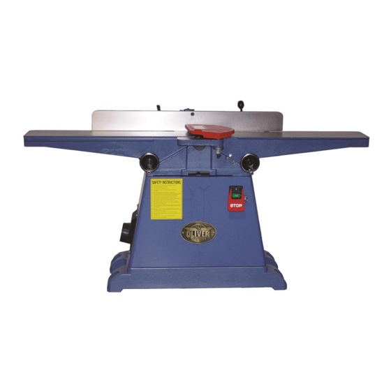
- Page 1 6” Jointer with Helical Cutterhead Owner’s Manual Oliver Machinery M-4220 09/2015 Copyright 2003-2015 Seattle, WA info@olivermachinery.net www.olivermachinery.net...
- Page 2 In no event shall Oliver be liable for death, personal or property injury, or damages arising from the use of its products.
-
Page 3: Table Of Contents
Page Table of contents SAFETY INSTRUCTIONS ...................... 2 Receiving Jointer ........................4 Unpacking and cleaning......................4 Using a sling ........................... 4 Placement the 6” jointer ......................4 Installation Blade Guard & Removal ..................5 Safety Switch .......................... 5 Grounding Instructions ......................6 Adjustments .......................... -
Page 4: Safety Instructions
SAFETY INSTRUCTIONS For Your Safety Read Instruction Manual Before Operating Jointer As with all machines, there is a certain amount of hazard involved with the use of this jointer. Use the machine with the respect and caution demanded where safety precautions are concerned. When normal safety precautions are overlooked or ignored, personal injury to the operator can result. - Page 5 Reduce the risk of unintentional starting. Make sure switch is in off position before plugging in. Use recommended accessories. Consult the owner’s manual for recommended accessories. The use of improper accessories may cause risk of injury to persons. Never stand on tool. Serious injury could occur if the tool is tipped or if the cutting tool is unintentionally contacted.
-
Page 6: Receiving Jointer
Receiving Jointer Upon delivery, open shipping containers and check that all parts are in good condition. Any damage should be reported to your distributor and shipping agent immediately. Before proceeding further, read your manual and familiarize yourself thoroughly with assembly, maintenance and safety procedures. -
Page 7: Installation Blade Guard & Removal
Installation Blade Guard & Removal Safety Switch WARNING: Use the jointer guard for all The jointer is equipped with a push-button switch operations. Do not connect the plug to power that will accept a safety padlock (not included). See Fig.10. To safeguard your machine from source unauthorized operation and accidental starting by 1. -
Page 8: Grounding Instructions
outlet that looks like the one illustrated in Sketch D Grounding Instructions Fig. 1. The tool has a grounding plug that looks like the plug illustrated in Sketch D. WARNING: If the machine does not come Make sure the tool is connected to an outlet having the !... -
Page 9: Adjustments
Adjustments Warning: Always disconnect the machine from the power source before making any OUTFEED INFEED adjustments. TABLE (LEFT) TABLE Failure to heed this warning can lead to serious (RIGHT) personal injury. Note: Clockwise raises the table, counterclockwise lowers the table. To adjust outfeed table Fig. - Page 10 Depth of Cut Depth of cut is determined by the height of the infeed table relative to the high point of the knives on the cutterhead. When facing the width of a board (as opposed to the edge of a board), NEVER attempt to take off more than 1/64"...
-
Page 11: Fence Adjustments: Tilt
Table Gibs and Leveling The table gibs on your machine are factory adjusted and may never require readjustment. Should any adjustment become necessary, do the following: 1. Lightly loosen the 2 wing screw (A), Fig. 7. By loosening 7 lock nuts (B) then tighten 7 Set screws (C) , should be loose enough to move the table. - Page 12 Fence Stop Adjustments Periodically check the 90° and 45° backward (135°) tilt accuracy of the fence with an angle measuring device, such as an adjustable square or machinist’s protractor. 90º Fence Adjustment Referring to Fig. 9: The 90º stop is controlled by the stop bolt (A) and the stop plate (B).
-
Page 13: Helical Cutterhead
Cutterhead Removal Helical Cutterhead If removal of the cutterhead is necessary, do the following: Knife inserts are dangerously sharp. WARNING: Use extreme caution when inspecting, WARNING: Disconnect jointer from removing or replacing knife inserts. ! power source. The knife inserts on the Jointer are four-sided. 1. -
Page 14: Replacement
Replacement Jointing Knives After extended use it will be necessary to sharpen the knives on the cutterhead assembly so that all knives protrude exactly the same height above the cutterhead . To joint the knives: WARNING: Disconnect machine from power source. Use approved eye !... -
Page 15: Replacement The Belts
Replacement the Belts FIG. 18 After extended use it will be necessary to adjustment or change the belts on the jointer, do the following: WARNING: Disconnect machine from power source. Use approved eye ! protection whenever sharpening blades. 1. Remove the pulley cover & cover on the rear stand , Fig 18. -
Page 16: Basic Operations
two handed push Basic Operations block Before making any cuts on the stock, make a few practice cuts by raising the infeed table to “ 0" and with the power disconnected. In this manner you will acquaint yourself with the feel of jointer operations. - Page 17 Surfacing: Long Boards left hand pushes down toward fence The use of push blocks will help to insure as right hand against hands coming in contact with cutterhead starts feed in the event of a kickback and as trailing end of board passes over cutterhead.
- Page 18 Jointing (or Edging) Never edge a board that is less than 3 inches move fence forward wide, less than 1/4 inch thick, or 12 inches to expose only amount of cutterhead required long, without using a push block. CAUTION: When workpiece is twice the è...
-
Page 19: Push Blocks
Skewing (Shear Cutting) When edging or facing burl or birds-eye maple, it is not unusual to deface or mar the surface being finished. This is caused by the cutterhead blades at times cutting against the grain. In order to prevent the defacing or marring of this type wood, it is necessary to skew, or angle finish, the material being worked. -
Page 20: Wiring Diagrams
Wiring Diagrams... -
Page 21: Parts Diagrams
Parts Diagrams... -
Page 24: Parts List
Parts List Part No. Descriptions Q'ty 230035-000 LOCK HANDLE 006001-091 FLAT WASHER 13*28*3.0t 130019-903 PLATE STOP 050093-000 CLAMP 250034-615 KNOB FENCE TILT 360038-901 HANDLE SHAFT 360074-901 CRANK 003103-102 CAP SCREW 1/4"-20NC*1/2" 360075-901 CLAMP SCREW 172285-905 FLAT WASHER 13*35*5.0t 009011-100 HEX. NUT 1/2"-12NC 360078-000 003103-104... - Page 25 Part No. Descriptions Q'ty 003006-302 HEX. SCREW 3/8"-24NF*119mm 230053-000 SCREW WING 920155-000 CUTTERHEAD GUARD ASS'Y 922909-000 TABLE ASS'Y 003202-104 SET SCREW 5/16"-18NC*1" 381094-901 FIXED PLATE 003104-104 CAP SCREW 5/16"-18NC*1" 360989-901 PLUNGER 381023-901 HOUSING PLUNGER 280010-000 SPRING 230156-615 KNOB PLUNGER 011001-106 SPRING PIN 3*20 230009-000...
- Page 26 Part No. Descriptions Q'ty 453011-013 POWER CORD SJT14AWG*3C*2400mm 020004-000 STRAIN RELIEF SB8R-1 900808-000 MOTOR ASSEMBLY 1.5HP*110/220V*60HZ*1PH 79.1 603077-000 MOTOR 1.5HP*110/220V*60HZ*1PH 79.2 012003-010 5*5*30 79.3 050021-901 MOTOR PULLEY 79.4 003201-102 SET SCREW 1/4"-20NC*3/8" 79.5 473003-006 MOTOR CORD SJT14AWG*3C*750mm 003003-203 HEX. SCREW 5/16"-18NC*3/4"...
Need help?
Do you have a question about the 4220 and is the answer not in the manual?
Questions and answers