Table of Contents
Advertisement
Quick Links
Advertisement
Table of Contents
Troubleshooting

Related Manuals for DeDietrich EASYLIFE Alezio G AWHP 4.5MR–EMC 24/28 MI HYBRIDE


Summary of Contents for DeDietrich EASYLIFE Alezio G AWHP 4.5MR–EMC 24/28 MI HYBRIDE
- Page 1 EASYLIFE User Guide Hybrid heat pump Alezio G hybrid AWHP 4.5MR–EMC 24/28 MI HYBRIDE AWHP 4.5MR–EMC 34/39 MI HYBRIDE AWHP 6MR–EMC 24/28 MI HYBRIDE AWHP 6MR–EMC 34/39 MI HYBRIDE AWHP 8MR–EMC 24/28 MI HYBRIDE AWHP 8MR–EMC 34/39 MI HYBRIDE S U S T A I N A B L E C O M F O R T ®...
- Page 2 Dear Customer, Thank you very much for buying this appliance. Please read through the manual carefully before using the product, and keep it in a safe place for later reference. In order to ensure continued safe and efficient operation we recommend that the product is serviced regularly. Our service and customer service organisation can assist with this.
-
Page 3: Table Of Contents
Contents Contents Safety ................... . 5 General safety instructions . - Page 4 Contents Setting the parameters ............... . . 38 6.4.1 Setting the room temperature set point in comfort mode .
-
Page 5: Safety
1 Safety Safety General safety instructions Danger This appliance can be used by children aged from 8 years and above and persons with reduced physical, sensory or mental capabilities or lack of experience and knowledge if they have been given supervision or instruction concerning use of the appliance in a safe way and understand the hazards involved. - Page 6 1 Safety Caution Installation of the heat pump must be done by a qualified professional in accordance with prevailing local and national regulations. Warning Do not touch the refrigeration connection pipes with your bare hands while the heat pump is running.
- Page 7 1 Safety Caution The system must satisfy each point in the rules (DTU, EN and others, etc.) that govern works and interventions in individual homes, blocks of flats or other buildings. Important Heating water and domestic water must not come into contact with each other.
-
Page 8: Recommendations
1 Safety Recommendations Caution Install the hydraulic module and the boiler for the hybrid system in a location protected from freezing. Caution If the home is unoccupied for a long period and there is a risk of frost, drain the hybrid system. Important Keep the hybrid system accessible at all times. -
Page 9: Specific Safety Instructions
1 Safety Important Keep this document close to the place where the appliance is installed. Caution Do not make any modifications to the hybrid system without the written consent of the manufacturer. Warning In accordance with the NFC 15.100 electrical safety standard, only qualified professionals are permitted access to the inside of the appliance. - Page 10 1 Safety The vapours are heavier than air and may lead to asphyxia owing to reduced oxygen levels. Liquefied gas: contact with the liquid may cause serious frost burn and eye injuries. Product classification: this product is not classified as a "hazardous preparation"...
- Page 11 1 Safety Tab.2 Precautions for use First aid If inhaled: Evacuate the subject from the contaminated area and take him into the open air. If feeling unwell: call a doctor. In the event of contact with the skin: Treat frost injuries like burns. Rinse with copious amounts of tepid water, do not remove clothing (risk of adhesion to the skin).
-
Page 12: Liabilities
1 Safety Personal protection Respiratory protection: If ventilation is insufficient: AX type cartridge mask. In confined spaces: self-contained breathing apparatus. Hand protection: protective gloves in leather or nitrile rubber. Eye protection: safety glasses with side protection. Skin protection: clothing made principally of cotton Industrial hygiene: do not drink, eat or smoke at the place of work. -
Page 13: Manufacturer's Liability
1 Safety If maintenance is necessary, warn the user of the obligation to check the appliance and keep it in good working order. Give all the instruction manuals to the user. 1.4.3 Manufacturer's liability Our products are manufactured in compliance with the requirements of the various Directives applicable. -
Page 14: About This Manual
2 About this manual About this manual General This manual is intended for the user of a Alezio G hybrid hybrid heat pump. Additional documentation These instructions contain information on the indoor module for the hybrid heat pump (hydraulic module + boiler), and some information on the outdoor unit. -
Page 15: Technical Specifications
3 Technical specifications Technical specifications Homologations 3.1.1 Directives This product has been manufactured and put into circulation in accordance with the requirements and standards of the following European Directives: Gas Appliances Regulation (EU) (2016/426) Pressure Equipment Directive 2014/68/EU Electromagnetic Compatibility Directive (2014/30/EU). Low Voltage Directive (2014/35/EU). -
Page 16: Factory Test
3 Technical specifications Country Category Gas type Connection pressure (mbar) Spain G20 (H gas) 2H3B/P G30/G31 (butane/propane) 30-50 Finland G20 (H gas) 2H3B/P G30/G31 (butane/propane) France G20 (H gas) 2Esi3B/P G25 (L gas) G30/G31 (butane/propane) 30-50 Greece G20 (H gas) 2H3B/P G30/G31 (butane/propane) 30-50... -
Page 17: Technical Data
3 Technical specifications Technical data 3.2.1 Boiler specifications Tab.5 General Alezio G hybrid 24/28 MI 34/39 MI Nominal heat output (Pn) min–max 5.5 - 23.8 7.7 - 34.7 Central heating operation (80 °C/60 °C) 19.8 29.8 Nominal heat output (Pn) min–max 5.5 - 27.5 7.7 - 37.8... -
Page 18: Heat Pump
3 Technical specifications Tab.10 Other data Alezio G hybrid 24/28 MI 34/39 MI Boiler weight (empty) 28.5 Average acoustic level at a distance of one metre Central heating dB(A) from the boiler operation DHW operation (1) Maximum 3.2.2 Heat pump Maximum operating pressure: 0.3 MPa (3 bar) Tab.11 Conditions of use... -
Page 19: Weight
3 Technical specifications Tab.14 Cooling mode: outside air temperature +35 °C, water temperature at the outlet +18 °C. Performances in accordance with EN 14511-2. Measurement type Unit AWHP 4.5 MR AWHP 6 MR-3 AWHP 8 MR-2 Cooling output 3.80 4.69 7.90 Energy efficiency ratio 4.28... -
Page 20: Technical Data - Low-Temperature Heat Pump Combination Heaters
3 Technical specifications Tab.17 Outdoor unit Weight (empty) Unit AWHP 4.5 MR AWHP 6 MR-3 AWHP 8 MR-2 Outdoor unit 3.2.4 Technical data - Low-temperature heat pump combination heaters Tab.18 Technical parameters for heat pump combination heaters (parameters declared for medium-temperature application) Product name AWHP 4.5MR–... -
Page 21: Hydraulic Module Circulating Pump
3 Technical specifications Product name AWHP 4.5MR– AWHP 6MR3– AWHP 8MR– EMC 24/28 MI EMC 24/28 MI EMC 24/28 MI HYBRIDE HYBRIDE HYBRIDE = bivalent temperature COPd 3.46 3.40 3.49 COPd = operation limit temperature 1.84 1.52 1.63 Operation limit temperature for air-to-water °C heat pumps WTOL... -
Page 22: Description Of The Product
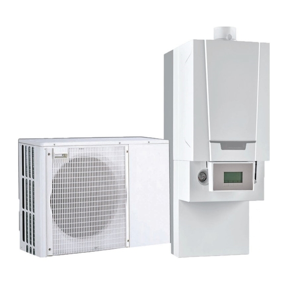
4 Description of the product Description of the product General description The hybrid heat pump comprises: an indoor module for controlling the heating circuit water a reversible outdoor unit for the production of energy in heating mode and in cooling mode. The indoor module comprises: a hydraulic module, which integrates the functions for the heat pump's indoor module... -
Page 23: Main Components
4 Description of the product Fig.3 General operating principle MW-5000395-1 1 Evaporator (fin battery in the outdoor unit) 5 Electrical energy 2 Compressor 6 Heating water 3 Condenser (plate exchanger in the indoor module) 7 Energy flow 4 Electronic expansion valve 8 Heat recovered from the environment Main components 4.3.1... -
Page 24: Main Components Of The Hydraulic Module
4 Description of the product 4.3.2 Main components of the hydraulic module Fig.5 Main components of the hydraulic 1 Automatic air vent module 2 Low-loss header 3 Electronic pressure gauge 4 Return from boiler back-up 5 Domestic hot water outlet (coming from the boiler) 6 Gas inlet (to the boiler) 7 Flow meter 8 EHC–04 PCB for controlling the heat pump hybrid system... -
Page 25: Description Of The Display
4 Description of the product 4.4.2 Description of the display Hydraulic back-up Fig.7 Hydraulic back-up in demand Electrical back-up Fig.8 Stage 1 of the electrical back-up Stage 2 of the electrical back-up Status of the Compressor Fig.9 Steady symbol: compressing running Operating modes Fig.10 Steady symbol: heating function enabled... - Page 26 4 Description of the product Menu display Fig.13 Information menu: displays the measured values and the statuses of the appliance User menu: provides access to the User level setting parameters Installer menu: provides access to the Installer level setting parameters Manual Forcing menu: the appliance runs at the set point displayed, the pumps operate and the three-way valves are not controlled.
- Page 27 4 Description of the product Temperature sensors Fig.18 Room temperature sensor connected: fixed symbol for WINTER mode, flashing symbol for SUMMER mode. Outside temperature sensor connected: fixed symbol for WINTER mode, flashing symbol for SUMMER mode. Other Information Fig.19 Test Menu: forced operation in heating and cooling mode Three-way valve connected Three-way valve closed Three-way valve open...
-
Page 28: Operation
5 Operation Operation Use of the control panel 5.1.1 Browsing in the menus Press any key to turn on the backlight for the control panel screen. If no key is pressed within 3 minutes, the control panel backlight will go out. -
Page 29: Shutdown
5 Operation Shutdown 5.3.1 Switching off the heating Important Heating mode can be managed via the TIME PROG sub-menu dedicated to timer programming. Important If the heating function is shut off, then the cooling will also be shut off. Fig.24 1. -
Page 30: Stopping Domestic Hot Water Production
5 Operation 5.3.2 Stopping domestic hot water production Important Domestic hot water production can be managed via the TIME PROG sub-menu dedicated to timer programming. Fig.27 1. Go to stop mode by pressing the key. MW-5000135-3 Fig.28 2. Select domestic hot water production mode pressing the key. - Page 31 5 Operation If the water temperature is lower than 5°C, the circulating pump starts If the water temperature is lower than 3°C, the back-up starts up. If the water temperature is higher than 10°C, the back-up shuts down and the circulating pump continues to run for a short time. The radiator valves in rooms where there is a risk of frost must be fully open.
-
Page 32: Settings
6 Settings Settings Modifying the User parameters Caution Altering the factory settings may impair operation of the appliance. Fig.30 1. Go to the User menu. 2. Select the desired sub-menu by pressing the key. 3. Confirm the selection by pressing the key. - Page 33 6 Settings Parameter Description Factory setting Factory setting CIRCA CIRCB CP082 Room setpoint temperature of the user zone activity in activity zone Can be set from 5 °C to 30 °C CP083 Room setpoint temperature of the user zone activity in activity zone Can be set from 5 °C to 30 °C CP084 Room setpoint temperature of the user zone activity in activity zone...
-
Page 34: User \Dhw Menu
6 Settings Parameter Description Factory setting Factory setting CIRCA CIRCB CP570 Time Program of the zone selected by the user 0 = programme 1 1 = programme 2 2 = programme 3 CP660 Choice icon to display this zone 0 =None 1 =All 2 =Bedroom 3 =Livingroom... -
Page 35: User \Hmi Menu
6 Settings Parameter Description Factory setting AP073 Outdoor temperature: upper limit for heating SUMMER / WINTER set point switch: Can be set from 15 °C to 30.5 °C AP074 The heating is stopped. Hot water is maintained. Force Summer Mode SUMMER override: 0 = off 1 = on... -
Page 36: Counters /Time Prog / Clock Menus
6 Settings Tab.26 Parameter Description Factory setting EHC–04 HP062 Hybrid electricity cost in high tarif 0.13 €/kWh Can be set from 0.01 to 2.50 €/kWh HP063 Hybrid electricity cost in low tarif 0.09 €/kWh Can be set from 0.01 to 2.50 €/kWh HP064 Cost of fossil energy (oil or gas) - price per litre or per m3 0.90 €/kWh... -
Page 37: Counters, Time Prog, Clock \Circa, Circb And Dhw Menus
6 Settings Parameter Description Unit EHC–04 SCB-04 DC003 Number of hours during which the diverting valve hours is in DHW position DC004 Number of compressor start-ups during domestic hot water production DC005 Number of compressor start-ups PC003 Number of compressor operating hours hours CODE Enter the installer code to access the following pa... -
Page 38: Setting The Parameters
6 Settings Setting the parameters 6.4.1 Setting the room temperature set point in comfort mode Important The room temperature set point can be managed via the TIME PROG sub-menu dedicated to timer programming. Important To set the room set point temperature in reduced mode, it is necessary to set the CP080 parameter available in the User menu. -
Page 39: Activating Manual Forcing For Heating
6 Settings Important The heat pump switches to cooling automatically when the outdoor temperature is +2 °C greater than the summer/winter switching set point temperature (22 °C). The forced cooling function is used to have cooling regardless of the outdoor temperature. -
Page 40: Setting The Timer Programming
6 Settings Fig.41 2. Set the value of the heating water temperature set point by pressing key. 3. Confirm the new value of the heating water temperature set point by pressing the key. 4. Go back to the main display by pressing the key. - Page 41 6 Settings Fig.46 7. Set the start time for the period by pressing the key. 8. Confirm the selection by pressing the key. MW-5000142-2 Fig.47 9. Select the status that corresponds to the period by pressing key. Status for periods Description comfort mode reduced mode...
-
Page 42: Reading Out Measured Values
7 Reading out measured values Reading out measured values The measured values are available in the Information menu of the different PCBs. Certain parameters are displayed: according to certain system configurations, according to the options, circuits or sensors actually connected. Tab.32 Choosing the menu Counters... -
Page 43: Reading Out Hybrid Measured Values
7 Reading out measured values Parameter Description Unit EHC–04 SCB-04 DM001 Domestic Hot Water tank temperature (bottom sensor) °C DM006 Domestic Hot Water tank temperature (top sensor) DM009 Automatic/derogation status of Domestic Hot Water °C mode: 0 =Scheduling 1 = Manual 2 =Antifrost 3 =Temporary DM029... -
Page 44: Control System Sequence
7 Reading out measured values Control system sequence Tab.36 List of statuses and sub-statuses Status Appliance: AM012 parameter Appliance sub status: AM014 parameter 00= total system shut-down 1= heating / cooling / domestic hot water de Heat Demand mand 00 = off The set point is reached. - Page 45 7 Reading out measured values Status Appliance: AM012 parameter Appliance sub status: AM014 parameter 4= operating in domestic hot water mode 30= normal operation The compressor or the back-ups are running. 31= internal set point limited If the heating set point on the heat pump differs from the system set point. 60= pump post-operation Heat pump and back-up shut-down, system pump operation.
- Page 46 7 Reading out measured values Status Appliance: AM012 parameter Appliance sub status: AM014 parameter 8= controlled compressor shut-down Controlled Stop 00= off: the heating or cooling set point has been reached 01= anti-short cycle The heating set point has been reached. The compressor is not authorised to restart.
- Page 47 7 Reading out measured values Status Appliance: AM012 parameter Appliance sub status: AM014 parameter Load test CH max 30= normal operation. The compressor or the back-ups are running. 31= internal set point limited If the heating set point on the heat pump differs from the system set point. 60= pump post-operation Heat pump and back-up shut-down, system pump post-operation.
- Page 48 7 Reading out measured values Status Appliance: AM012 parameter Appliance sub status: AM014 parameter Frost protection 30= normal operation The compressor or the back-ups are running. 31= internal set point limited If the heating set point on the heat pump differs from the system set point. 60= pump post-operation Heat pump and back-up shut-down, system pump post-operation.
-
Page 49: Maintenance
8 Maintenance Maintenance General Maintenance operations are important for the following reasons: To guarantee optimum performance. To extend the life of the equipment. To provide an installation which offers the user optimum comfort over time. Caution Only qualified professionals are authorised to carry out maintenance work on the heat pump and the heating system. -
Page 50: Checking The Water Pressure
8 Maintenance 8.2.1 Checking the water pressure 1. Check the water pressure. The water pressure must be at least 0.8 bar. 2. If the water pressure is lower than 0.8 bar, top up the central heating system. Cleaning the casing 1. -
Page 51: Troubleshooting
9 Troubleshooting Troubleshooting Error codes 9.1.1 Error codes An error code is a temporary status, resulting from the detection of a heat pump anomaly. The control panel attempts automatic restart of the heat pump until it switches on. When one of the following codes is displayed and the heat pump cannot restart automatically, contact a maintenance technician. -
Page 52: Fault Codes
9 Troubleshooting Error Message Description code H02.36 Funct device lost Functional device has been disconnected No communication between the central unit PCB and the additional circuit PCB H02.37 Uncritic device lost Uncritical device has been disconnected No communication between the central unit PCB and the additional circuit PCB H02.60 Unsupported function The zone doesn't support the selected function... -
Page 53: Blocking Of The Boiler
9 Troubleshooting 9.1.4 Blocking of the boiler A (temporary) blocking mode is a boiler status, resulting from an abnormal state. The blocking code for the boiler is accessed via the parameter HM042 in the Information menu. Important The boiler automatically returns to operation once the cause of the blocking has been removed. -
Page 54: Accessing The Error Memory
9 Troubleshooting Error code Description Flow temperature sensor open Temperature of heat exchanger too low Temperature of heat exchanger too high Return temperature sensor short-circuited Open circuit in return temperature sensor Return temperature too low Return temperature too high Difference between the flow and return temperatures too high Heat exchanger temperature outside of the normal range (STB safety thermostat) Five failed burner starts False flame signal... -
Page 55: Fault Finding
9 Troubleshooting Fig.52 6. Go back to the Er:xxx display by pressing the key. Press the key: the CLR parameter flashes after the errors. 000 corresponds to the PCB selected. Clear the error memory by pressing the key. 7. Exit the Malfunctions menu by pressing the key. - Page 56 9 Troubleshooting Problems Probable causes Corrections Clicking in the central The central heating pipe Slightly loosen the clamps. heating pipes clamps are too tight. There is air in the heating Vent any air in the domestic hot water tank, the pipes and the taps to pipes.
-
Page 57: 10 Decommissioning And Disposal
10 Decommissioning and disposal 10 Decommissioning and disposal 10.1 Decommissioning procedure To decommission the heat pump temporarily or permanently: 1. Contact the installer. 10.2 Disposal and recycling Fig.53 Warning Removal and disposal of the heat pump must be carried out by a qualified professional in accordance with prevailing local and national regulations. -
Page 58: 11 Environmental
11 Environmental 11 Environmental 11.1 Energy savings Energy-saving advice: Do not block ventilation outlets. Do not cover the radiators. Do not hang curtains in front of the radiators. Install reflective panels behind the radiators to prevent heat losses. Insulate the pipes in rooms that are not heated (cellars and lofts). Close the radiators in rooms not in use. -
Page 59: Appendix
12 Appendix 12 Appendix 12.1 Product fiche Tab.42 Product sheet for heat pump combination heaters AWHP AWHP 6MR– AWHP 8MR– 4.5MR–EMC EMC 24/28 MI EMC 24/28 MI 24/28 MI HYBRIDE HYBRIDE HYBRIDE / AWHP 6MR3–EMC 24/28 MI HYBRIDE Space heating - Temperature application Water heating - Declared load profile Seasonal space heating energy efficiency class under average climate conditions... -
Page 60: Package Fiche
12 Appendix 12.3 Package fiche Important ‘Medium-temperature application’ means an application where the heat pump space heater or heat pump combination heater delivers its declared capacity for heating at an indoor heat exchanger outlet temperature of 55 °C. Fig.54 Package fiche for medium-temperature heat pumps indicating the space heating energy efficiency of the package Seasonal space heating energy effi... - Page 61 12 Appendix The value of the mathematical expression 115/(11 · Prated), whereby "Prated" is related to the preferential space heater. The value of the difference between the seasonal space heating energy efficiencies under average and colder climate conditions, expressed in %. The value of the difference between the seasonal space heating energy efficiencies under warmer and average climate conditions, expressed in %.
- Page 62 12 Appendix 7611444 - v06 - 04032019...
- Page 63 © Copyright All technical and technological information contained in these technical instructions, as well as any drawings and technical descriptions supplied, remain our property and shall not be multiplied without our prior consent in writing. Subject to alterations.
- Page 64 57, rue de la Gare - F-67580 Mertzwiller SERVICE CONSOMMATEURS 03 88 80 27 00 0,15 € / min 0 825 120 520 03 88 80 27 99 www.dedietrich-thermique.fr 000 «БДP T » VAN MARCKE 129164, Россия, г. Москва Weggevoerdenlaan 5 Зубарев...
Need help?
Do you have a question about the EASYLIFE Alezio G AWHP 4.5MR–EMC 24/28 MI HYBRIDE and is the answer not in the manual?
Questions and answers