
Subscribe to Our Youtube Channel
Related Manuals for DeDietrich AWHP 4 MR


Summary of Contents for DeDietrich AWHP 4 MR
-
Page 1: User Manual
Ireland User Manual Reversible air / water "Split Inverter" heat pump Single unit Alezio MIV-4/E 4–8 V200 MIV-4/E 11–16 V200 MIV-4/H 4–8 V200 MIV-4/H 11–16 V200... - Page 2 Dear customer, Thank you for purchasing this appliance. Please read this manual carefully before using the product and keep it in a safe place for future reference. In order to ensure continued safe and efficient operation we recommend that the product is regularly maintained. Our Service and After Sales organization can assist with this.
-
Page 3: Table Of Contents
Contents Contents 1 Safety ................5 1.1 General safety instructions . - Page 4 Contents Troubleshooting ................43 General .
-
Page 5: Safety
1 Safety 1 Safety 1.1 General safety instructions Danger This appliance can be used by children aged 8 years and above and by persons with reduced physical, sensory or mental capabilities or lack of experience and knowledge when they have been given supervi sion or instruction concerning the safe use of the de... - Page 6 1 Safety Caution The system must satisfy each point in the rules in force in the country that govern works and interven tions in individual homes, blocks of flats or other build ings. Note Heating water and domestic water must not come into contact with each other.
- Page 7 1 Safety Note Setting the domestic hot water temperature set point: refer to the chapter "Setting the domestic hot water temperature set point". Caution Pressure limiter device: refer to the chapter Special precautions to be taken when connecting the domes tic hot water circuit (Installation and Service Manual).
-
Page 8: Recommendations
1 Safety Caution This appliance must be connected to the protective earth. Earthing must comply with prevailing installation standards. Earth the appliance before making any electrical con nections. Type and calibre of the protective equipment: refer to the chapter Recommended cable cross-sections (In stallation and Service Manual). - Page 9 1 Safety Note The frost protection function does not work if the heat pump is switched off. Caution If the home is unoccupied for a long period and there is a risk of frost, drain the indoor module and the heat ing system.
-
Page 10: Specific Safety Instructions
1 Safety 1.3 Specific safety instructions Warning Refrigerant fluid and pipes: Use only R410A refrigerant fluid to fill the installa tion. Use tools and pipe components especially designed for use with R410A refrigerant fluid. Use copper pipes deoxidised with phosphorus to carry the refrigerant fluid. - Page 11 1 Safety Tab.2 Precautions for use First aid If inhaled: Evacuate the subject from the contaminated area and take him into the open air. If feeling unwell: call a doctor. In the event of contact with the skin: Treat frost injuries like burns. Rinse with copious amounts of tepid water, do not remove clothing (risk of adhesion to the skin).
-
Page 12: Liabilities
1 Safety Considerations on dis Note posal Disposal must be done in compliance with prevailing local and national regulations. Product waste: consult the manufacturer or the supplier for information on recovery or recycling. Soiled packaging: reuse or recycle after decontamination. Destroy in au thorised installations. - Page 13 1 Safety Have the required inspections and maintenance carried out by a qualified installer. Keep the instruction manuals in good condition close to the appliance. 7623755 - v02 - 03072015 MIV-4...
-
Page 14: About This Manual
2 About this manual About this manual General This manual is intended for the user of a MIV-4 heat pump. This manual can also be found on our internet site. Symbols used 2.2.1 Symbols used in the manual This manual uses various danger levels to draw attention to special in structions. - Page 15 2 About this manual Fig.3 Symbols used on the connection la 1 Sensor cable - low voltage 2 Power cord 230 V 3 Heating circuit flow 4 Circuit B flow 5 Heating circuit return 6 Circuit B return (optional) G1" 7 Connection for recirculation G1"...
-
Page 16: Technical Specifications
Conditions of use Water (°C) Outside air (°C) Limit operating temperatures in heating +18 / +60 AWHP 4 MR, AWHP 6 MR-2 : -15 / +35 mode Other models: -20 / +35 Limit operating temperatures in cooling +7 / +25... - Page 17 3 Technical specifications Measure Unit AWHP 4 AWHP 6 AWHP 8 AWHP 11 AWHP 11 AWHP 16 AWHP 16 ment type MR-2 MR-2 MR-2 TR-2 MR-2 TR-2 Coefficient 3.32 2.97 3.46 3.20 3.20 3.27 3.27 of perform ance (COP) Absorbed 1.13 1.08 1.53...
-
Page 18: Domestic Hot Water Tank
°C Maximum operating pressure MPa (bar) 1.0 (10.0) Water capacity Litres Tab.10 Common specifications AWHP/AWHP-V220 AWHP 4 MR AWHP 6 MR-2 AWHP 8 MR-2 AWHP 11 MR-2 AWHP 16 MR-2 AWHP 11 TR-2 AWHP 16 TR-2 1 hour 54 minutes... -
Page 19: Combination Heaters With Medium-Temperature Heat Pump
3.2.4 Combination heaters with medium-temperature heat pump Tab.13 Technical parameters for heat pump combination heaters (parameters declared for medium-temperature application) Product name MIV-4 MIV-4 MIV-4 AWHP 4 MR AWHP 6 MR-2 AWHP 8 MR-2 Air-to-water heat pump Water-to-water heat pump Brine-to-water heat pump... - Page 20 3 Technical specifications Product name MIV-4 MIV-4 MIV-4 AWHP 4 MR AWHP 6 MR-2 AWHP 8 MR-2 Supplementary heater Psup Rated heat output (24) Type of energy input Electricity Electricity Electricity Other characteristics Capacity control Variable Variable Variable Sound power level, indoors - outdoors 53 –...
- Page 21 3 Technical specifications Product name MIV-4 MIV-4 AWHP 11 MR-2 AWHP 16 MR-2 ƞ Seasonal space heating energy efficiency under average conditions ƞ Seasonal space heating energy efficiency under colder conditions Seasonal space heating energy efficiency under ƞ warmer conditions Declared coefficient of performance or primary en...
-
Page 22: Circulating Pump
3 Technical specifications The back cover for contact details. 3.2.5 Circulating pump Note The benchmark for the most efficient circulating pumps is EEI ≤ 0.20. MIV-4 7623755 - v02 - 03072015... -
Page 23: Description Of The Product
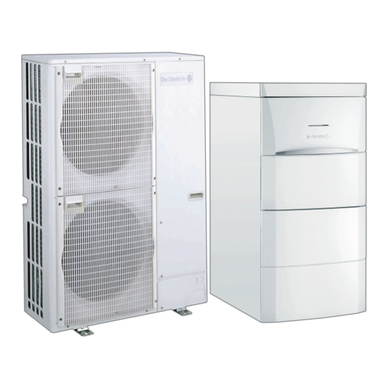
4 Description of the product Description of the product General description The MIV-4 heat pump comprises: an indoor module, including a domestic hot water tank and a control panel. A reversible outdoor unit for energy production in heating or cooling mode. -
Page 24: Main Components
4 Description of the product Fig.4 General operating principle MW-6000391-1 1 Evaporator (fin battery in the outdoor unit) 5 Electrical energy 2 Compressor 6 Heating water 3 Condenser (plate exchanger in the indoor module) 7 Energy flow 4 Electronic expansion valve 8 Heat recovered from the environment Main components Fig.5... -
Page 25: Control Panel Description
4 Description of the product Control panel description 4.4.1 Description of the keys Fig.6 Control panel keys MW-1000043-4 1 ESC key ( ) or key or CONFIRM ( 2 Key for the heating temperatures 3 Key for the domestic hot water temperatures 4.4.2 Description of the display Key functions Fig.7... - Page 26 4 Description of the product Electrical back-up Fig.9 Electrical back-up Stage 1 of the electrical back-up Stage 2 of the electrical back-up MW-6000364-1 Status of the Compressor Fig.10 Status of the Compressor Steady symbol: compressing running Flashing symbol: compressor off and run request pending MW-5000012-1 Operating modes Fig.11...
- Page 27 4 Description of the product Menu display Fig.14 Menu display Information menu: displays the measured values and the statuses of the appliance User menu: provides access to the User level setting parameters Installer menu: provides access to the Installer level setting param eters Manual Forcing menu: the appliance runs at the set point dis...
-
Page 28: Operation
5 Operation Operation Use of the control panel 5.1.1 Browsing in the menus Note The first time a key is pressed, the backlit screen is switched on. The name of the PCB is displayed: check that it is actually the PCB on which the setting must be made. -
Page 29: Accessing The User Menu
5 Operation Fig.20 Confirming the menu or parameter 4. To confirm selection of the desired menu, sub-menu or parameter, press the key. Note If no keys are pressed for 3 minutes, the appliance returns to nor mal operating mode. The display disappears after a few seconds' inactivity. MW-5000019-3 Fig.21 Modifying a value... -
Page 30: Accessing The Hour Run Meters / Timer Program / Clock Sub-Menus
5 Operation 1. Access the menus by pressing the two keys on the right simultane ously. 2. Select the User menu by pressing the key until the icon flashes. Fig.24 Accessing the User menu 3. Press to access the User menu. Note The User menu is available only if the icon flashes. -
Page 31: Shutdown
5 Operation Shutdown 5.3.1 Switching off the heating Note The name of the PCB is displayed. Check that it is actually the PCB on which the setting must be made. Fig.28 Selecting the shut-down mode 1. Select the shut-down mode by pressing the key twice. -
Page 32: Stopping Domestic Hot Water Production
5 Operation 5.3.2 Stopping domestic hot water production Note The name of the PCB is displayed. Check that it is actually the PCB on which the setting must be made. Fig.31 Selecting the shut-down mode 1. Select the shut-down mode by pressing the key twice. -
Page 33: Frost Protection
5 Operation Fig.34 Cooling function 2. Select the AP015 cooling parameter by pressing the and confirm by pressing the key. 3. Select cooling function shut-down by pressing the key and con firm by pressing the key. 4. Go back to the main display by pressing the key. -
Page 34: Settings
6 Settings Settings List of parameters 6.1.1 Menu List Information menu User menu Installer menu Manual Forcing menu Failure menu Hour run meters sub-menu Timer Program sub-menu Clock sub-menu 6.1.2 Information Menu Certain parameters are displayed: according to certain system configurations, according to the options, circuits or sensors actually connected. - Page 35 6 Settings Parameters Description Factory setting Customer setting AP016 Central heating operation: 0 = OFF 1 = ON AP017 Domestic hot water tank operation: 0 = OFF 1 = ON AP073 SUMMER / WINTER set point switch: 22°C Can be set from 15 to 30 °C. Set to 30.5 °C = function deactivated AP074 SUMMER override:...
-
Page 36: Pcb Parameters For The Pcb + Sensor Kit For Circuits With Mixing Valve
6 Settings Parameters Description Factory setting Customer setting HP062 Cost of peak time electricity Can be set from 1 to 250 (x € 0.01/kWh) HP063 Cost of off-peak electricity Can be set from 1 to 250 (x € 0.01/kWh) HP064 Cost of fossil energy (oil or gas) - price per litre or per m Can be set from 1 to 250 (x €... - Page 37 6 Settings Sub-menu COUNTERS Tab.18 List of parameters Parameters Description Unit DC002 Number of reversal valve cycles DC003 Number of hours' reversal valve operation hours PC002 Number of burner start-ups in heating mode AC026 Number of hours' pump operation hours AC027 Number of pump start-ups AC005...
-
Page 38: Setting The Parameters
6 Settings Setting the parameters 6.2.1 Modifying the User parameters Note The name of the PCB is displayed. Check that it is actually the PCB on which the setting must be made. The parameters in the User menu can be modified by the user to meet his central heating and domestic hot water comfort requirements. -
Page 39: Setting The Heating
6 Settings 6.2.3 Setting the heating Note The name of the PCB is displayed. Check that it is actually the PCB on which the setting must be made. Fig.38 Accessing the heating parameters 1. Access the heating shut-down pressing the key twice. -
Page 40: Activating Manual Forcing
6 Settings Fig.41 Confirmation of the domestic hot wa 2. Display the domestic hot water production circuit parameters by ter circuit pressing the key. The name of the circuit and the domestic hot water temperature set point are displayed alternately. 3. -
Page 41: Setting The Timer Program
6 Settings 6.2.6 Setting the timer program Note The name of the PCB is displayed. Check that it is actually the PCB on which the setting must be made. Fig.45 Accessing the Hour Run Meters / 1. Access the Hour Run Meters / Timer Program / Clock menus. Timer Program / Clock menus 2. - Page 42 6 Settings Note key is used to move to the right. Note key is used to move to the left. Fig.49 Setting the time 5. Set the start time for the period S1 by pressing the key. Confirm by pressing the key.
-
Page 43: Maintenance
7 Maintenance Maintenance Troubleshooting Caution All work on the refrigeration circuit must be done by a qualified professional, according to prevailing codes of practice and safety in the profession (recovery of the refrigerant, brazing under nitro gen). All brazing work must be done by qualified welders. Caution This appliance is fitted with pressurised equipment, including the refrigeration pipes. -
Page 44: Cleaning The Casing
7 Maintenance Cleaning the casing 1. Clean the outside of the appliance using a damp cloth and a mild detergent. MIV-4 7623755 - v02 - 03072015... -
Page 45: Troubleshooting
8 Troubleshooting Troubleshooting Error messages Fig.51 Restarting the appliance 1. Press for 3 seconds to restart the appliance. MW-5000060-2 Fig.52 Error code display Note The previous codes are displayed alternately. In economy mode, the appliance will not run a domestic hot water heating cycle after a central heating cycle. - Page 46 8 Troubleshooting Code Message Description Check Internal error Contact the professional responsible for maintenance of the heat pump AWAITING The hybrid system has not Contact the professional responsible for maintenance of the heat pump CONFIGU been configured RATION NUMBER DHW T Bottom domestic hot water Contact the professional responsible for maintenance of the heat pump OPEN...
-
Page 47: Pcb Error Codes On The Pcb + Sensor Kit For Circuits With Mixing Valve
8 Troubleshooting Tab.23 List of errors Code Message Description Check LOCK- The BL input opened for a Contact the professional responsible for maintenance of the heat pump DOWN IN short period of time SYSTEM Heating water flow rate too Contact the professional responsible for maintenance of the heat pump FLOW LOCK- DOWN... -
Page 48: Error History
8 Troubleshooting Error history Fig.53 Accessing the menus 1. Access the menu level by pressing the two keys on the right simulta neously. MW-5000009-3 Fig.54 Accessing the Failure menu 2. Select the Failure menu by pressing the key. 3. Press the key to scroll through the error code history. - Page 49 8 Troubleshooting Problems Probable causes Corrections The heat pump does The heating set point tem Increase the value of parameter or, if a room thermostat is connec not work. perature is too low. ted, increase the temperature on it. The heat pump is not op Check that the heat pump is switched on.
-
Page 50: Decommissioning
9 Decommissioning Decommissioning Decommissioning procedure To decommission the heat pump temporarily or permanently: 1. Contact the installer. MIV-4 7623755 - v02 - 03072015... -
Page 51: Disposal
10 Disposal 10 Disposal 10.1 Disposal and Recycling Fig.55 Recycling Warning Removal and disposal of the heat pump must be carried out by a qualified professional in accordance with prevailing local and na tional regulations. MW-3000179-03 1. Switch off the heat pump. 2. -
Page 52: Environmental
11 Environmental 11 Environmental 11.1 Energy savings Tips on saving energy: Do not block ventilation outlets. Do not cover the radiators. Do not hang curtains in front of the radiators. Install reflective panels behind the radiators to prevent heat losses. Insulate the pipes in rooms that are not heated (cellars and lofts). -
Page 53: Warranty
12 Warranty 12 Warranty 12.1 General We would like to thank you for buying one of our appliances and for your trust in our product. In order to ensure continued safe and efficient operation we recommend that the product is regularly inspected and maintained. Your installer and our service department can assist with this. -
Page 54: Appendix
13 Appendix 13 Appendix 13.1 Product data sheet Tab.25 Product data sheet for heat pump combination heaters MIV-4 MIV-4 MIV-4 AWHP 4 MR AWHP 6 MR-2 AWHP 8 MR-2 Space heating - Temperature application Medium Medium Medium Water heating - Declared load profile... -
Page 55: Product Data Sheet - Temperature Controls
13 Appendix MIV-4 MIV-4 AWHP 11 MR-2 AWHP 16 MR-2 Water heating - Annual energy consumption under average climate con ditions Seasonal space heating energy efficiency under average climate condi tions Water heating energy efficiency under average climate conditions 106.00 106.00 Sound power level L indoors... - Page 56 13 Appendix Fig.56 Package fiche for medium-temperature heat pumps indicating the space heating energy efficiency of the package Seasonal space heating energy effi ciency of heat pump ‘I’ Temperature control Class I = 1%, Class II = 2%, Class III = 1.5%, Class IV = 2%, Class V = 3%, Class VI = 4%, from fi...
- Page 57 13 Appendix Tab.28 Weighting of medium temperature heat pumps II, package without hot water storage tank II, package with hot water storage tank Prated / (Prated + Psup) (1)(2) 1.00 1.00 0.70 0.63 0.45 0.30 0.25 0.15 0.15 0.06 0.05 0.02 0.02 ≥...
-
Page 58: Package Fiche - Combination Heaters (Boilers Or Heat Pumps)
13 Appendix 13.4 Package fiche - Combination heaters (boilers or heat pumps) Fig.57 Package fiche for combination heaters (boilers or heat pumps) indicating the water heating energy efficiency of the package Water heating energy effi ciency of combination heater ‘I’ Declared load profi... - Page 59 © Copyright All technical and technological information contained in these technical instructions, as well as any drawings and technical de scriptions supplied, remain our property and shall not be multiplied without our prior consent in writing. Subject to alterations.
- Page 60 Зубарев переулок, д. 15/1 +49 (0)25 72 / 9161-0 Бизнес-центр «Чайка Плаза», +49 (0)25 72 / 9161-102 офис 309 info@remeha.de +7 (495) 221-31-51 info@dedietrich.ru DE DIETRICH THERMIQUE Iberia S.L.U. DE DIETRICH SERVICE www.dedietrich-calefaccion.es www.dedietrich-heiztechnik.com Freecall 0800 / 201608 C/Salvador Espriu, 11 08908 L’HOSPITALET de LLOBREGAT...
Need help?
Do you have a question about the AWHP 4 MR and is the answer not in the manual?
Questions and answers