Table of Contents
Troubleshooting

Subscribe to Our Youtube Channel
Related Manuals for DeDietrich AWHP 4MR–EMC 24/28 MI HYBRIDE


Summary of Contents for DeDietrich AWHP 4MR–EMC 24/28 MI HYBRIDE
-
Page 1: User Manual
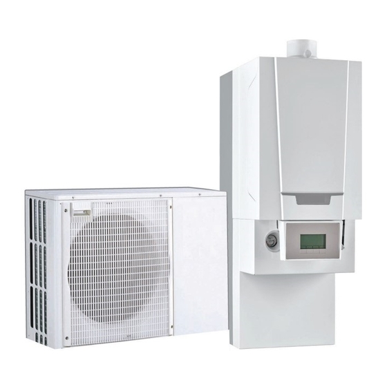
User Manual Hybrid heat pump Alezio G hybrid AWHP 4MR–EMC 24/28 MI HYBRIDE AWHP 4MR–EMC 34/39 MI HYBRIDE AWHP 6MR–EMC 24/28 MI HYBRIDE AWHP 6MR–EMC 34/39 MI HYBRIDE AWHP 8MR–EMC 24/28 MI HYBRIDE AWHP 8MR–EMC 34/39 MI HYBRIDE... - Page 2 Dear Customer, Thank you very much for buying this appliance. Please read through the manual carefully before using the product, and keep it in a safe place for later reference. In order to ensure continued safe and efficient operation we recommend that the product is serviced regularly. Our service and customer service organisation can assist with this.
-
Page 3: Table Of Contents
Contents Contents 1 Safety ................5 1.1 General safety instructions . - Page 4 Contents 6.2.3 Setting the room temperature set point in comfort mode ........39 6.2.4 Setting the domestic hot water temperature .
-
Page 5: Safety
1 Safety 1 Safety 1.1 General safety instructions Danger This appliance can be used by children aged from 8 years and above and persons with reduced physical, sensory or mental capabilities or lack of experience and knowledge if they have been given supervision or instruction concerning use of the appliance in a safe way and understand the hazards involved. - Page 6 1 Safety Warning Do not touch the refrigeration connection pipes with your bare hands while the heat pump is running. Dan ger of burn or frost injury. Warning Do not touch the radiators for long periods. Depending on the heat pump settings, the temperature of the ra diators may exceed 60°C.
-
Page 7: Recommendations
1 Safety Caution The system must satisfy each point in the rules in force in the country that govern works and interven tions in individual homes, blocks of flats or other build ings. Note Heating water and domestic water must not come into contact with each other. - Page 8 1 Safety Note Never remove or cover labels and data plates affixed to the appliances. Labels and data plates must be legible throughout the entire lifetime of the appliance. Immediately replace damaged or illegible instructions and warning stickers. Note Remove the casing only to perform maintenance and repair work.
-
Page 9: Specific Safety Instructions
1 Safety 1.3 Specific safety instructions Warning Refrigerant fluid and pipes: Use only R410A refrigerant fluid to fill the installa tion. Use tools and pipe components especially designed for use with R410A refrigerant fluid. Use copper pipes deoxidised with phosphorus to carry the refrigerant fluid. - Page 10 1 Safety Tab.2 Precautions for use First aid If inhaled: Evacuate the subject from the contaminated area and take him into the open air. If feeling unwell: call a doctor. In the event of contact with the skin: Treat frost injuries like burns. Rinse with copious amounts of tepid water, do not remove clothing (risk of adhesion to the skin).
-
Page 11: Liabilities
1 Safety Considerations on dis Note posal Disposal must be done in compliance with prevailing local and national regulations. Product waste: consult the manufacturer or the supplier for information on recovery or recycling. Soiled packaging: reuse or recycle after decontamination. Destroy in au thorised installations. - Page 12 1 Safety Failure to abide by the instructions on installing the appli ance. Failure to abide by the instructions on using the appliance. Faulty or insufficient maintenance of the appliance. 7611444 - v02 - 11122015...
-
Page 13: About This Manual
2 About this manual About this manual General This manual is intended for the user of a Alezio G hybrid hybrid heat pump. Additional documentation These instructions contain information on the indoor module for the hybrid heat pump (hydraulic module + boiler), and some information on the out door unit. -
Page 14: Technical Specifications
3 Technical specifications Technical specifications Homologations 3.1.1 Directives This product complies with the requirements of the following European Di rectives and Standards: Low Voltage Directive 2006/95/EC Generic standard: EN 60335–1 Relevant Standard: EN 60335-2-40 Electromagnetic Compatibility Directive 2004/108/EC Generic standards: EN 61000-6-3, EN 61000-6-1 Relevant Standard: EN 55014 Pressure Equipment Directive 97/23/EC, Article 3, paragraph 3 This product conforms to the requirements of European Directive... -
Page 15: Technical Data
3 Technical specifications Technical data 3.2.1 Boiler specifications Tab.5 General Alezio G hybrid Nominal output (Pn) min–max Central heating operation (80°C/60°C) Nominal output (Pn) min-max DHW operation (1) Factory setting Tab.6 Details of gas and flue gas Alezio G hybrid Central heating chimney efficiency (Hi) (80/60°C) at 20°C amb. -
Page 16: Heat Pump
3 Technical specifications 3.2.2 Heat pump Maximum operating pressure: 0.3 MPa (3 bar) Tab.11 Conditions of use Water (°C) Outside air (°C) Limit operating temperatures in heating +18 / +60 AWHP 4 MR, AWHP 6 MR-2 : -15 / +35 mode Other models: -20 / +35 Limit operating temperatures in cooling... -
Page 17: Weight
3 Technical specifications Measurement type Unit AWHP 4 MR AWHP 6 MR-2 AWHP 8 MR-2 Acoustic power - Out dB(A) 62.4 64.8 66.7 side Refrigerant fluid R410A Refrigerant connection inch 1/4 - 1/2 1/4 - 1/2 3/8 - 5/8 (Liquid - Gas) Max. - Page 18 3 Technical specifications Product name AWHP 4MR– AWHP 6MR– AWHP 8MR– EMC 24/28 MI EMC 24/28 MI EMC 24/28 MI HYBRIDE HYBRIDE HYBRIDE = operation limit temperature Bivalent temperature °C Degradation co-efficient — ƞ Seasonal space heating energy efficiency under average conditions ƞ...
-
Page 19: Hydraulic Module Circulating Pump
3 Technical specifications Product name AWHP 4MR– AWHP 6MR– AWHP 8MR– EMC 24/28 MI EMC 24/28 MI EMC 24/28 MI HYBRIDE HYBRIDE HYBRIDE Rated air flow rate, outdoors for air-to-water — 2100 2100 3300 heat pumps Declared load profile Daily electricity consumption 0.177 0.177 0.177... -
Page 20: Description Of The Product
4 Description of the product Description of the product General description The hybrid heat pump comprises: an indoor module for the production of heating circuit water a reversible outdoor unit for the production of energy in heating mode and in cooling mode. The indoor module comprises: a hydraulic module, which groups together the functions for the heat pump's indoor module... -
Page 21: Main Components
4 Description of the product Fig.3 General operating principle MW-5000395-1 1 Evaporator (fin battery in the outdoor unit) 5 Electrical energy 2 Compressor 6 Heating water 3 Condenser (plate exchanger in the indoor module) 7 Energy flow 4 Electronic expansion valve 8 Heat recovered from the environment Main components 4.3.1 Main boiler components... -
Page 22: Main Components Of The Hydraulic Module
4 Description of the product 4.3.2 Main components of the hydraulic module Fig.4 Main components of the hydraulic 1 Automatic air vent module 2 Low-loss header 3 Electronic pressure gauge 4 Return from boiler back-up 5 Domestic hot water outlet (coming from the boiler) 6 Gas inlet (to the boiler) 7 Flow meter 8 EHC-02 PCB for controlling the heat pump hybrid system... -
Page 23: Description Of The Display
4 Description of the product 4.4.2 Description of the display Key functions Fig.6 Function keys Back to the previous level without saving the modifications made Manual reset Accessing the heating parameters Lowering the value Raising the value MODE display Accessing the menu selected or confirming the value modification MW-5000393-1 Hydraulic back-up Fig.7... - Page 24 4 Description of the product Cooling mode Fig.11 Cooling mode Steady symbol: cooling mode on Flashing symbol: cooling request pending MW-5000015-1 Menu display Fig.12 Menu display Information menu: displays the measured values and the statuses of the appliance User menu: provides access to the User level setting parameters Installer menu: provides access to the Installer level setting param...
-
Page 25: Operation
5 Operation Operation Use of the control panel 5.1.1 Accessing the parameters of a PCB Depending on the configuration of the installation, one or more PCBs are installed in the heat pump to run the circuit(s). Installation type PCB(s) installed 1 circuit EHC-02 (heat pump control system) 2 circuits... - Page 26 5 Operation Fig.17 Accessing the menu to choose the 2. Select the menu to choose the PCB by pressing the key un til the icon flashes. Confirm by pressing the key. Note menu is available only if at least 2 PCBs are installed. MW-5000137-1 Fig.18 Displaying the name of the PCB se...
-
Page 27: Browsing In The Menus
5 Operation Fig.21 New PCB selected 6. The menus and parameters of the new PCB selected can now be accessed. Note Given that numerous settings can be made on the 2 PCBs, de pending on the circuit concerned, the name of the PCB will be rep resented by in the rest of the manual. - Page 28 5 Operation Fig.24 Navigating to choose the menu – To To select the desired menu, press the key until the icon for the left the desired menu flashes. key is used to move to the right. key is used to move to the left. Tab.19 Menus available Information menu User menu...
-
Page 29: Accessing The User Menu
5 Operation Fig.28 Back to the main display 6. To go back to the main display, press the key. MW-5000016-4 5.1.3 Accessing the User menu The information and settings in the User menu can be accessed by every one. Caution The name of the PCB is displayed. -
Page 30: Start-Up
5 Operation Fig.31 Displaying the sub-menu parameters 3. Select the menu by pressing the key until the desired sub- COUNTERS menu is displayed. Confirm the selection by pressing the key. 4. Go back to the main display by pressing the key. -
Page 31: Shutting Down The Cooling Function
5 Operation Fig.34 Switching off the heating 3. Select the heating shut-down pressing the key. Confirm by press ing the key. The screen displays: OFF. Note If you press the key, the appliance starts up again (display: ON). The frost protection function continues to run. The heating has been shut down. -
Page 32: Settings
6 Settings Settings List of parameters 6.1.1 Menu List Information menu User menu Installer menu Manual Forcing menu Failure menu Sub-menu COUNTERS Sub-menu TIME PROG Sub-menu CLOCK Sub-menu PROG COOL 6.1.2 Information menu Certain parameters are displayed: according to certain system configurations, according to the options, circuits or sensors actually connected. -
Page 33: Pcb User Menu Ehc-02
6 Settings Parameters Description Unit EHC-02 SBC-04 DM006 Domestic hot water tank temperature - bottom position °C DM009 Domestic hot water production mode 0 = Program 1 = Manual 2 = Frost protection mode HM001 Heat pump flow temperature °C HM002 Heat pump return temperature °C... - Page 34 6 Settings Parameters Description Factory setting Customer setting CP073 Not available on this version CP074 Not available on this version CP075 Not available on this version CP076 Not available on this version CP140 Set point cooling activity zone 1 30°C Can be set from 20 to 30°C.
-
Page 35: Pcb Parameters Scb-04
6 Settings 6.1.4 PCB parameters SCB-04 Certain parameters are displayed: according to certain system configurations, according to the options, circuits or sensors actually connected. Tab.22 List of parameters accessible to the user Parameters Description Factory setting Customer setting AP073 SUMMER / WINTER set point switch: 22°C Can be set from 15 to 30°C Set to 30.5°C = function deactivated... - Page 36 6 Settings Parameters Description Unit EHC-02 SBC-04 AC010 Energy recovered in cooling mode AC013 Seasonal coefficient of performance AC026 Number of hours' pump operation hours AC027 Number of pump start-ups AC028 Number of hours' operation of back-up 1 hours AC029 Number of hours' operation of back-up 2 hours AC030...
-
Page 37: Setting The Parameters
6 Settings PROG COOL sub-menu: Programming the cooling function Tab.26 List of parameters Parameters Description Factory setting Customer setting Timer program for Mondays 06:00 - 22:00 Timer program for Tuesdays 06:00 - 22:00 Timer program for Wednesdays 06:00 - 22:00 Timer program for Thursdays 06:00 - 22:00 Timer program for Fridays... - Page 38 6 Settings Fig.36 Accessing the Forcing menu 1. Access Forcing of the cooling function by pressing the key. Note Forcing of the cooling function is possible only if the Installer ena bled the cooling function during Installation. MW-5000401-1 Fig.37 Confirming the Forcing menu 2.
-
Page 39: Setting The Room Temperature Set Point In Comfort Mode
6 Settings 6.2.3 Setting the room temperature set point in comfort mode Note The room temperature set point can be managed via the TIME PROG sub-menu dedicated to timer programming. Note To set the room temperature set point, it is necessary to set CP071 parameter available in the User menu. -
Page 40: Activating Manual Forcing For Heating
6 Settings 6.2.5 Activating Manual Forcing for heating Caution The name of the PCB is displayed. Check that it is actually the PCB on which the setting must be made. Fig.43 Accessing the menus 1. Access the menus by pressing the two keys on the right simultane ously. - Page 41 6 Settings Fig.47 Selecting the circuit 3. Select the circuit by pressing the key. Confirm by pressing key. Note At least two circuits are available: Heating Domestic hot water: DHW The icons dedicated to the days of the week all flash at the same time: MW-5000139-2 Fig.48...
- Page 42 6 Settings Fig.51 Selecting the status 6. Select the status C1 corresponding to the period S1 by pressing the key. Confirm by pressing the key. Statuses C1 to C6 for periods Description S1 to S6 comfort mode activated reduced mode activated 7.
-
Page 43: Maintenance
7 Maintenance Maintenance General Maintenance operations are important for the following reasons: To guarantee optimum performance. To extend the life of the equipment. To provide an installation which offers the user optimum comfort over time. Caution Maintenance work must be carried out by a qualified professional. Danger Before any work, switch off the mains electricity to the heat pump and the hydraulic or electrical back-up if connected. -
Page 44: Checking The Water Pressure
7 Maintenance 7.2.1 Checking the water pressure 1. Check the water pressure. The water pressure must be at least 0.8 bar. 2. If the water pressure is lower than 0.8 bar, top up the central heating system. Cleaning the casing 1. -
Page 45: Troubleshooting
8 Troubleshooting Troubleshooting Error codes 8.1.1 Error codes on the PCB EHC-02 An A.xx.xx or H.xx.xx error code corresponds to a temporary status of the hybrid heat pump after a fault is detected. If an error code remains after several automatic start-up attempts, the hybrid heat pump switches to fail ure mode. - Page 46 8 Troubleshooting Code Message Description H.02.23 SYSTEM FLOW ERROR Insufficient flow rate Open a radiator valve The circuit is clogged Check that the filters are not obstructed Clean and flush the installation H.02.36 FUNCTIONAL DEVICE No communication with the PCB SCB-04 DISCONNECTED H.02.37 UNCRITICAL DEVICE...
-
Page 47: Error Codes On The Second Circuit Pcb (Scb-04 Pcb)
8 Troubleshooting Code Message Description E.02.24 SYSTEM FLOW LOCKING Heating water flow rate too low Open a radiator valve The circuit is clogged Check that the filters are not obstructed Clean and flush the installation Note After resolving a problem related to an E.xx.xx type code, it is im perative that you press the key on the display to restart the hybrid heat pump. -
Page 48: Locking Of The Boiler
8 Troubleshooting Blocking code Description Maximum increase of the flow temperature has been exceeded Maximum difference between the flow and return temperature exceeded Blocking input is active Blocking input active or frost protection active Communication error with the boiler PCB Communication error with the PCB Hydraulic pressure too low Gas pressure too low... -
Page 49: Error History
8 Troubleshooting Error code Description Flow and return reversed 5x flame loss Communication fault Communication error with the PCB Blocking input in locked-out mode If present: Test error in HRU/WTW unit Maximum temperature of the control unit exceeded Error history Fig.53 Accessing the menus 1. -
Page 50: Troubleshooting
8 Troubleshooting Troubleshooting Problems Probable causes Corrections The radiators are cold. The heating set point tem Increase the value of parameter or, if a room thermostat is connec perature is too low. ted, increase the temperature on it. The heating mode is deac Activate the heating mode. - Page 51 8 Troubleshooting Problems Probable causes Corrections Significant water leak The pipes on the heat Contact the professional responsible for maintenance of the heat pump. underneath or in the pump or the central heat vicinity of the heat ing are damaged. pump.
-
Page 52: Decommissioning
9 Decommissioning Decommissioning Decommissioning procedure To decommission the heat pump temporarily or permanently: 1. Contact the installer. 7611444 - v02 - 11122015... -
Page 53: Disposal
10 Disposal 10 Disposal 10.1 Disposal and Recycling Fig.56 Recycling Warning Removal and disposal of the heat pump must be carried out by a qualified professional in accordance with prevailing local and na tional regulations. MW-3000179-03 7611444 - v02 - 11122015... -
Page 54: Environmental
11 Environmental 11 Environmental 11.1 Energy savings Tips on saving energy: Do not block ventilation outlets. Do not cover the radiators. Do not hang curtains in front of the radiators. Install reflective panels behind the radiators to prevent heat losses. Insulate the pipes in rooms that are not heated (cellars and lofts). -
Page 55: Warranty
12 Warranty 12 Warranty 12.1 General We would like to thank you for buying one of our appliances and for your trust in our product. In order to ensure continued safe and efficient operation we recommend that the product is regularly inspected and maintained. Your installer and our service department can assist with this. -
Page 56: Appendix
13 Appendix 13 Appendix 13.1 Product fiche Tab.33 Product data sheet for heat pump combination heaters AWHP 4MR– AWHP 6MR– AWHP 8MR– EMC 24/28 MI EMC 24/28 MI EMC 24/28 MI HYBRIDE HYBRIDE HYBRIDE Space heating - Temperature application Water heating - Declared load profile Seasonal space heating energy efficiency class under average climate conditions Water heating energy efficiency class under average climate... - Page 57 13 Appendix Fig.57 Package fiche for medium-temperature heat pumps indicating the space heating energy efficiency of the package Seasonal space heating energy effi ciency of heat pump ‘I’ Temperature control Class I = 1%, Class II = 2%, Class III = 1.5%, Class IV = 2%, Class V = 3%, Class VI = 4%, from fi...
- Page 58 13 Appendix Tab.34 Weighting of medium temperature heat pumps II, package without hot water storage tank II, package with hot water storage tank Prated / (Prated + Psup) (1)(2) 1.00 1.00 0.70 0.63 0.45 0.30 0.25 0.15 0.15 0.06 0.05 0.02 0.02 ≥...
- Page 59 © Copyright All technical and technological information contained in these technical instructions, as well as any drawings and technical de scriptions supplied, remain our property and shall not be multiplied without our prior consent in writing. Subject to alterations.
- Page 60 Зубарев переулок, д. 15/1 +49 (0)25 72 / 9161-0 Бизнес-центр «Чайка Плаза», +49 (0)25 72 / 9161-102 офис 309 info@remeha.de +7 (495) 221-31-51 info@dedietrich.ru DE DIETRICH THERMIQUE Iberia S.L.U. DE DIETRICH SERVICE www.dedietrich-calefaccion.es www.dedietrich-heiztechnik.com Freecall 0800 / 201608 C/Salvador Espriu, 11 08908 L’HOSPITALET de LLOBREGAT...
Need help?
Do you have a question about the AWHP 4MR–EMC 24/28 MI HYBRIDE and is the answer not in the manual?
Questions and answers