
Related Manuals for DeDietrich HPI S


Summary of Contents for DeDietrich HPI S
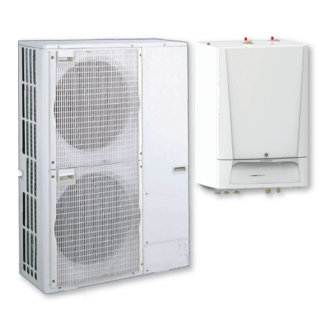
- Page 1 ADVANCE User Guide Reversible air/water "Split Inverter" heat pump HPI S MIT-S 4-8/E MIT-S 11-16/E MIT-S 22-27/E MIT-S 4-8/H MIT-S 11-16/H MIT-S 22-27/H S U S T A I N A B L E C O M F O R T ®...
- Page 2 Dear Customer, Thank you very much for buying this appliance. Please read through the manual carefully before using the product, and keep it in a safe place for later reference. In order to ensure continued safe and efficient operation we recommend that the product is serviced regularly. Our service and customer service organisation can assist with this.
-
Page 3: Table Of Contents
Contents Contents Safety instructions and recommendations ..............5 Safety . - Page 4 Contents 6.1.2 Error codes ................28 6.1.3 SCB-10 error codes .
-
Page 5: Safety Instructions And Recommendations
1 Safety instructions and recommendations Safety instructions and recommendations Safety Operation Danger This appliance can be used by children aged from 8 years and above and persons with reduced physical, sensory or mental capabilities or lack of experience and knowledge if they have been given supervision or instruction concerning use of the appliance in a safe way and understand the haz... -
Page 6: General Instructions
1 Safety instructions and recommendations Domestic wa Caution Draining the domestic hot water tank: 1. Shut off the domestic cold water inlet. 2. Open a hot water tap in the installation. 3. Open a valve on the safety unit. 4. When the water stops flowing, the domestic hot water tank has been drained. -
Page 7: Refrigerant Safety
1 Safety instructions and recommendations Danger Danger of electric shock: the length of the conductors between the traction arrester device and the terminal blocks must be such that the active conductors are put under tension before the earth conductor. Only qualified professionals may carry out electrical connections, always with the power off. -
Page 8: Hydraulic Safety
1 Safety instructions and recommendations The hydraulic installation must be capable of handling a minimum flow rate at all times. Heating water and domestic water must not come into contact with each other. Domestic water must not circulate through the exchanger. Limit temperature at the draw-off point: the maximum domestic hot water temperature at the draw-off point is subject to special regulations in the various countries in which the appliance is sold in order to protect the... -
Page 9: Liabilities
1 Safety instructions and recommendations Wait for approx. 20-30 seconds for the outdoor unit capacitors to be discharged, and check that the lights on the outdoor unit PCBs have gone out. Before working on the refrigeration circuit, switch off the appliance and wait a few minutes. -
Page 10: Symbols Used In The Manual
2 Symbols used in the manual Symbols used in the manual This manual uses various danger levels to draw attention to special instructions. We do this to improve user safety, to prevent problems and to guarantee correct operation of the appliance. Danger Risk of dangerous situations that may result in serious personal injury. -
Page 11: Technical Specifications
3 Technical specifications Technical specifications Homologations 3.1.1 Directives This product complies with the requirements of the following European Directives and Standards: Pressure Equipment Directive 2014/68/EU Low Voltage Directive 2014/35/EU Generic standard: EN 60335-1 Relevant standards: EN 60335-2-40, EN 60335-2-21 Electromagnetic Compatibility Directive 2014/30/EU Generic standards: EN 61000-6-3, EN 61000-6-1 Relevant Standard: EN 55014 This product complies with the requirements of European Directive... - Page 12 3 Technical specifications Tab.2 Outdoor unit conditions of use Limit operating temperatures AWHP 4.5 AWHP 6 AWHP 8 AWHP 11 AWHP 16 AWHP 22 AWHP 27 MR-3 MR-2 MR-2 MR-2 TR–2 TR–2 AWHP 11 AWHP 16 TR-2 TR-2 Water in heating mode +18 °C/ +18 °C/ +18 °C/...
-
Page 13: Heat Pump Weight
3 Technical specifications Tab.6 Cooling mode: outside air temperature +35 °C, water temperature at the outlet +18 °C. Performances in accordance with EN 14511-2. Measurement type Unit AWHP AWHP 6 AWHP 8 AWHP AWHP AWHP AWHP AWHP AWHP 4.5 MR MR-3 MR-2 11 MR-2... -
Page 14: Combination Heaters With Medium-Temperature Heat Pump
3 Technical specifications Tab.9 Outdoor unit Outdoor unit Unit AWHP AWHP 6 AWHP 8 AWHP AWHP AWHP AWHP AWHP AWHP 4.5 MR MR-3 MR-2 11 MR-2 11 TR-2 16 MR-2 16 TR-2 22 TR–2 27 TR–2 Weight 3.3.3 Combination heaters with medium-temperature heat pump Tab.10 Technical parameters for heat pump combination heaters (parameters declared for medium-temperature application) - Page 15 3 Technical specifications Product name AWHP 4.5 AWHP 6 AWHP 8 MR-3 MR-2 Crankcase heater mode 0.000 0.055 0.055 Supplementary heater Psup Rated heat output Type of energy input Electricity Electricity Electricity Other specifications Capacity control Variable Variable Variable Sound power level, indoors - outdoors 43 - 58 43 - 65 51 - 65...
- Page 16 3 Technical specifications Product name AWHP 11 MR-2 AWHP 16 MR-2 AWHP 11 TR-2 AWHP 16 TR-2 Electrical power consumption Off mode 0.009 0.009 Thermostat-off mode 0.049 0.035 Stand-by 0.021 0.021 Crankcase heater mode 0.055 0.055 Supplementary heater Psup Rated heat output Type of energy input Electricity Electricity...
-
Page 17: Circulating Pump
3 Technical specifications Product name AWHP 22 TR–2 AWHP 27 TR–2 COPd = bivalent temperature 1.64 1.67 COPd = operation limit temperature 2.80 2.86 Operation limit temperature for air-to-water heat pumps °C Heating water operating limit temperature WTOL °C Electrical power consumption Off mode 0.010 0.014... -
Page 18: Operation
4 Operation Operation Control panel description 4.1.1 Description of the user interface Fig.2 1 Rotary knob to select a menu or setting 2 Validation button 3 Back key to return to the previous level or previous menu 4 Main menu key 5 Display screen 6 LED for status indication: continuous green = normal operation... -
Page 19: Starting And Stopping The Heat Pump
4 Operation Icon Information Description of the icon DHW tank Temperature display for the domestic hot water Outdoor temperature Outdoor temperature display Starting and stopping the heat pump 4.2.1 Starting the heat pump 1. Switch on the outdoor unit and the indoor unit. The heat pump will begin an automatic vent programme (which lasts approx. -
Page 20: Regional And Ergonomic Parameters
4 Operation 2. Set the following parameters: Tab.14 Parameter Description Start date holiday Set the date and time for the start of the absence period. End date holiday Set the date and time for the end of the absence period. Wished room temperature during holiday Set the desired room temperature for the absence period Reset... -
Page 21: Personalising The Activities
4 Operation 1. Select the icon for the zone to be modified, , for example. 2. Select Zone configuration > Zone friendly Name. 3. Modify the name of the zone (20 characters max.). 4. Select Icon display zone 5. Select the symbol to be associated with the zone. 6. -
Page 22: Room Temperature For A Zone
4 Operation Room temperature for a zone 4.8.1 Selecting the operating mode To set the room temperature for the different living zones, you can choose between five operating modes. We recommend the Scheduling operating mode which enables the room temperature to be modulated according to your needs and to optimise your energy consumption. -
Page 23: Changing The Room Temperature Temporarily
4 Operation 1. Select the icon for the zone to be programmed, , for example. Information on the current operating mode is given in the upper part of the screen. Fig.7 2. To modify the timer programme for the Cooling mode, select Zone configuration >... -
Page 24: Forcing Domestic Hot Water Production (Override)
4 Operation 1. Select the DHW tank icon. Information on the current operating mode is given in the upper part of the screen. 2. To activate the timer programming or to change the timer programme, select Scheduling. 3. Select the timer programme to be activated. Information on the active timer programme is given in the upper part of the screen. - Page 25 4 Operation 1. Select the Air Src Heat pump icon. 23.5 The energy consumed since the last energy consumption meter reset is displayed: Tab.20 Parameter Description Cool Energy consumed Energy consumed for cooling DHW energy consumed Energy consumed for domestic hot water CH Energy Consumed Energy consumed for central heating 2.
-
Page 26: Maintenance
5 Maintenance Maintenance General Maintenance operations are important for the following reasons: To guarantee optimum performance. To extend the life of the equipment. To provide an installation which offers the user optimum comfort over time. Caution Only qualified professionals are authorised to carry out maintenance work on the heat pump and the heating system. -
Page 27: Check The Hydraulic Pressure
5 Maintenance 2. Consult the information linked to the maintenance and servicing of your appliance: Information Description Maintenance required Indicates the necessity of mainte nance: yes/no Current maintenance Type of maintenance to come Service run hours Number of hours that the appliance has been producing energy since last service Hours since service... -
Page 28: Troubleshooting
6 Troubleshooting Troubleshooting Resolving operating errors If your appliance malfunctions, the status LED flashes and/or changes colour and a message containing an error code is displayed on the main screen of the control panel. This error code is important for the correct and rapid diagnosis of the type of malfunction and for any technical assistance that may be needed. -
Page 29: Scb-10 Error Codes
6 Troubleshooting Error Message Description code H02.03 Conf Error Configuration Error H02.04 Parameter Error Parameter Error H02.05 CSU CU mismatch CSU does not match CU type H02.07 Water Press Error Water Pressure Error active Check the hydraulic pressure in the heating circuit. H02.09 Partial block Partial blocking of the device recognized... - Page 30 6 Troubleshooting Code Display text Description H00.78 TcascadeFlow missing Cascade Flow temperature sensor was expected but not detected H02.02 Wait Config Number Waiting For Configuration Number H02.03 Conf Error Configuration Error H02.04 Parameter Error Parameter Error H02.05 CSU CU mismatch CSU does not match CU type H02.16 Int CSU Timeout...
-
Page 31: Fault Codes
6 Troubleshooting 6.1.4 Fault codes If a fault code is still present after several automatic start-up attempts, the heat pump switches to error mode. The heat pump will only resume normal operation once the causes of the fault have been eliminated by the installer. When one of the following codes is displayed and the heat pump cannot restart automatically, contact a maintenance technician. -
Page 32: Fault Finding
6 Troubleshooting Tab.26 Code Display text Description A00.32 TOutside Open Outside temperature sensor is either removed or measures a temperature below range A00.33 TOutside Closed Outside temperature sensor is either shorted or measures a temperature above range A00.34 TOutside Missing Outside temperature sensor was expected but not detected A02.18 OBD Error... - Page 33 6 Troubleshooting Problems Probable causes Corrections The heat pump does The heating set point tem Increase the value of the room temperature set point or, if a room ther not work. perature is too low. mostat is connected, increase the temperature on it. The heat pump is not op...
-
Page 34: Decommissioning And Disposal
7 Decommissioning and disposal Decommissioning and disposal Decommissioning procedure To decommission the heat pump temporarily or permanently: 1. Contact the installer. Disposal and recycling Fig.9 Warning Removal and disposal of the heat pump must be carried out by a qualified professional in accordance with prevailing local and national regulations. -
Page 35: Energy Savings
8 Energy savings Energy savings Energy-saving advice: Do not block ventilation outlets. Do not cover the radiators. Do not hang curtains in front of the radiators. Install reflective panels behind the radiators to prevent heat losses. Insulate the pipes in rooms that are not heated (cellars and lofts). Close the radiators in rooms not in use. -
Page 36: Product Fiche And Package Fiche
9 Product fiche and package fiche Product fiche and package fiche Compatible heating devices Tab.28 Outdoor unit Associated/compatible indoor units AWHP 4.5 MR MIT-S 4-8/E MIT-S 4-8/H AWHP 6 MR-3 MIT-S 4-8/E MIT-S 4-8/H AWHP 8 MR-2 MIT-S 4-8/E MIT-S 4-8/H AWHP 11 MR-2 MIT-S 11-16/E MIT-S 11-16/H... -
Page 37: Product Fiche - Temperature Controls
9 Product fiche and package fiche AWHP 11 AWHP 11 AWHP 16 AWHP 16 MR-2 TR-2 MR-2 TR-2 Annual energy consumption 3999 3999 5861 5861 Sound power level L indoors dB (A) Rated heat output, under colder - warmer climate condi 4 - 8 4 - 8 7 - 13... - Page 38 9 Product fiche and package fiche Fig.10 Package fiche for medium-temperature heat pumps indicating the space heating energy efficiency of the package Seasonal space heating energy effi ciency of heat pump ‘I’ Temperature control Class I = 1%, Class II = 2%, Class III = 1.5%, Class IV = 2%, Class V = 3%, Class VI = 4%, from fi...
- Page 39 9 Product fiche and package fiche Tab.33 Weighting of medium temperature heat pumps II, package without hot water storage tank II, package with hot water storage tank Prated / (Prated + Psup) (1)(2) 1.00 1.00 0.70 0.63 0.45 0.30 0.25 0.15 0.15 0.06...
-
Page 40: 10 Appendix
10 Appendix 10 Appendix 10.1 Name and symbol of the zones Tab.36 Name and symbol of the zones Factory-set name Factory-set symbol Name and symbol defined by the customer CIRCA0 CIRCA1 CIRCB1 CIRCC1 CIRCAUX1 10.2 Name and temperature of the activities Tab.37 Name and temperature of the activities for heating Factory-set name... - Page 41 10 Appendix 7684505 - v03 - 14052020 MIT-S...
- Page 42 10 Appendix MIT-S 7684505 - v03 - 14052020...
- Page 43 © Copyright All technical and technological information contained in these technical instructions, as well as any drawings and technical descriptions supplied, remain our property and shall not be multiplied without our prior consent in writing. Subject to alterations.
- Page 44 57, rue de la Gare - F-67580 Mertzwiller 03 88 80 27 00 SERVICE CONSOMMATEURS 0 825 120 520 0,15 / min 03 88 80 27 99 www.dedietrich-thermique.fr VAN MARCKE NV 000 «БДP T » LAR Blok Z, 5 129164, Россия, г. Москва B- 8511 KORTRIJK Зубарев...
Need help?
Do you have a question about the HPI S and is the answer not in the manual?
Questions and answers