
Related Manuals for ICP DAS USA LP-22 Series


Summary of Contents for ICP DAS USA LP-22 Series
- Page 1 LinPAC AM335x Series User Manual V2.0.1 Apr 2019 LP-22xx/LP-52xx Series LP-8x2x Series LP-9x2x Series...
- Page 2 Warranty All products manufactured by ICP DAS Inc. are warranted against defective materials for a period of one year from the date of delivery to the original purchaser. Warning ICP DAS Inc. assume no liability for any damage consequent to the use of this product.
-
Page 3: Table Of Contents
Contents 1. Introduction ............................. 7 1.1. Features ..........................8 2. LinPAC AM335x Getting Started ....................10 2.1. Mounting the Hardware ..................... 10 2.1.1. Mounting the LP-22xx ....................10 2.1.2. Mounting the LP-52xx ....................11 2.1.3. Mounting the LP-8x2x ....................13 2.1.4. - Page 4 3.1.4. rmdir: deletes the subdirectory which must be empty (Equivalent DOS Command: rd) ..................54 3.1.5. rm: deletes (removes) the file or directory (Equivalent DOS Command: delete) ... 54 3.1.6. cp: copies one or more files (Equivalent DOS Command: copy) ......54 3.1.7.
- Page 5 4.3.3. Execute Demo- helloworld.exe ................75 4.3.4. Execute the application on LinPAC AM335x PAC at boot time ....... 80 5. Application for LinPAC AM335x PAC ..................... 81 5.1. Package management with APT ..................81 5.2. SFTP(secure file transfer program) ..................82 5.3.
-
Page 6: Version 2.0.1 Page
B. I-9K Modules and I-97K Modules ..................128 C. XV-Board Modules .......................129 D. Revision History ........................130 AM335X-PAC Series User Manual version 2.0.1 Page: 6 Copyright © 2019 ICP DAS Co., Ltd. All Rights Reserved. E-mail: service@icpdas.com... -
Page 7: Introduction
1. Introduction This chapter introduces the fundamental concepts for the user with the LinPAC AM335x series. LinPAC AM335x series is the new generation Linux-based PAC (Programmable Automation Controller) from ICP DAS and is equipped with a Cortex-A8 CPU (1.0 GHz) running a Linux kernel 3.x operation system, multiple communication interfaces and slots for high performance parallel I/O modules and serial I/O modules. -
Page 8: Features
1.1. Features The LinPAC AM335x PAC offers the most comprehensive configuration and remote system upgrade solutions to meet specific application requirements. The following list shows the hardware and software features designed to simplify installation, configuration and application. Powerful CPU Module - AM335x ARM Cortex-A8 (1.0 GHz) ... - Page 9 For full details of specifications which can be found at: LinPAC-22xx series: http://ftp.icpdas.com.tw/pub/cd/linpac/napdos/lp-2000/lp-2x41/lp-2241/document/data_sheet/ LinPAC-52xx series: http://ftp.icpdas.com.tw/pub/cd/linpac/napdos/lp-5000/lp-52xx/lp-5231/document/data_sheet/ LinPAC-8x2x series: http://ftp.icpdas.com.tw/pub/cd/linpac/napdos/lp-8x2x/document/data_sheet/ LinPAC-9x2x series: http://ftp.icpdas.com.tw/pub/cd/linpac/napdos/lp-9x2x/document/data_sheet/ Please note: The flash and microSD disk have a finite number of program-erase cycles. Important information should always be backed up on other media or storage device for long-term safekeeping.
-
Page 10: Linpac Am335X Getting Started
2. LinPAC AM335x Getting Started This chapter provides a guided tour of the LinPAC AM335x series PAC installation and configuration that describes the steps needed to download, install, configure, and run the basic procedures for the user working with the in LinPAC AM335x PAC for the first time. 2.1. -
Page 11: Mounting The Lp-52Xx
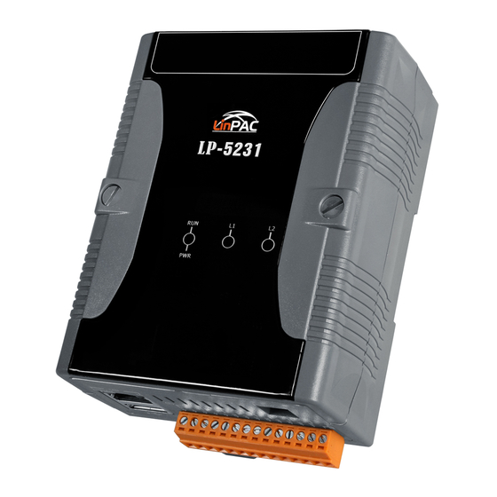
2.1.2. Mounting the LP-52xx DIN-Rail mounting The LP-5231 has simple rail clips for mounting reliably on a standard 35 mm DIN-Rail. AM335X-PAC Series User Manual version 2.0.1 Page: 11 Copyright © 2019 ICP DAS Co., Ltd. All Rights Reserved. E-mail: service@icpdas.com... - Page 12 Remove the LP-5231 from the DIN-Rail Wall/Panel mounting The LP-5231M/LP-5231PM-3GWA/LP-5231PM-4GE/LP-5231PM-4GC can be mounted either directly to a wall/panel. Step 1: Install the four mounting screws into the 4 keyhole mounting holes. Step 2: Fasten the screws securely. AM335X-PAC Series User Manual version 2.0.1 Page: 12 Copyright ©...
-
Page 13: Mounting The Lp-8X2X
2.1.3. Mounting the LP-8x2x Wall/Panel mounting The LP-8x2x can be mounted either directly to a wall/panel or onto a standard 35mm DIN-Rail. Step 1: Install the four mounting screws into the 4 keyhole mounting holes. Step 2: Fasten the screws securely. Tips &... - Page 14 DIN-Rail mounting Step 1: Hook upper tab over upper flange of DIN-Rail. Step 2: Tilt the module toward DIN-Rail until it snaps securely to DIN-Rail. AM335X-PAC Series User Manual version 2.0.1 Page: 14 Copyright © 2019 ICP DAS Co., Ltd. All Rights Reserved. E-mail: service@icpdas.com...
- Page 15 Tips & Warnings A good common ground reference (earth ground) is essential for proper operation of the LP-8x2x. One side of all control circuits, power circuits, and the ground lead must be properly connected to earth ground by either installing a ground rod in close proximity to the enclosure or by connecting to the incoming power system ground.
-
Page 16: Mounting The Lp-9X2X
2.1.4. Mounting the LP-9x2x Wall/Panel mounting The LP-9x2x can be mounted either directly to a wall/panel, or onto a stainless 35mm DIN-Rail. Step 1: Install the four mounting screws into the 4 keyhole mounting holes. Step 2: Fasten the screws securely. Tips &... - Page 17 Step 3: Connect the ground lead to the frame ground point. Tips & Warnings A good common ground reference (earth ground) is essential for proper operation of the LP-9x2x. One side of all control circuits, power circuits, and the ground lead must be properly connected to earth ground by either installing a ground rod in close proximity to the enclosure or by connecting to the incoming power system ground.
- Page 18 Step 2: Clip the device onto a stainless DIN-Rail. Tips & Warnings For DIN-Rail mounting, it is strongly recommended that only a stainless steel DIN-Rail be used to support the weight of the LP-9x2x system, providing stability and preventing LP-9x2x from leaning. AM335X-PAC Series User Manual version 2.0.1 Page: 18...
- Page 19 Step 3: Connect the ground lead to the frame ground point. Tips & Warnings A good common ground reference (earth ground) is essential for proper operation of the LP-9x2x. One side of all control circuits, power circuits, and the ground lead must be properly connected to earth ground by either installing a ground rod in close proximity to the enclosure or by connecting to the incoming power system ground.
- Page 20 2.1.4.1. Installing the RJ-45 waterproof connector assembly The LP-9x2x series is equipped with an RJ-45 waterproof connector to withstand contaminant in the dusty environment. The RJ-45 waterproof connector is optional for use with LAN1 port. If you do not need the RJ-45 waterproof connector, you can remove the cap and just plug in a regular Ethernet cable.
- Page 21 Step 3: Wrap the (E) panel gasket base around the (D) cable gland base. Step 4: Wrap the (C) clamping ring around the (D) cable gland base. Step 5: Insert the (B) rubber sealing insert into the (D) cable gland base. AM335X-PAC Series User Manual version 2.0.1 Page: 21...
- Page 22 Step 6: Push the (A) sealing nut forward and Hand-tighten it to seal the assembly. Step 7: Insert the RJ-45 cable into the RJ-45 connector. Step 8: Push the RJ-45 waterproof connector assembly forward. Step 9: Insert the Ethernet cable and screw the RJ‐45 waterproof into the receptacle. AM335X-PAC Series User Manual version 2.0.1 Page: 22...
-
Page 23: Deploying A Basic System
2.2. Deploying a Basic System The LinPAC AM335x series PAC provides a variety of communication interface to suit a range of application. Here is a simple application for using the LP-22xx/52xx/8x2x/9x2x. Tips & Warnings 1. The input range of power supply is +10 V to +30 V for LP-8x2x/9x2x and +12 V... -
Page 24: Installation For Lp-22Xx
2.2.1. Installation for LP-22xx Connecting to a PC, the USB device, and the power supply. Step 1: Connect the positive terminal (+) of the power supply to the terminal PWR and the negative terminal (-) of the power supply to the P.GND. Step 2: Connect the USB mouse or the USB keyboard to the USB port. -
Page 25: Installation For Lp-52Xx
2.2.2. Installation for LP-52xx Connecting to a PC, the USB device, and the power supply. Step 1: Connect the positive terminal (+) of the power supply to the terminal PWR and the negative terminal (-) of the power supply to the P.GND. Step 2: Connect the USB mouse or the USB keyboard to the USB port. -
Page 26: Installation For Lp-8X2X
2.2.3. Installation for LP-8x2x Connecting to a PC, the USB device, and the power supply. Step 1: Connect the positive terminal (+) of the power supply to the terminal PWR1/2 and the negative terminal (-) of the power supply to the P.GND. Step 2: Connect the USB mouse or the USB keyboard to the USB port. -
Page 27: Installation For Lp-9X2X
2.2.4. Installation for LP-9x2x Connecting to a PC, the USB device, and the power supply. Step 1: Connect the positive terminal (+) of the power supply to the terminal PWR1/2 and the negative terminal (-) of the power supply to the P.GND. Step 2: Connect the USB mouse or the USB keyboard to the USB port. -
Page 28: Inserting The I/O Modules
Step 4: Connect to PC or the laptop to the LAN port via an Ethernet switch. 2.3. Inserting the I/O Modules LinPAC controller is equipped with rich I/O expansion ability, all kinds of I/O modules as described in the following: Number of RS-232 I-8K and I-9K and... -
Page 29: Adding An I/O Device For Lp-22Xx
2.3.1. Adding an I/O Device for LP-22xx 2.3.1.1. Installing the XV-Board LP-22xx has one expansion I/O slots to expand the functions. For more information about the I/O expansion modules that are compatible with the LP-22xx, please refer to: http://www.icpdas.com/root/product/solutions/hmi_touch_monitor/touchpad/xv-board_selection.html Step 1: Remove stripped screws and then remove the cover. Step 2: Hold the XV-board vertically and align the socket, and then carefully press the XV-board onto the socket. - Page 30 Step 3: Close the cover and then fasten the screws. Step 4: Insert the I/O terminal and then stick the I/O sticker. AM335X-PAC Series User Manual version 2.0.1 Page: 30 Copyright © 2019 ICP DAS Co., Ltd. All Rights Reserved. E-mail: service@icpdas.com...
-
Page 31: Adding An I/O Device For Lp-52Xx
2.3.2. Adding an I/O Device for LP-52xx 2.3.2.1. Installing the XV-Board LP-52xx has one expansion I/O slots to expand the functions. For more information about the I/O expansion modules that are compatible with the LP-52xx, please refer to: http://www.icpdas.com/root/product/solutions/hmi_touch_monitor/touchpad/xv-board_selection.html Step 1: Remove stripped screws and then remove the cover. Step 2: Hold the XV-board vertically and align the socket, and then carefully press the XV-board onto the socket. - Page 32 Step 3: Close the cover and then fasten the screws. Step 4: Insert the I/O terminal and then stick the I/O sticker. AM335X-PAC Series User Manual version 2.0.1 Page: 32 Copyright © 2019 ICP DAS Co., Ltd. All Rights Reserved. E-mail: service@icpdas.com...
- Page 33 2.3.2.2. Inserting the SIM card The SIM card tray is located on the top side of the module. The eject button is on the right side of the tray door. Step 1: Push the ejection button until the SIM card tray pops out. Step 2: Pull out the tray completely and set it on a flat surface.
-
Page 34: Adding An I/O Device For Lp-8X2X
2.3.3. Adding an I/O Device for LP-8x2x All I/O Web Page include the I/O module specifications, pin assignments and wiring connections. For example, Pin Assignments and Wiring connections for the I-87054W module are as follows: http://www.icpdas.com/root/product/solutions/remote_io/rs-485/i-8k_i-87k/i-87054w.html Step 1: Align circuit card with slot and press firmly to seat module into connector. Tips &... -
Page 35: Adding An I/O Device For Lp-9X2X
Step 3: Attach field wiring using the terminal block, and then insert the terminal block. 2.3.4. Adding an I/O Device for LP-9x2x LP-9000 has 2/4/8 I/O expansion slots to support I-9K and I-97K series I/O modules. Before choosing the right I/O modules, you first need to know the I/O expansion capacities in order to choose the best expansion module for achieving maximal efficiency. - Page 36 Step 1: Insert the I/O module. Tips & Warnings If you do not expand the I/O module full, please keep the top case of the unused slot to protect the backplane from dirt, dust and damage from foreign objects. Step 2: Wiring connection. The metal part of the cord end terminal on the wire can be direct wired to the terminal of LP-9x2x.
-
Page 37: Console Port Connection
2.4. Console Port Connection The LinPAC AM335x PAC support remote connection from the ‘Console’ port. The user can follow below steps to connect to the LinPAC AM335x PAC. Step 1: User can choose the software (Putty or others) through the ‘Console’ to connect the LinPAC AM335x PAC. -
Page 38: Lan1/Lan2 Network Configuration
2.5. LAN1/LAN2 Network Configuration After logging into the LinPAC AM335x PAC successfully, the user can use ‘ifconfig’ command to get the IP address of LAN1/LAN2. The LAN 1/2 of factory setting use DHCP. If user would prefer to setup the IP address for static mode, the following steps for reference: Step 1: Using the Linux command ‘vi’... -
Page 39: Lan1/Lan2 Network Connection
2.6. LAN1/LAN2 Network Connection The user can use ‘ifconfig’ command to get the IP address of LAN1/LAN2 and the SSH client software (Putty or others) to connect the LinPAC AM335x PAC. Step 1: Using ‘ifconfig’ command to check the IP address of LAN1/2. (Refer to the Figure 2.6-1) Figure 2.6-1. -
Page 40: Overview Of The Serial Ports
2.7. Overview of the Serial Ports The following is a description of the functionality for the three serial ports contained in the LinPAC AM335x series embedded controller, and are based on the RS-232 or RS-485 interfaces. 2.7.1. Introduction to Serial port for LP-22xx The following illustrates the ports contained on the LP-22xx. -
Page 41: Introduction To Serial Port For Lp-52Xx
2.7.2. Introduction to Serial port for LP-52xx The following illustrates the ports contained on the LP-52xx. The information is organized as follows table: Default Device name Definition in LP-52xx SDK Description Baud rate Internal communication with the /dev/ttyO1 or COM1 115200 XV-board modules RS-232 (RxD, TxD and GND);... -
Page 42: Introduction To Serial Port For Lp-8X2X
2.7.3. Introduction to Serial port for LP-8x2x Figure 2.7.3-1 illustrates the ports contained on the LP-8821 and Figure 2.7.3-2 illustrates those on the LP-8121. The information is organized as follows: ttyO4─ Internal communication with the I-87KW modules in slots ... -
Page 43: Introduction To Serial Port For Lp-9X2X
Figure 2.7.3-2. Serial port mapping on the LP-8121 2.7.4. Introduction to Serial port for LP-9x2x Figure 2.7.4-1 illustrates the ports contained on the LP-9821. The information is organized as follows: ttyO4─ Internal communication with the I-97KW modules in slots ... -
Page 44: Accessing The Common Serial Ports
Figure 2.7.4-1. Serial port mapping on the LP-9821 2.7.5. Accessing the common serial ports 2.7.5.1. Internal communication for COM1 port The COM1 port is an internal I/O expansion port on the LinPAC and is used to connect to the series module inserted into the LinPAC embedded controller. The I-87K, I-97K and XV-board series is based on a serial interface, which is provided for combining a variety of I/O function within the LP-8x2x, LP-9x2x and LP-22xx/52xx controllers. - Page 45 A serial command must be used to control the I-87KW/97K series module. For more information about serial command usage, see the chapter 3.2. i-Talk Utility. To control the series module, the Com port parameters and call the Open_Com() function to open the COM1 port based on the appropriate settings.
- Page 46 2.7.5.2. RS-232 port The following is RS-232 serial port for the LP-22xx, LP-52xx, LP-8x2x and LP-9x2x, as illustrated in Figures 2.7.5.2-1, 2.7.5.2-2 and 2.7.5.2-3 below. COM4 Figure 2.7.5.2-1. COM4 serial port for the LP-22xx COM4 Figure 2.7.5.2-2. COM4 serial port for the LP-52xx AM335X-PAC Series User Manual version 2.0.1 Page: 46...
- Page 47 Figure 2.7.5.2-3. COM3 and COM36 serial port for the LP-8x2x/9x2x This /dev/ttyS1, /dev/ttyS34 or /dev/ttyO4 port is located on the right-upper corner on the LP-22xx, LP-52xx, LP-8x2x and LP-9x2x and is a standard RS-232 serial port that provides TxD, RxD, RTS, CTS, GND, non-isolated and a maximum speed of 115200 bps.
- Page 48 (A) Open ‘Hyper Terminal’ on the Host PC to monitor the test process. The default settings for COM3 port are 9600, 8, N, 1 (B) Send data via /dev/ttyS1 port: On the LP-8x21: Type the command: echo send-232 >/dev/ttyS1 Check that the word ‘send-232’ is displayed on the ‘Hyper Terminal’ screen on the PC (C) Receive data via the /dev/ttyS1 port: On the LP-8x21: Type the command:...
- Page 49 2.7.5.3. RS-485 port The following is 2-wire RS-485 serial port for the LP-22xx, LP-52xx, LP-8x2x and LP-9x2x, as illustrated in Figures 2.7.5.3-1, 2.7.5.3-2 and 2.7.5.3-4 below. COM2 COM5 Figure 2.7.5.3-1. RS-485 connections of COM2 and COM5 for LP-22xx COM5 COM2 Figure 2.7.5.3-2.
- Page 50 Use the ‘setexdo’ command to set digital output value to a serial module. (Refer to Figure 2.7.5.3-3) Figure 2.7.5.3-3. Using the command line to test on LP-5231 Figure 2.7.5.3-4. RS-485 connections of COM2 for LP-8x2x/9x2x This port provides RS-485 serial communication functionality (DATA+ and DATA-) and is located on the bottom-right corner on the LP-22xx, LP-52xx, LP-8x2x and LP-9x2x.
- Page 51 Test using C language: unsigned char port=36; DWORD baudrate=9600; char data=8, parity=0, stopbit=1; Open_Com(port, baudrate, data, char parity, stopbit); // send command… Test using command line: (PC <--> i-7520 <--> /dev/ttyS on the LP-8x21 - see Figure 2.7.5.3-5) (A) Open ‘Hyper Terminal’...
-
Page 52: Serial Port Configuration
Receive data via the COM2 port Send information via COM1 por of PC Figure 2.7.5.3-5. Using the command line to test 2.7.6. Serial Port configuration Use the ‘stty’ command to query or configure the COM port. For example, to modify the baud rate 9600 to 115200 bps via /dev/ttyS1 port:... -
Page 53: Instructions For Linpac Am335X Pac
3. Instructions for LinPAC AM335x PAC This chapter provides a brief introduction of the LinPAC AM335x PAC service tools and its benefits. There are several tools and utilities built-in and designed for use with LinPAC AM335x PAC. Some of these are pre-installed on LinPAC AM335x PAC and can work directly on LinPAC AM335x PAC, and some of these are supporting tools and can help you to manage the LinPAC AM335x PAC remotely on a PC. -
Page 54: Mkdir: Creates A Subdirectory (Equivalent Dos Command: Md)
3.1.3. mkdir: creates a subdirectory (Equivalent DOS Command: md) Parameter Description Example No error if the subdirectory exists, and creates the parent mkdir -p directory directories as needed 3.1.4. rmdir: deletes the subdirectory which must be empty (Equivalent DOS Command: rd) Parameter Description Example... -
Page 55: Chmod: Changes The Access Permissions For A File
3.1.10. chmod: changes the access permissions for a file Syntax: chmod ??? file → ??? means owner: group: all users For example: chmod 754 test.exe 7 5 4 → 111 (read, write, execute) 101 (read, write, execute) 100 (read, write, execute) The first number 7: the owner can read and write and execute files The second number 5: the group can only read and execute files The third number 4: all users can only read files... -
Page 56: Hwclock: Queries And Sets The Hardware Clock (Rtc)
3.1.16. hwclock: queries and sets the hardware clock (RTC) Parameter Description Example Reads the hardware clock and prints the time on a standard hwclock -r output. –w Sets the hardware clock to the current system time hwclock -w 3.1.17. netstat: displays the current state of the network Parameters: [-a]: list all states (For example: netstat -a) 3.1.18. -
Page 57: Update-Rc.d: Install And Remove System-V Style Init Script Links
3.1.24. update-rc.d: install and remove System-V style init script links update-rc.d [-n] name defaults (Example: update-rc.d hello defaults) update-rc.d [-n] [-f] name remove (Example: update-rc.d –f hello remove) AM335X-PAC Series User Manual version 2.0.1 Page: 57 Copyright © 2019 ICP DAS Co., Ltd. All Rights Reserved. E-mail: service@icpdas.com... -
Page 58: I-Talk Utility
3.2. i-Talk Utility The i-Talk utility can make the convenient for users to access the modules and hardware in the LinPAC AM335x PAC and can be found in the path /usr/sbin/iTalk. An overview of the i-Talk utility functions is given below: ... - Page 59 Below table lists the demos that show how to use the I-talk utility. In the demo, the I-8024W ( AO Module ), I-8017HW ( AI Module ) and I-8055W ( DIO Module) are all used and they are plugged into the slots 1, 2 and 3 of the LinPAC separately. Typing the name of the instruction will display usage details for the instruction.
- Page 60 LP-22xx/52xx Instruction Description setxvdo Set digital output value to XV-Board setxvao Set analog output value to XV-Board getxvdi Get digital input value from XV-Board getxvai Get analog input value from XV-Board getxvdo Get digital output value from XV-Board getxvao Get analog output value from XV-Board setmodbus Set a Modbus command to modbus device...
-
Page 61: Getting Started With The Linpac Am335X Sdk
4. Getting started with the LinPAC AM335x SDK The ‘LinPAC_AM335x SDK’ is a development toolkit provided by ICP DAS, which can be used to easily develop custom applications for the LP-22xx/52xx/8x2x/9x2x embedded controller platform. The toolkit consists of the following items: ... -
Page 62: Introduction Of The Linpac Am335X Sdk
4.1. Introduction of the LinPAC AM335x SDK This section will discuss some of the techniques that are adopted in the LinPAC_AM335x SDK, including detailed explanations that describe how to easily use the LinPAC_AM335x SDK. The LinPAC_AM335x SDK is based on Cygwin and is also a Linux-like environment for Microsoft Windows systems, and provides a powerful GCC cross-compiler and an IDE (Integrated Development Environment) that enables LinPAC_AM335x SDK applications to be quickly developed. -
Page 63: Introduction To Cross-Compilation
4.1.2. Introduction to Cross-Compilation Generally, program compilation is performed by running a compiler on the build platform. The compiled program will then run on the target platform. Usually, these two processes are intended for use on the same platform. However, if the intended platform is different, the process is called cross compilation, where source code on one platform can be compiled into executable files to be used on other platforms. -
Page 64: Quick Installation Of The Linpac Am335X Sdk
4.2. Quick Installation of the LinPAC AM335x SDK 4.2.1. Download/Install LinPAC AM335x SDK on Linux 1. To create a ‘icpdas’ folder in root directory, maybe you need to change the root user by ‘sudo’ or ‘su’ command. (Refer to Figure 4.2.1-1) Figure 4.2.1-1. - Page 65 3. Try the following command to decompress file. (Refer to Figure 4.2.1-4) # tar jxvf linpac_am335x_sdk_for_linux.tar.bz2 Figure 4.2.1-4. Decompress ‘.tar.bz2’ file 4. Before compiling the program, you need to set LinPAC_AM335x SDK path in environment variables: using the provided environment variable script, which is called linpac_am335x.sh (Refer to Figure 4.2.1-5).
- Page 66 5. Type ‘make’ on the command line it will execute the compile command according to the Makefile. (Refer to Figure 4.2.1-6) Figure 4.2.1-6. Compiling demo code according to the Makefile AM335X-PAC Series User Manual version 2.0.1 Page: 66 Copyright © 2019 ICP DAS Co., Ltd. All Rights Reserved. E-mail: service@icpdas.com...
-
Page 67: Download/Install Linpac Am335X Sdk On Windows
4.2.2. Download/Install LinPAC AM335x SDK on Windows The LinPAC_AM335x_SDK_for_Windows.exe provides compilers, library, header, examples, and IDE workspace file (for Code::Blocks project). Insert the installation CD into your CD-ROM driver. Open \napdos\LP-9x21\SDK\ folder double-click icon ‘LinPAC_AM335x_SDK_for_Windows.exe’ file, when the Setup Wizard is displayed, click the ‘Next>’... - Page 68 The LinPAC_AM335x SDK files will be extracted and installed and a progress bar will be displayed to indicate the status, refer to Figure 4.2.2-5. Once the software has been successfully installed, click the ‘Finish’ button to complete the development toolkit installation, refer to Figure 4.2.2-6.
- Page 69 From the desktop, double-click the shortcut icon for the ‘LinPAC_AM335x Build Environment’ or click the ‘Start’ > ‘Programs’ > ‘ICPDAS’ > ‘LinPAC_AM335x_SDK’ > ‘LinPAC_AM335x Build Environment’. A Command Prompt window will then be displayed that allows applications for the LinPAC_AM335x to be compiled.
-
Page 70: Integrating Linpac Am335X Sdk With Code::blocks Ide
4.2.3. Integrating LinPAC AM335x SDK with Code::Blocks IDE This tutorial gives you easy-to-follow instructions, with screenshots, for setting up a compiler (the Linaro GCC compiler), a tool that will let you turn the code that you write into programs, and Code::Blocks IDE, a free development environment. - Page 71 Following window will come up (Refer to Figure 4.2.3-2): Figure 4.2.3-2. Startup the LinPAC AM335x SDK Check compiler settings for Linaro GCC cross compiler: Click ‘Settings’ > ‘Compiler’ > ‘Toolchain executables tab’ (Refer to Figure 4.2.3-3): Figure 4.2.3-3. Check compiler settings AM335X-PAC Series User Manual version 2.0.1 Page: 71...
- Page 72 Click Build options, and it will compile the LinPAC_AM335x project completely. (Refer to Figure 4.2.3-4) Figure 4.2.3-4. Compiling a C program 【Note】If you observer some characters may not display properly in cmd.exe, change the code page for the console only, do the following: ...
-
Page 73: Your First Program
4.3. Your First Program In this section, we will introduce how to compile the helloworld.c file to helloworld executable file and executes this on the LinPAC AM335x PAC. In this example, no ICP DAS modules are used. To create a demo program with C language that includes the following main steps: 1. -
Page 74: A Simple Example- Helloworld.c
4.3.1. A simple example- helloworld.c There are three choices available to you: 1. Coding a helloworld.c file 2. To modify/create demo ‘helloworld.c’ Using a programmer's editor, such as PSPad. Create a demo - helloworld.c file. Note that the code is case-sensitive. Refer to Figure 4.3.1-1 for more details. Figure 4.3.1-1. -
Page 75: Compile Demo- Helloworld.c
4.3.2. Compile Demo- helloworld.c Type the command ‘arm-linux-gnueabihf-gcc –o helloworld.exe helloworld.c’ to compile helloworld.c into helloworld.exe, then type ‘dir/w’ or ‘ls’ command to display the contents of the directory and confirm that the helloworld.exe file has been created. (Refer to Figure 4.3.2-1) Figure 4.3.2-1. - Page 76 (2) Before transferring the files to the LP-8x21, type the ‘bin’ command to ensure that the file is transferred to the LP-8x21 in binary mode. (3) Type the command ‘put helloworld.exe’ to transfer the helloworld.exe file to the LP-8x21. (4) Once the message ‘Transfer complete’ is displayed, then transfer process has been completed. To disconnect from the LP-8x21, type the ‘bye’...
- Page 77 <Method two> Using an FTP Client: (1) Open the FTP Software and add an FTP Host to the LP-8x2x. (for example, FileZilla - The free FTP solution for both client and server, https://filezilla-project.org/) (2) Type the User_Name (default value is ‘root’) and Password (default value is ‘icpdas’). Then click the ‘Quickconnect Connect’...
- Page 78 (4) Click the helloworld.exe file in the LP-8x21 to select it and then right-click the file icon and click the ‘File Permissions’ option. In the Properties dialog box, type 777 into the Numeric textbox, and then click the OK button. Refer to Figures 4.3.3-4 and 4.3.3-5 for more details. Figure 4.3.3-4.
- Page 79 Use SSH to access LinPAC and execute program (1) Putty – the free PuTTY is an SSH and telnet client. Download PuTTY tool: http://www.putty.org/ (2) Open a ‘Putty Prompt’ and type the IP Address of the LinPAC, and the connection type is set to SSH.
-
Page 80: Execute The Application On Linpac Am335X Pac At Boot Time
4.3.4. Execute the application on LinPAC AM335x PAC at boot time User can refer to below steps to auto-execute demo ‘helloworld’ at boot time in LinPAC AM335x PAC. 1. Copy SDK demo ‘examples/common/helloworld’ to ‘/usr/sbin’ directory 2. Create script file in ‘/etc/init.d’ directory. Check the ‘/etc/init.d/pppon’ or ‘/etc/init.d/single’ file for an example. -
Page 81: Application For Linpac Am335X Pac
5. Application for LinPAC AM335x PAC In this chapter, ICP DAS provides extra module supported and instructions to enhance LinPAC AM335x PAC functionality and affinity. 5.1. Package management with APT The ‘apt-get’ utility is the Ubuntu package manager used to download and install software packages from local package repositories or ones located on the Internet. -
Page 82: Sftp(Secure File Transfer Program)
5.2. SFTP(secure file transfer program) The LinPAC AM335x series PAC had supported SFTP(or SCP), user can transfer the file from Windows(or Linux). For examples, using Windows Program ‘WinSCP’ to access the device over network, please follow below steps: 1. Choosing the ‘SFTP’ or ‘SCP’ protocol and type IP address, default ID(root) and password(icpdas) to login. -
Page 83: Lamp Server
5.3. LAMP Server The LAMP (Apache2 + PHP5 + MySQL) server has been built in the LinPAC AM335x PAC and it will be started automatically at boot time. As a solution stack, LAMP is suitable for building dynamic web sites and web applications. The default path of web page in the ‘/var/www’ directory. If user want to change the web page’s path, user can use command ‘vi’... -
Page 84: Xfce(Secure File Transfer Program) Gui Desktop
5.4. XFCE(secure file transfer program) GUI Desktop XFCE is a lightweight desktop environment for UNIX-like operating systems. It aims to be fast and low on system resources, while still being visually appealing and user friendly. Now the LinPAC AM335x series Linux provides the XFCE package, after user type ‘root’ and password ‘icpdas’ to login, the local terminal would execute the XFCE Desktop. -
Page 85: Sysvinit Support
5.5. SysVinit Support SysVinit is a system and service manager for Linux operating systems. User can start/stop/enable /disable software service by using Linux command ‘service’ and ‘update-rc.d’. Refer to Figure 5.5-1 and 5.5-2 for more details. Figure 5.5-1. Start/stop software Figure 5.5-2. -
Page 86: Network Support
5.6. Network Support The LinPAC embedded controller already includes a variety of network functions. Following is an overview of the network functions supported in the LinPAC AM335x PAC. 5.6.1. 2G/3G/4G LP-5231PM-3GWM support the 2G/3G system and LP-5231PM-4GE/LP-5231PM-4GC support the 2G/3G/4G system. User can use the command ‘service pppon start’ to start 2G/3G/4G or the command ‘service pppon stop’... -
Page 87: Sms(Short Message Service)
5.6.2. SMS(Short Message Service) The LP-5231PM-3GWA and LP-5231PM-4GE/LP-5231PM-4GC module are equipped with a 3G/4G connection application, meaning that users can download and install software for the purpose of sending short messages via a 2G, 3G, or 4G network. Four SMS tools are available for installation that allows SMS (Short Message Service) applications to be implemented on the LP-5231PM-3GWA and LP-5231PM-4GE/LP-5231PM-4GC module, each of which will be described in more detail below. - Page 88 5.6.2.1. Message in English Sending an English message, users can try the following SMS tools. (a) gsm-utils The gsm-utils binary package provides some simple command line programs that can be used to access a GSM mobile phone via GSM modem. To send an SMS message, using the gsm-utils package, follow the procedure described below.
- Page 89 Step 3: Use the ‘mkdir gnokii’ command to create a folder in the path ‘/root/.config/’, as illustrated in Figure 5.6.2.1-2. Step 4: Use the ‘ln -s /etc/xdg/gnokii/config /root/.config/gnokii’ command to create a symbolic link in the ‘/root/.config/gnokii/’ folder, as illustrated in Figure 5.6.2.1-2. Figure 5.6.2.1-2.
- Page 90 (c) Gammu Gammu is a command line utility that can be used for reading, writing, sending and receiving SMS messages. To send an SMS message using Gammu, follow the procedure described below. Step 1: Use the ‘apt-get install gammu’ command to install the Gammu package. Step 2: Use the ‘gammu-config’...
- Page 91 (d) SMS Server Tools The SMS Server tools package is an SMS Gateway application which can be used to send and receive SMS messages via GSM modems and mobile phones. To send an SMS message via the SMS Server, follow the procedure described below. Step 1: Download the SMS Server Tools package.
- Page 92 Step 4: Use the ‘/etc/init.d/sms3 start’ command to start the SMSD service in the background, as illustrated in Figure 5.6.2.1-9. Step 5: Use the following command to send an SMS message, as illustrated in Figure 5.6.2.1-9. # sendsms 09XXXXXXXX 'smstools : test' Figure 5.6.2.1-9.
- Page 93 5.6.2.2. Messages in Traditional Chinese To send a message in Traditional Chinese, first install the ‘SMS Server tools’ package. For more detailed information regarding the installation of this package, refer to Section (d) of Chapter 5.6.2.1. Before you can send a message in Traditional Chinese the locale configuration for the system must be changed to UTF-8 encoding.
-
Page 94: Linpac Am335X Pac System Settings
6. LinPAC AM335x PAC System Settings The following is a guide to easily configuration the LinPAC AM335x PAC. 6.1. Using a microSD Card When using a microSD card, be sure to pay attention to the following items: 1. Unmount the microSD card before removing it. 2. -
Page 95: Mounting A Microsd Card
(3) Files contained on a mounted microSD card can be accessed from the /mnt/hda directory. (Refer to Figure 6.1-2) Figure 6.1-2. Create and mount a directory named 'had' 6.1.1. Mounting a microSD Card To use a microSD card, insert the microSD card into the socket on the LinPAC AM335x PAC, and it will be automatically mounted when the LinPAC AM335x PAC is booted. -
Page 96: Unmounting The Microsd Card
6.1.2. Unmounting the microSD Card Before removing the microSD card from the LinPAC AM335x PAC, unmount the card by entering the command: # umount /boot/uboot The microSD card can then be safely removed to prevent damage to the card. (Refer to Figure 6.1.2-1) Figure 6.1.2-1. -
Page 97: Scanning And Repairing A Microsd Card
6.1.3. Scanning and repairing a microSD Card After the LinPAC AM335x PAC is booted, the microSD card will be named ‘/dev/mmcblk0p1’. It is recommended that the microSD card is unmounted first before attempting to perform a scan or repair. blockdev: this command is used to call block device ioctls from the command line. -
Page 98: Using A Usb Storage Device
mkfs.minix: this command is used to make a MINIX filesystem Parameter Description Example create a Linux MINIX file-system mkfs.minix /dev/mmcblk0p1 check the device for bad blocks before mkfs.minix -c /dev/mmcblk0p1 building the file system mkfs.vfat: this command is used to make an MS-DOS filesystem Parameter Description Example... -
Page 99: Mounting A Usb Storage Device
6.2.1. Mounting a USB Storage Device To mount a USB storage devices follow the procedure described below: (1) Type ‘mkdir /mnt/usb’ to create a directory named ‘usb’. (2) Type ‘mount /dev/sda1 /mnt/usb’ to mount the USB storage device to the usb directory and then type ‘ls /mnt/usb’... -
Page 100: Wdt
6.3. WDT 6.3.1. WDT for LP-8x2x and LP-9x2x Use the ‘wdt’ command to enable and configure the WDT. There are three steps to this process, which are described below. (1) Enable the WDT. Enable the WDT. The default response time is 10 seconds. # wdt -e ... -
Page 101: Wdt For Lp-22Xx And Lp-52Xx
6.3.2. WDT for LP-22xx and LP-52xx To Enable WDT working status, there are two steps to this process, which are described below. (1) Refresh WDT source. # echo timer > /sys/class/leds/beaglebone::wdt/trigger //Refresh WDT (2) Enable WDT. # echo 0 > /proc/hmistat/radiopower //Enable WDT To Disable WDT working status, there are two steps to this process, which are described below. -
Page 102: Eeprom
6.4. EEPROM To Enable EEPROM working status, there are four steps to this process, which are described below. (1) Startup EEPROM GPIO function. # echo > /sys/class/gpio/export (2) The EEPROM is write protected by default, the user needs to modify default value of EEPROM. # echo >... -
Page 103: Led
6.5. LED Following is the control method of the LinPAC AM335x series PAC LED indicators. 6.5.1. LED Indicators for LP-22xx series The LP-22xx series modules have 6 LED indicators, as illustrated in Figure 6.5.1-1. Figure 6.5.1-1. LED indicators for LP-22xx series LED Indicator Color Meaning... -
Page 104: Led Indicators For Lp-52Xx Series
6.5.2. LED Indicators for LP-52xx series The LP-52xx series modules have 3/4 LED indicators, as illustrated in Figure 6.5.2-1. Figure 6.5.2-1. LED indicators for LP-52xx series LED Indicator Color Meaning The 3G/4G LED indicates that the antenna is 3G/4G Green connected to 3G/4G network. - Page 105 The led_52xx.c demo program illustrates control method of the LP-52xx LED indicator, user can be found demo code in the path C:\cygwin\LinPAC_am335x_SDK\examples\common\led-52xx.c root@LinuxPC-ICPDAS:/icpdas/linpac_am335x_sdk/i8k/examples/common/led-52xx.c Parameter: LED Indicator Parameter LED color Parameter Green AM335X-PAC Series User Manual version 2.0.1 Page: 105 Copyright © 2019 ICP DAS Co., Ltd. All Rights Reserved. E-mail: service@icpdas.com...
-
Page 106: Led Indicators For Lp-8X2X Series
6.5.3. LED Indicators for LP-8x2x series The LP-8x2x series modules have 2 LED indicators, as illustrated in Figure 6.5.3-1. Figure 6.5.3-1. LED indicators for LP-8x2x series LED Indicator Color Meaning Green Power 1 is on. OS is running. User programmable LED indicator. The led_8x2x.c demo program illustrates control method of the LP-8x2x LED indicator, user can be found demo code in the path C:\cygwin\LinPAC_am335x_SDK\examples\common\led-8x2x.c... -
Page 107: Led Indicators For Lp-9X2X Series
6.5.4. LED Indicators for LP-9x2x series The LP-9x2x series modules have 5 LED indicators, as illustrated in Figure 6.5.4-1. Figure 6.5.4-1. LED indicators for LP-9x2x series LED Indicator Color Meaning Power is on. Green OS is running. Orange User programmable LED indicator. The led_9x2x.c demo program illustrates control method of the LP-9x2x LED indicator, user can be found demo code in the path C:\cygwin\LinPAC_am335x_SDK\examples\common\led-9x2x.c... -
Page 108: Additional Support
7. Additional Support This chapter provides additional information related to the modules supported, together with instructions that can be used to enhance the functionality and efficiency of the LinPAC AM335x PAC module. 7.1. Support for N-Port Modules N-port communication modules provide two or four serial ports and can be inserted into the slot of an LP-8x2x/9x2x embedded controller. - Page 109 Figure 7.1-2. The number of each serial port on the I-8112iW modules are presented Figures 7.1-3 and 7.1-4 illustrated the serial port numbers that correspond to the device name on the LP-8x2x. Figure 7.1-3. Device node of I-8114W Figure 7.1-4. Device node of I-8112iW AM335X-PAC Series User Manual version 2.0.1 Page: 109...
- Page 110 Figure 7.1-5. Device slot information for the LP-8121 only The user can type ‘getlist’ to check the module is installed or not, as illustrated in Figure 7.1-6. Figure 7.1-6. Lists the names of all modules inserted Selection guide for Hight-profile I-8K modules: Max.
- Page 111 LP-9x2x The LP-9x2x embedded controller is a multi-tasking uint, meaning that all the serial ports can be controlled simultaneously. The number of each serial port on the I-9114 and I-9144 modules are presented in Figure 7.1-7 and is fixed based on their slot position. Figure 7.1-7.
- Page 112 Check the module is installed or not, and then check the status of the serial port, as illustrated in Figure 7.1-9. Figure 7.1-9. Lists the names of all modules inserted Selection guide for Hight-profile I-9K modules: Max. Speed Isolation Module Interface Ports (Kbps)
-
Page 113: Application For N-Port Module
7.1.1. Application for N-Port Module i7kdio_8114.c demo program illustrates how to use an I-8114W module that is inserted into an LP-8x21 embedded controller. In this demo program, the I-7044 module (8 DO and 4 DI channels) is controlled through the second serial port on the I-8114W module that is inserted into the slot 2 on the LP-8x21, which, in turn, is connected to an RS-485 network. - Page 114 char i[10]; // Check Open_Com9 on the I-8114W wRetVal = Open_Com(COM9, 115200, Data8Bit, NonParity, OneStopBit); if (wRetVal > 0) { printf("Failed to open port. \n"); return (-1); // ***** 7044 DO & DI Parameters ******* wBuf[0] = 9; // COM Port wBuf[1] = 0x02;...
- Page 115 // 7044 DI DigitalIn(wBuf, fBuf, szSend, szReceive); printf("The DI of 7044 : %u \n", wBuf[5]); Close_Com(COM9); return 0; Figure 7.1.1-2 below illustrates the result of the execution. Figure 7.1.1-2. Results of the demo AM335X-PAC Series User Manual version 2.0.1 Page: 115 Copyright ©...
-
Page 116: Configuration Of Multiple Spanning Tree Protocol Interface Setting With Dual Lan
7.2. Configuration of multiple spanning tree protocol interface setting with dual LAN The LP-22xx/8x2x/9x2x series modules include support for the MSTPD daemon, which is the Spanning Tree Protocol (STP) that is always recommended in layer 2 topologies that run on bridges and switches. - Page 117 The procedure described below will help you to quickly and accurately complete the configuration tasks. Step 1: Ensure that the bridge-utils package is installed. If not, user can type ‘sudo apt-get update’ and ‘apt-get install bridge-utils’ command to install bridge-utils package. Step 2: Before proceeding, back up the interfaces file found in the ‘/etc/network/’...
- Page 118 Step 6: Use the ‘ifconfig’ command to display the current configuration information for the network interface, as illustrated in Figure 7.2-3. Figure 7.2-3. Checking the IP address that has been assigned to the br0 interface Step 7: Use the ‘mstpctl showbridge br0’...
- Page 119 Step 8: Use the ‘mstpctl showport br0' command to check the connection status of the two LANs and monitor any changes in the status when inserting or removing the Ethernet cable, as illustrated in Figure 7.2-5. Figure 7.2-5. Monitoring the status of the MSTPD bridge port AM335X-PAC Series User Manual version 2.0.1 Page: 119...
-
Page 120: Building A Sample Mqtt Application Using Linpac
7.3. Building a sample MQTT application using LinPAC MQTT (Message Queuing Telemetry Transport) is an ISO standard publish-subscribe based messaging protocol. It is a lightweight connectivity protocol for M2M (machine to machine) communication that works on top of the TCP/IP protocol. The protocol uses a publish-subscribe model for message exchange between machines, based on the efficient distribution of messages to one or many receivers through a broker. - Page 121 We use LinPAC series devices as both the MQTT client and the MQTT broker, and communicate through the broker to control the MQ-7255M module, as you can see from the architecture diagram in Figure 7.3-1, the LP-9x2x module is used as the MQTT client, and the LP-52xx module is used as the MQTT broker.
- Page 122 As an MQTT client, the MQ‐7200M series module is able to publish messages that related to the status of the Digital I/O to a broker and subscribe to topics from a broker that are used to control the DO lines. In a similar way, other MQTT clients can obtain the status information from the Digital I/O by subscribing to a topic from the broker and then publishing messages to the broker that then control the DO lines, as illustrated in Figure 7.3-3.
- Page 123 Step 1: Connecting an MQ-7255M module to a LinPAC MQTT broker. On the configuration page for the MQ-7255M module, first click the ‘MQTT’ option. Modify the configuration for the built-in web browser on the MQ-7255M module, as illustrated in Figure 7.3-4.
- Page 124 Figure 7.3-5. Subscribing to a topic Step 3: Managing topics and publishing. On the LP-9x2x module, use the following command to publish a message from the LP-9x2x module to the MQ-7255M module via the MQTT Broker. mosquitto_pub -h <broker IP> -p 1883 -q 0 -t MQ7255M/SetValue/DO1 –m ‘1’ In this example, the topic being published is ‘MQ7255M/SetValue/DO1’.
-
Page 125: Power-On Value Settings
7.4. Power-on Value Settings This section will discuss the Power-on Value functions that are adopted in the Linux PAC. When the Power-on Value function is active, the DO or AO output will be restored to the preconfigured value if the power supply has an on/off switch. The following is an operational example using an I-87024W module inserted in an LP-8x21 controller. - Page 126 Step 3: Restart the LinPAC Switch off the LinPAC and then restart it. Channel 0 on the I-87024W module will output 2 V. Step 4: Confirm that the Power-on Value is functioning correctly Use the multimeter to measure the channel output voltage on the I-87024W module and verify that the voltage is the same as before the LinPAC was restarted.
-
Page 127: Appendix
Appendix A. I-8K Modules and I-87K Modules This chapter provides a brief overview of the differences between the I-8K and I-87K series modules. I-8K and I-87K modules provide the option to expand the local I/O to expansion I/O slots and the bus type for the modules can be either parallel (high profile I-8K series) or serial (high profile I-87K series). -
Page 128: B. I-9K Modules And I-97K Modules
B. I-9K Modules and I-97K Modules This chapter provides a brief overview of the differences between the I-9K and I-97K series modules. There are two types of I/O modules provided for supporting LP-92xx. One is high communication speed I-9K series modules with parallel interface; the other is I-97K series modules with serial interface. -
Page 129: C. Xv-Board Modules
C. XV-Board Modules The XV-board series are for LP-22xx/52xx and WP-2x41/52xx-CE7. One PAC can only plug only one XV-board. The XV-board series have following common specification: DI channel is dry contact, sink type. DO channel is open collector, sink type. For more detailed information about these support modules, please refer to http://www.icpdas.com/root/product/solutions/hmi_touch_monitor/touchpad/xv-board_selectio n.html... -
Page 130: D. Revision History
D. Revision History This chapter provides revision history information to this document. The table below shows the revision history. Revision Date Description V1.0.0 July 2018 Initial issue V2.0.0 Jan 2019 1. Add the product introduction for LP-22xx. 2. Add the product introduction for LP-5231PM-4GE. 3.
Need help?
Do you have a question about the LP-22 Series and is the answer not in the manual?
Questions and answers