
Related Manuals for Elba 6N Series


Summary of Contents for Elba 6N Series
- Page 1 I n s t r u c t i o n f o r t h e u s e - I n s t a l l a t i o n a d v i c e...
- Page 2 66 X 440 66 W 440 66 X 640 66 W 640 66 X 630 66 W 630 66 X 130 66 W 130 66 X 630 IS 66 X 330 IS 66 X 640 IS...
- Page 3 Dear Customer, We thank you very much for choosing our products. The instructions and advice included in this booklet are given to safeguard your safety and to use this appliance correctly. Be so kind as to keep this booklet. It will be useful to clear any doubt concerning its operation. This appliance must be only assigned to the use for which it has been realized, that is for cooking food.
-
Page 4: Important Precautions And Recommendations
IMPORTANT PRECAUTIONS Fire risk! Do not store flammable material in the oven or in the AND RECOMMENDATIONS accessory drawer. Make sure that electrical cables After having unpacked the appliance, connecting other appliances in the check to ensure that it is not damaged proximity of the cooker cannot come and that the oven door closes correctly. -
Page 5: Technical Features
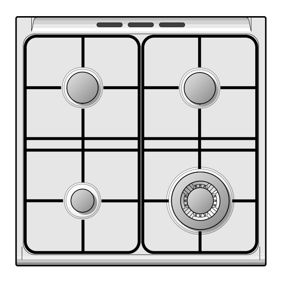
COOKING HOBS – Cookers – Cookers mod. 66 X 440 (inox) mod. 66 X 640 (inox) - 66 X 640 IS (inox) mod. 66 W 440 (white) mod. 66 W 640 (white) Fig. 1.3 Fig. 1.1 Fig. 1.2 – Cookers mod. -
Page 6: Control Panels
CONTROL PANELS mod. 66 X 640 (inox) - 66 W 640 (white)- 66 X 640 IS (inox) Fig. 2.1 15 14 mod. 66 X 630 (inox) - 66 W 630 (white) Fig. 2.2 15 14 mod. 66 X 130 (inox) - 66 W 130 (white) Fig. -
Page 7: Control Panel
CONTROL PANELS mod. 66 X 630 IS (inox) Fig. 2.5 mod. 66 X 330 IS (inox) Fig. 2.6 CONTROL PANEL - Pushbuttons: Controls description 14. Oven light switch 1. Front right burner control knob 15. Rotisserie switch 2. Rear right burner control knob 16. -
Page 8: Use Of Cooking Hob
USE OF COOKING HOB GAS BURNERS Each burner is controlled by a gas tap assuring the opening and the closing of the gas supply. Make the lever of the knob match with the indicator on the control panel to obtain: –... - Page 9 ELECTRIC SPARK IGNITION LIGHTING GAS BURNERS FITTED WITH SAFETY VALVE DEVICE Models with electronic ignition Models with electronic ignition pushbutton pushbutton To light the burner you have to rotate the knob (fig. 3.2) corresponding to the To the light the burners: specific burner to the maximum flame 1 –...
-
Page 10: Choice Of The Burner
LIGHTING GAS BURNERS FITTED CHOICE OF THE BURNER WITH SAFETY VALVE DEVICE On the control panel, near every knob, there is a diagram that indicates which Models with electric ignition burner is controlled by that knob. incorporated in the knob The suitable burner must be chosen To ignite the burner, the following according to the diameter and the... - Page 11 CORRECT USE OF TRIPLE-RING BURNER The flat-bottomed pans are to be placed directly onto the pan-support. To use the WOK you need to place the proper stand in order to avoid any faulty operation of the triple-ring burner (Figs. 3.5 - 3.6). WRONG CORRECT Fig.
-
Page 12: Electric Hotplate
PROPER USE OF THE ELECTRIC ELECTRIC HOTPLATE HOTPLATE (fig. 3.8) NORMAL HOTPLATE When the pan comes to the boil, turn the heat down to the level desired. To turn on the electric hotplate, rotate Remember that the hotplate will continue the knob to the desired setting. - Page 13 ELECTRIC HOTPLATE USAGE TABLE Position TYPE OF COOKING of switch Switched OFF For melting operations (butter, chocolate). To maintain food hot and to heat small quantities of liquid (sauces, eggs). To heat bigger quantities; to whip creams and sauces. (vegetables, fruits, soups). Slow boiling, i.e.: boiled meats, spaghetti, soups, continuations of steam,...
-
Page 14: General Features
GAS OVEN mod. 66 X 640 (inox) - 66 W 640 (white) mod. 66 X 630 (inox) - 66 W 630 (white) mod. 66 X 630 IS (inox) - 66 X 640 IS (inox) The glass on the oven door reaches high temperatures during operation. - Page 15 IGNITION OF THE OVEN BURNER Models with electric ignition incorporated in the knob ATTENTION: Never turn the thermostat 2) Lightly press and turn the thermostat before pressing the ignition button or knob anti-clockwise (fig. 4.2) to max before approaching a flame to the hole position “...
-
Page 16: Oven Cooking
THERMOSTAT OVEN COOKING Before introducing the food, preheat the The numbers 1 to 10 printed on the oven to the desired temperature. knob (fig. 4.1a - 4.1b) indicate the For a correct preheating operation, it is increasing oven temperature value (see advisable to remove the tray from the table 4.5). - Page 17 IGNITION OF THE GRILL BURNER Model with electric ignition incor- porated in the knob IMPORTANT: the oven door must be open during this operation. 2) Lightly press and turn the thermostat knob clockwise to the position 1 – Open the oven door to the full (fig.
-
Page 18: Use Of The Grill
USE OF THE GRILL OVEN LIGHT Very important: the grill must always The cooker is equipped with a light that be used with the oven door ajar (Fig. illuminates the oven to enable visually 4.10). controlling the food that is cooking. Mount shield “A”... - Page 19 ROTISSERIE (Fig. 4.13) This device is made up of: – an electrical motor mounted on the rear part of the oven – stainless steel spit with a removable stay-cool handle and two adjustable sets of prongs – spit support to be inserted in the central guide of the oven.
-
Page 20: Convection Oven
CONVECTION OVEN mod. 66 X 130 (inox) - 66 W 130 (white) ELECTRICAL THERMOSTAT 66 X 440 (inox) - 66 W 440 (white) Turn on the oven or grill elements by tur- ning the switch that is also provided with a The glass on the oven door thermostat to control the oven temperature. - Page 21 OVEN COOKING ELECTRICAL GRILL The grill element has got 2000 W input To cook, before introducing the food, and is controlled by the switch/thermo- preheat the oven to the desired tempera- stat by positioning the symbol of the ture. knob onto the control panel indicator. When the oven has reached the desired temperature, introduce the food, control USE OF THE GRILL...
- Page 22 ROTISSERIE OVEN LIGHT (Fig. 5.4) The oven is equipped with a light that The oven is equipped with a rotisserie for illuminates the oven to enable visually cooking on the spit using the grill. controlling the food that is cooking. This device is made up of: This light remains on during all cooking –...
-
Page 23: Multifunction Electric Oven
MULTIFUNCTION ELECTRIC OVEN mod. 66 X 330 IS (inox) OPERATING PRINCIPLES Heating and cooking in the MULTI- FUNCTION oven are obtained in the fol- Attention: the oven door becomes lowing ways: very hot during operation. Keep children away. a. by normal convection The heat is produced by the upper and lower heating elements. -
Page 24: Function Selector Knob
Fig. 6.1 Fig. 6.2 FUNCTION SELECTOR KNOB (Fig. 6.1) OVEN LIGHT Rotate the knob clockwise to set the oven for one of the following functions. By turning the knob onto this setting (see picture aside) we light the oven cavity. The oven remains alight while any of the THERMOSTAT KNOB functions is on. -
Page 25: Hot Air Cooking
HOT AIR COOKING GRILLING The infra-red heating element is switched The circular element and the fan are on. on. The heat is diffused by radiation. The heat is diffused by forced convec- Use with the oven door closed and tion and the temperature must be regu- the thermostat knob to position 225°C lated between 50°... -
Page 26: Cooking Advice
COOKING ADVICE MAINTAINING TEMPERATURE AFTER COOKING OR SLOWLY HEATING FOODS STERILIZATION The upper element and the circular ele- Sterilization of foods to be conserved, in ment connected in series, are switched full and hermetically sealed jars, is done on; also the fan is on. The heat is dif- in the following way: fused by forced convection with the a. - Page 27 SIMULTANEOUS COOKING OF GRILLING AND “AU GRATIN” DIFFERENT FOODS Grilling may be done without the roast- ing jack on position of the switch, The MULTI-FUNCTION oven set on because the hot air completely envelops position consents a simulta- the food that is to be cooked. neous heterogeneous cooking of differ- Set the thermostat to position 175 °C ent foods.
- Page 28 COOKING EXAMPLES OVEN COOKING Temperatures times Before introducing the food, preheat the approximate as they vary depending on oven to the desired temperature. the quality and amount of food. For a correct preheating operation, it is advisable to remove the tray from the Remember to use ovenproof dishes and oven and introduce it together with the to adjust the oven temperature during...
-
Page 29: Minute Counter
GENERAL ADVICE MINUTE COUNTER – When the appliance is not being used, it is advisable to keep the gas tap closed. MINUTE COUNTER (Fig. 7.1) – Every now and then check to make sure that the flexible tube that The minute counter is a timed acoustic connects the gas line or the gas warning device which can be set for a cylinder to the appliance is in perfect... -
Page 30: Cleaning And Maintenance
CLEANING AND MAINTENANCE REGULATING OF THE BALANCE THE LID MIGHT BREAK IF OVER- Lower the lid and check the correct bal- HEATED ance. While opened at 45° it should Do not close the cooker lid when hang up. the burners or electric plates are The springs of the hinges can be adjust- still hot and when the oven is on ed if necessary by turning the screws... - Page 31 BURNERS CORRECT REPLACEMENT OF THE BURNERS They can be removed and washed with soapy water only. It is very important to check that the They will remain always perfect if burner flame distributor F and the cap C cleaned with products used has been correctly positioned (see figs.
- Page 32 TRIPLE RING BURNER The triple ring burner must be correctly positioned (see fig. 8.3); the burner rib must be enter in their logement as shown by the arrow. Then position the cap A and the ring B (fig. 8.4 - 8.5). The burner correctly positioned must not rotate (fig.
-
Page 33: Replacing The Oven Light Bulb
GAS TAPS OVEN DOOR AND DRAWER In the event of operating faults in the gas The internal glass of the oven door can taps, call the Service Department. be easily removed for cleaning by unscrewing the two lateral fixing screws (fig. - Page 34 INSIDE OF OVEN Advice for use and maintenance of catalytic panels This must be cleaned every time it is used. The catalytic panels are covered with Remove and refit the side runner frames special microporous enamel which as described on the next chapter. absorbs and does away with oil and fat With the oven warm, wipe the inside splashes during normal baking over...
-
Page 35: Removing The Oven Door
Type A REMOVING THE OVEN DOOR To facilitate oven cleaning, it is possible to remove the door. Please follow the instructions carefully: – Open the door completely. – Push down the lever “L” and, keeping it in this position, slowly close the door in order to block the hinge. - Page 36 Type B Fig. 8.14A REMOVING THE OVEN DOOR The oven door can easily be removed as follows: – Open the door to the full extent (fig. 8.14A). – Attach the retaining rings to the hooks on the left and right hinges (fig. 8.14B). Fig.
-
Page 37: Installation
INSTALLATION Advice for the installer IMPORTANT – Cooker installation must only be carried out by QUALIFIED TECHNICIANS and in compliance with local safety standards. Failure to observe this rule will invalidate the warranty. The appliance must be installed in compliance with regulations in force in your country and in observation of the manufacturer's instructions. - Page 38 CHOOSING SUITABLE This appliance is not connected to a SURROUNDINGS device to evacuate the combustion products. This must be installed and In the room chosen to accommodate the connected in conformity with the gas appliance, there must be an ade- installation rules in force.
-
Page 39: Gas Section
GAS SECTION Before installation, make sure that The walls adjacent to the cooker the local distribution conditions must be of material resistant to heat. (type of gas and its pressure) and the adjustment of this appliance Cat: are compatible. The appliance adjustment conditions are given on The appliance is predisposed and the plate or the label. - Page 40 Use rigid or flexible connection pipes which comply with applicable regulations. If a flexible hose is used, make sure that it is pushed over the hose connector to the full depth, and secured with a hose clamp (not supplied). If compression fittings are used, tighten firmly using two spanners (fig.
- Page 41 Gas maintenance OPERATIONS TO BE EXECUTED FOR THE REPLACEMENT OF THE INJECTORS OF THE TOP BURNERS The injectors are avilable from the After- Sales Service. The diameter is marked on the injector in cents of millimetre. Select the injectors to be replaced according to the “Table for the choice of the injectors”...
- Page 42 TABLE FOR THE CHOICE OF THE INJECTORS Cat: G 30/G 31 Nominal Reduced 28-30/37 mbar power power Tube ring By-pass Ø injector BURNERS [kW] [kW] opening [mm] [1/100 mm] [1/100 mm] 1,00 0,30 – Auxiliary (A) 1,75 0,45 – Semirapid (SR) 3,50 1,50 –...
- Page 43 OPERATIONS TO BE EXECUTED FOR THE REPLACEMENT OF THE INJECTORS OF THE OVEN AND GRILL BURNERS a) oven burner – Lift and remove the lower panel inside the oven. – Remove the burner securing screw Fig. 10.6 (fig. 10.6) – Withdraw the burner as shown in fig- ure 10.7 and rest it inside the oven.
-
Page 44: Primary Air Of The Oven Burner
PRIMARY AIR OF THE OVEN PRIMARY AIR OF THE GRILL BURNER BURNER With a screwdriver untighten the two With a screwdriver untighten the screw screws (fig. 10.10) and move forward or (fig. 10.11) and turn the air ring to close backward to close or open the air flow, or open the air flow, according to the Air the air ring according to the Air... -
Page 45: Adjustment Of The Oven Burner Minimum
ADJUSTMENT OF THE OVEN BURNER MINIMUM This needs to be done only for the oven burner (the grill is a fixed capacity) by acting on the thermostat in the following way: – turn on the burner by setting the ther- mostat knob on position 10 –... -
Page 46: Lubrication Of The Gas Taps
LUBRICATION OF THE GAS TAPS Flame Flame Flame faulty in correct with excess The operations must be executed by a primary air primary air qualified technician. long, yellow clear short and sharp interior blue too blue interior trembling cone cone tending to detach CAUSE air regulating... -
Page 47: Electrical Section
ELECTRICAL SECTION N.B. For connection to the mains, do IMPORTANT: The cooker must be not use adapters, reducers or branch- installed in accordance with the man- ing devices as they can cause over- ufacturer’s instructions. heating and burning. Incorrect installation, for which the manufacturer accepts no responsibil- If the installation requires alterations to ity, may cause damage to persons,... - Page 48 CONNECTING THE NEW FEEDER – Connect the wires to the terminal block “B” as shown in the diagram in CABLE figure 11.3 - 11.4; or connect the phase wires to the terminal block To connect the feeder cable to the cook- “B”and the earth wire to the terminal er it is necessary to: PE as shown in figure 11.1 - 11.2.
- Page 49 FEEDER CABLE SECTION TYPE HO5RR-F mod. 66 X 640 (inox) - 66 W 640 (white) - 66 X 640 IS (inox) 230 V 3 x 0,75 mm (*) (**) mod. 66 X 630 (inox) - 66 W 630 (white) 66 X 630 IS (inox) 230 V 3 x 1 mm (*) (**)
- Page 52 The manufacturer cannot be held responsible for possible inaccuracies due to printing or transcrip- tion errors in the present booklet. The manufacturer reserves the right to make all modifications to its products deemed necessary for manufacture or commercial reasons at any moment and without prior notice, without jeopardising the essential functional and safety characteristics of the appliances.
Need help?
Do you have a question about the 6N Series and is the answer not in the manual?
Questions and answers