
Related Manuals for Elba Gas Cookers


Summary of Contents for Elba Gas Cookers
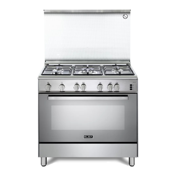
- Page 1 Instructions for the use - Installation advices GAS COOKERS ELBA QUALITY MADE IN ITALY H O M E A P P L I A N C E S Made in Italy...
-
Page 2: Dear Customer
Dear Customer, Thank you for having purchased and given your preference to our product. The safety precautions and recommendations reported below are for your own safety and that of others. They will also provide a means by which to make full use of the features offered by your appliance. -
Page 3: Important Safety Precautions And Recommendations
IMPORTANT SAFETY PRECAUTIONS AND RECOMMENDATIONS IMPORTANT: This appliance is designed and manufactured solely for the cooking of domestic (household) food and is not suitable for any non domestic application and therefore should not be used in a commercial environment. The appliance guarantee will be void if the appliance is used within a non domestic environment i.e. - Page 4 • Do not touch the appliance with wet or damp hands (or feet). • Do not use the appliance whilst in barefoot. • If you should decide not to use this appliance any longer (or decide to substitute another model), before disposing of it, it is recommended that it be made inoperative in an appropriate manner in accordance to health and environmental protection regulations, ensuring in particular that all potentially hazardous parts be made...
- Page 5 • WARNING: Danger of fire: do not store items on the cooking surfaces. • WARNING: When correctly installed, your product meets all safety requirements laid down for this type of product category. However special care should be taken around the rear or the underneath of the appliance as these areas are not designed or intended to be touched and may contain sharp or rough edges, that may cause injury.
-
Page 6: Cooking Hob
COOKING HOB Fig. 1.1 GAS BURNERS 1. Auxiliary burner (A) 1,00 kW 2. Semi-rapid burner (SR) 1,75 kW 3. Rapid burner (R) 3,00 kW 4. Triple-ring (TR) 3,50 kW CAUTION: Gas appliances produce heat and humidity in the environment in which they are installed. Ensure that the cooking area is well ventilated by opening the natural ventilation grilles or by installing an extractor hood connected to an outlet duct. -
Page 7: Control Panel
CONTROL PANEL Fig. 2.1 CONTROLS DESCRIPTION Gas oven/grill thermostat control knob 60’ alarm control knob Front left burner control knob Rear left burner control knob Central burner control knob Rear right burner control knob Front right burner control knob Pushbuttons Electric ignition Rotisserie 10. -
Page 8: Use Of The Hob Burners
USE OF THE HOB BURNERS GAS BURNERS Gas flow to the burners is adjusted by turning the knobs (illustrated in fig. 3.1) which control the safety valves. Turning the knob, so that the indicator line points to the symbols printed on the control panel, achieves the following functions: - symbol closed valve... -
Page 9: Lighting The Burners
LIGHTING THE BURNERS CHOICE OF THE BURNER ignite burner, following On the control panel, near every knob instructions are to be followed: there is a diagram that indicates which burner is controlled by that knob. Press in the corresponding knob and The suitable burner must be chosen turn counter-clockwise (fig. -
Page 10: General Features
USE OF THE GAS OVEN THERMOSTAT The glass on the oven door reaches The numbers 1 to 10 printed on the control high temperatures during operation. panel (fig. 4.1) indicate the increasing oven Keep children away. temperature value (see table 4.2). Models with glass lid: The cooker lid The temperature is kept constant on the must be kept open when the gas oven/... - Page 11 IGNITION OF THE OVEN BURNER If the flame extinguishes for any reason, the safety valve will automatically shut off ATTENTION: Never turn the control the gas supply to the burner. knob before opening the oven door. To re-light the burner, first turn the oven control knob to position “0”...
-
Page 12: Oven Cooking
COOKING EXAMPLES For efficient oven preheating, we Temperatures are approximate as they recommend that grill trays and racks vary depending on the quality and amount are removed from the oven and of food. replaced after about 15 minutes. Remember to use ovenproof dishes and to adjust the oven temperature during cooking if necessary. - Page 13 IGNITION OF THE GRILL BURNER The grill must always be used with the oven door slightly open and ATTENTION: Never turn the control with shield “A” mounted (Fig. 4.9). knob before opening the oven door. See specific instructions in the section ‘USE OF THE GRILL’. To ignite the grill burner: Open the oven door to the full extent.
- Page 14 USE OF THE GRILL OVEN LIGHT The cooker is equipped with a light that Very important: The grill must always be illuminates the oven to enable visually used with the oven door slightly open controlling the food that is cooking. and with shield “A” mounted (Fig. 4.9).
- Page 15 USE OF THE ROTISSERIE ROTISSERIE (Fig. 4.12) This is used for spit roasting under the grill • Insert the tray into the lowest rack and comprises: holders of the oven and insert the • an electric motor fitted to the rear of rod support into the intermediate rack the oven;...
-
Page 16: Minute Counter
60’ ALARM MINUTE COUNTER The minute counter is a timed acoustic warning device which can be set for a maximum of 60 minutes. The knob (Fig. 5.1) must be rotated clockwise as far as the 60 minute position and then set to the required time by rotating it anticlockwise. -
Page 17: Cleaning And Maintenance
CLEANING AND MAINTENANCE MODELS WITH GLASS LID ONLY For cleaning purposes, the lid can be easily Models with glass lid removed upwards once taken to the upright position. Should the hinges slip off, replace them in their housing being careful that: •... -
Page 18: General Advice
GENERAL ADVICE ENAMELLED PARTS • Before you begin cleaning, you All the enamelled parts must be cleaned must ensure that the appliance is with a sponge and soapy water or other switched off. non-abrasive products. Dry preferably with a microfibre or soft •... - Page 19 GAS TAPS BURNERS AND PAN SUPPORTS Periodic lubrication of the gas taps must be These parts can be removed and cleaned carried out by specialist personnel only. with appropriate products. In the event of operating faults in the gas After cleaning, the burners and their flame taps, call the Service Department.
- Page 20 Fig. 6.2 Fig. 6.3 Fig. 6.4 Fig. 6.5 Fig. 6.6...
-
Page 21: Oven Floor
INSIDE OF OVEN Fig. 6.7 The oven should always be cleaned after use when it has cooled down. The cavity should be cleaned using a mild detergent solution and warm water. Suitable proprietary chemical cleaners may be used after first consulting with the manufacturers recommendations and testing a small sample of the oven cavity. -
Page 22: Storage Compartment
OVEN DOOR STORAGE COMPARTMENT The internal glass panel can be easily The storage compartment is accessible removed for cleaning by unscrewing the 4 through the pivoting panel (fig. 6.11). retaining screws (fig. 6.10). Do not use harsh abrasive cleaners or sharp metal scrapers to clean the oven Do not store flammable material in the door glass since they can scratch the... -
Page 23: Removing The Oven Door
REMOVING THE OVEN DOOR The oven door can easily be removed as follows: • Open the door to the full extent (fig. 6.12a). • Open the lever “A” completely on the left and right hinges (fig. 6.12b). • Hold the door as shown in fig. 6.12. •... - Page 24 Advice for the installer IMPORTANT • Cooker installation must only be carried out by QUALIFIED TECHNICIANS and in compliance with local safety standards. The appliance must be installed in compliance with regulations in force in your country and in observation of the manufacturer’s instructions.
-
Page 25: Installation
INSTALLATION The installation conditions, concerning protection against overheating of the surfaces adjacent to the cooker, must conform to Figs. 7.1a or 7.1b. The cooker must be kept no less than 200 mm away from any side wall which exceed the height of the cooktop. -
Page 26: Fitting The Adjustable Feet
FITTING THE ADJUSTABLE FEET The adjustable feet must be fitted to the base of the cooker before use (fig. 7.2). Rest the rear of the cooker on a piece of the polystyrene packaging exposing the base for the fitting of the feet. Fit the 4 legs by screwing them tight into the support base as shown in figure 7.3. -
Page 27: Moving The Cooker
MOVING THE COOKER WARNING: When raising cooker to upright position always ensure two people carry out this manoeuvre to prevent damage to the adjustable feet (fig. 7.6). Fig. 7.6 WARNING WARNING Be carefull: do not lift the cooker by the When moving cooker to its final position door handle when raising to the upright DO NOT DRAG (fig. 7.8). position (fig. 7.7). Lift feet clear of floor (fig. 7.6). Fig. -
Page 28: Ventilation Requirements
VENTILATION REQUIREMENTS The appliance must be installed in compliance with applicable local regulations concerning ventilation and the evacuation of exhaust gases. Intensive and prolonged use may require extra ventilation, e.g. opening a window, or more efficient ventilation increasing the mechanical suction power if this is fitted. CHOOSING SUITABLE SURROUNDINGS The room where the gas appliance is to be installed must have a natural flow of air so that the gas can burn (in compliance with applicable local regulations). -
Page 29: Gas Section
GAS SECTION GAS INSTALLATION REQUIREMENTS Important ! • The walls adjacent to the cooker must be of heat-resistant material. Before installation, make sure that the local distribution conditions (gas type and • pressure) and the adjustment of this appliance are compatible. The appliance adjustment conditions are given on the plate or the label. - Page 30 Plug plug Fig. 8.1a Fitting the plug on the unused terminal of the gas inlet pipe Right or left inlet pipe Manifold male pipe fitting 1/2” G cylindrical (ISO 228-1) male Sealing washer (#) 1/2” G cylindrical (ISO 228-1) female Plug (#) (#) Already fitted on the right or left inlet pipe...
- Page 31 GAS CONNECTION WITH A RUBBER HOSE Imporant! A rubber hose connection shall only be made if permitted by the applicable local regulations. The gas connection is made up of: • the terminal fitting of the inlet pipe (right-hand or left-hand); •...
- Page 32 • you inform the customer that the gas cylinder valve or the gas supply valve immediately by the cooker should be closed when the cooker is not in use. • you inform the customer that the hose should not be subjected to corrosion by acidic cleaning agents.
- Page 33 GAS CONNECTION WITH RIGID PIPES OR A FLEXIBLE PIPE The gas connection is made up of: • the terminal fitting of the inlet pipe (right-hand or left-hand) • sealing washer. Important! If fitted, remove the hose holder from the terminal fitting of the inlet pipe. When connecting the cooker to the gas supply with rigid pipes or a flexible pipe, make sure that •...
- Page 34 Gas connection with rigid or flexible pipe Note: if already fitted on the inlet pipe, remove the rubber hose holder Inlet pipe Manifold male 1/2” G cylindrical pipe fitting (ISO 228-1) male Sealing washer (#) (#) If not already fitted on the inlet pipe, it is supplied with the appliance in a separate kit 1/2”...
-
Page 35: Lubrication Of The Gas Taps
GAS MAINTENANCE TABLE FOR THE CHOICE OF THE INJECTORS - Cat: 2H 3+ Natural gas G30 (28-30 mbar) G20 (20 mbar) Nominal Reduced G31 (37 mbar) BURNERS power power Ring Ring [kW] [kW] Ø injector Ø injector opening opening [1/100 mm] [1/100 mm] [mm] [mm]... -
Page 36: Replacement Of The Burner Injectors
REPLACEMENT OF THE BURNER A u x i l i a r y, INJECTORS Semi-rapid and Rapid Select the injectors to be replaced burners according to the “Table for the choice of the injectors”. If the injectors are not supplied they can be obtained from the “Service Centre”. - Page 37 OPERATIONS TO BE EXECUTED FOR THE REPLACEMENT OF THE INJECTORS OF THE OVEN AND GRILL BURNER a) oven burner • Lift and remove the lower panel inside the oven. • Unscrew and remove the burner securing screw “A” (fig. 8.7). •...
- Page 38 b) grill burner • Unscrew and remove the burner securing screw “C” (fig. 8.9). • Slacken screw “D” (fig. 8.9). • Move the burner in the manner shown in figure 8.10. Take care not to damage the wire to the ignition electrode and the safety valve probe.
- Page 39 Fig. 8.11 REGULATION OF AIR SUPPLY TO OVEN AND GRILL BURNERS Using a cross-head screwdriver, slacken the screw “Q” securing the air flow regulation collar “P” (fig. 8.11 and 8.12) and turn the collar forward or backward to increase or reduce the air aperture in accordance with gas type and the indications in the “Table for the choice of the injectors”.
- Page 40 ADJUSTMENT OVEN Flame faulty Flame with Flame BURNER MINIMUM in primary excess correct primary air This needs to be done only for the oven burner (the grill is a fixed capacity) by short and sharp long, yellow clear interior too blue interior acting on the thermostat.
-
Page 41: Electrical Section
ELECTRICAL SECTION N.B. For connection to the mains, do IMPORTANT: The cooker must be not use adapters, reducers or branching installed accordance with devices as they can cause overheating manufacturer’s instructions. and burning. Incorrect installation, which If the installation requires alterations to the manufacturer accepts domestic electrical system or if the socket... - Page 42 ELECTRICAL FEEDER CABLE FEEDER CABLE SPECIFICATIONS CONNECTION TYPE H05RR-F To connect the supply cable: 230 or 220-240 V~ 3 x 0,75 mm (*) (**) • Remove the screw securing the cover “A” on the rear of the cooker (fig. 9.1). Connection possible with plug and outlet •...
- Page 44 The manufacturer reserves the right to make all modifications to its products deemed necessary for manufacturer commercial reasons at any moment and without prior notice, without jeopardising the essential functional and safety characteristics of the appliances. www.elba-cookers.it H O M E A P P L I A N C E S Made in Italy...
Need help?
Do you have a question about the Gas Cookers and is the answer not in the manual?
Questions and answers