Table of Contents
Advertisement
Quick Links
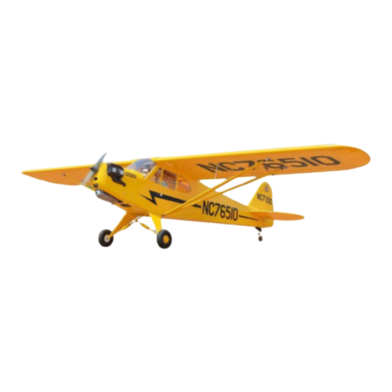
PIPER J-3 CUB
Glow and EP
ALL BALSA - PLY WOOD CONSTRUCTION.
COVERED WITH ORACOVER
95% ALMOST READY TO FLY
SPECIFICATION:
- Wingspan:1,950 mm (76.77in).
- Length: 1,297 mm (51.06 in).
- Weight: 3.2 - 3.5 kg (7.04 - 7.7 lbs).
- Wing area: 53.8 dm
.
2
- Wing loading: 59.5 g/dm
- Wing type: USA - 35B.
- Servo mount: 42mm x 21mm.
- Gear type: Aluminium Hi-grade for main gear
and spring wire for tail gear (included).
Parts listing required (not included):
- Radio : 04 channels.
- Servo : 05 - 06 servos.
- Engine: NGH GT-9, 9cc gas motor
- Motor: Brushless outrunner 1000-1800W, 400-800KV.
- Propeller: Suit with your engine.
Instruction Manual Book
R
.
2
Item code: BH04
Recommended Motor and Battery set up
(not included):
- Motor: Admiral GP10 5030-400kV
- Lipo cell: 6 cells 4,000-5,000mAh.
- Receiver battery: 4.8- 6V/ 800 - 1200mAh NiMH.
- ESC: 65A
Made in Vietnam.
Advertisement
Table of Contents

Subscribe to Our Youtube Channel
Related Manuals for Black Horse Model Motion RC PIPER J-3 CUB


Summary of Contents for Black Horse Model Motion RC PIPER J-3 CUB
- Page 1 Instruction Manual Book Item code: BH04 PIPER J-3 CUB Glow and EP ALL BALSA - PLY WOOD CONSTRUCTION. COVERED WITH ORACOVER 95% ALMOST READY TO FLY SPECIFICATION: Recommended Motor and Battery set up - Wingspan:1,950 mm (76.77in). (not included): - Length: 1,297 mm (51.06 in). - Motor: Admiral GP10 5030-400kV - Weight: 3.2 - 3.5 kg (7.04 - 7.7 lbs).
-
Page 2: Table Of Contents
Thank you for purchasing Black Horse Model products. With over 18 years experience in production and fly testing, Black Horse Model is committed to bring the best quality products and good service to customers. Along with a team of creative engineers and skilled workers, we will always accompany with customers by our great experiences, fully enthusiasm... -
Page 3: Warranty
Please strictly follow the instruction manual to assemble work area thoroughly after working with berglass parts. and use this. In that Black Horse Model has no control over the nal SUGGESTION assembly or material used for nal assembly, Black Horse Model is not responsible for loss of use , or other incidental or consequential damages. -
Page 4: Covering Tools
Instruction manual PIPER J-3 CUB Item code: BH04 ADHESIVES AND REQUIRED TOOLS FLIGHT WARNINGS When ready to y, rst extend the transmitter aerial. Thin CA Switch on the transmitter. 30-minute epoxy Switch on the receiver. 6-minute epoxy Check that the wings are correctly tted to the fuselage. Threadlocker thread locking cement Operate the control sticks on the transmitter and check Mixing sticks... - Page 5 Instruction manual PIPER J-3 CUB Item code: BH04 • Officially designated AMA Air Show Teams (AST) are authorized to use devices and practices as defined within the Team AMA Program Document. (AMA Document #718.) (j) Not operate a turbine-powered aircraft, unless in compliance with the AMA turbine regulations. (AMA Document #510-A.) 3.
-
Page 6: Parts Listing (Not Included)
Instruction manual PIPER J-3 CUB Item code: BH04 PARTS LISTING (NOT INCLUDED) Motor: Admiral GP10 ..1 pcs. Engine: 9cc..1 pcs. Servos size: (39.9 x 20.1 x 38.1)mm. Torque servos: 3.17kg/cm - 4.10kg/cm ..5 pcs ESC: 65A ..1 pcs. Suit with your engine. - Page 7 Instruction manual PIPER J-3 CUB Item code: BH04 : Fuselage. : Wing panel ( 2a, 2b ). : Horizontal stabilizer. : Vertical stabilizer. : Aluminium wing dihedral brace. : Decal sheet. : Cockpit fuselage ( 7a: Canopy, 7b: Pilot). : Fuel tank ( 8a: Clunk, 8b: Stopper (three line)). : Plastic parts for cowling ( 9a, 9b ).
-
Page 8: Preparations
Instruction manual PIPER J-3 CUB Item code: BH04 PREPARATIONS: Use a covering iron with a covering sock on hign heat to tighten the covering if necessary. Apply pressure over sheeted areas to thoroughly bond the covering to the wood INSTALLING THE AILERONS Bottom view 2) Apply drops of thin CA to the top and bottom of each hinge. - Page 9 Instruction manual PIPER J-3 CUB Item code: BH04 Place the servo into the servo tray/ hatch into the Repeat step # 2 - # 5 to install the second aileron servo box on the bottom of the wing and drill 1.5mm servo in the opposite wing half.
-
Page 10: Installing The Control Horns And Linkages
Instruction manual PIPER J-3 CUB Item code: BH04 Bottom view INSTALLING THE CONTROL HORNS AND LINKAGES - - - 2 Nylon Clevis - - - 2 100mm Push rod - - 2 Horn Flaslink - - - - - - 2 Horn - - - - - - 2 Bottom view... - Page 11 Instruction manual PIPER J-3 CUB Item code: BH04 Control Horn Servo arm Push rod Flaslink Mark the spot to attach Bend 90 Bottom view...
-
Page 12: Installing The Fuselage Servos
Instruction manual PIPER J-3 CUB Item code: BH04 INSTALLING THE FUSELAGE SERVOS Install the rubber grommets and brass collets into the elevator, rudder and throttle servos. Test fit the servos into the servo tray. Trim the tray if necessary to fit your servos. -
Page 13: Installing Horizontal Stabilizer
Instruction manual PIPER J-3 CUB Item code: BH04 INSTALLING HORIZONTAL STABILIZER Then put the horizontal into the fuselage. Check the fit of the horizontal stabilizer in its slot. Draw a center line Using a modeling knife, carefully remove the film covering from the tail slots at the rear of the fuselage. -
Page 14: Installing The Control Horns And Linkages
Instruction manual PIPER J-3 CUB Item code: BH04 INSTALLING THE CONTROL HORNS AND LINKAGES Flaslink Nylon Clevis 900mm Push rod Horn - - - - - - 1 - - - 2 - - 2 Duo rod connection lock - - - - - - 2 100mm Push rod - - - - - - 1 - - - 2... - Page 15 Instruction manual PIPER J-3 CUB Item code: BH04 Servo arm Flaslink Push rod Bend 90 Elevator servo Elevator pushrod Flaslink SetScrew Horn Fuselage top side Elevator servo Elevator pushrod Flaslink Cut off excess.
-
Page 16: Installing The Vertical Stabilizer
Instruction manual PIPER J-3 CUB Item code: BH04 INSTALLATION THE VERTICAL STABILIZER Hinges for Rudder are glued the same way as the aileron before (see page 8) Rudder Top side. INSTALLING THE CONTROL HORNS AND LINKAGES Control horn and linkages for Rudder are installed the same way as the elevator before (see page 13, 14). Nylon Clevis - - - 1 - - - 2... -
Page 17: Installing The Tail Gear
Instruction manual PIPER J-3 CUB Item code: BH04 Rudder pushrod Flaslink Rudder servo Flaslink Rudder pushrod Rudder servo INSTALLING THE TAIL GEAR tail wheel 3x12mm Tp Screw 3mm Collar assembly in place on the - - - - - - - 2 plywood plate. - Page 18 Instruction manual PIPER J-3 CUB Item code: BH04 Using the knife cut away the wood from the Mark the locations of the two mounting screws. bottom of the rudder and slide the two nylon Remove the t ail wheel bracket and drill 2.5mm pilot clasps into the slot.
-
Page 19: Installing The Engine
Instruction manual PIPER J-3 CUB Item code: BH04 INSTALLING THE ENGINE * Locate the long piece of wire used 3mm Hex Nut 500mm Pushrod wire for the throttle pushrod. One end of - - - 1 - - - - - - - 4 the wire has been pre-bend in to a 4x25mm Cap Screw Size: 46... -
Page 20: Installing The Installing The Stopper
Instruction manual PIPER J-3 CUB Item code: BH04 115mm INSTALLING THE STOPPER... -
Page 21: Installing The Fuel Tank
Instruction manual PIPER J-3 CUB Item code: BH04 Cut off shaded portion INSTALLING THE FUEL TANK 5. When satisfied with the alignment of the stopper assembly tighten the 3mm x 20mm machine screw until the rubber stopper expands and 1. Using a modeling knife, cut one length of silicon seals the tank opening. - Page 22 Instruction manual PIPER J-3 CUB Item code: BH04 Clunks - - - - - - - - - - 1 - - - - - - - - - - 1 Fuel Tank - - - - 1 TOP SIDE TOP SIDE Fuel tank...
-
Page 23: Installing The Throttle
Instruction manual PIPER J-3 CUB Item code: BH04 INSTALLING THE THROTTLE direction. When the throttle stick is moved forward from idle to full throttle, the throttle barrel should also open and close using this motion. If not, - - - - - - 1 Connector reverse the direction of the servo, using the transmitter. -
Page 24: Installing The Cowling
Instruction manual PIPER J-3 CUB Item code: BH04 MOUNTING THE COWL While holding the cowl firmly in position, Remove the mufler and needle valve assembly drill four 1,6mm pilot holes through both the from the engine. Slide the fiberglass cowl over the cowl and the side edges of the firewall. - Page 25 Instruction manual PIPER J-3 CUB Item code: BH04 3x12mm Tp Screw - - - 4 Fuselage Bottom side 3x12mm Tp Screw 3x12mm Tp Screw...
-
Page 26: Installing The Main Gear
Instruction manual PIPER J-3 CUB Item code: BH04 INSTALLING MAIN GEAR 4x15mm Cap Screw - - - - - - - - 6 4mm Flat Washer - - - - - - - - - 6 100mm Wheels 4mm Spring Washer - - - - - - - - - 6 5x45mm Socket Head Cap Screw... -
Page 27: Installing The Receiver And Battery
Instruction manual PIPER J-3 CUB Item code: BH04 Fuselage Bottom side C . A Apply instant glue (C.A glue, super glue). INSTALLING THE SWITCH, RECEIVER AND BATTERY INSTALLING THE SWITCH 1) Plug the servo leads and the switch lead into the receiver. -
Page 28: Installing The Electric Motor (Ep Version)
Instruction manual PIPER J-3 CUB Item code: BH04 Switch Switch Battery Receiver Zip tie Must be purchased separately! INSTALLING THE ELECTRIC MOTOR (EP VERSION) 4x60mm Socket Head 6x20mm M3 Blind Nut Cap Screw - - - - - 4 - - 4 3x15mm Cap Screw 10x40mm Plastic - - - - - 4... - Page 29 Instruction manual PIPER J-3 CUB Item code: BH04 M3 Blind Nut 3mm Spring Washer 3x15mm Cap Screw Motor: GP10 5030-400KV 4mm Flat washer 10x40mm Plastic 4mm Flat Washer 4mm Spring Washer 4x60mm Socket Head Cap Screw B a t t e r y...
-
Page 30: Installing The Cockpit Fuselage
Instruction manual PIPER J-3 CUB Item code: BH04 Battery 6x20mm Screw 6x20mm INSTALLING COCKPIT FUSELAGE TOP SIDE... - Page 31 Instruction manual PIPER J-3 CUB Item code: BH04 TOP SIDE Adhesive tape. Right Window Open/Close...
-
Page 32: Installing Balsa Plywood Wing Struts
Instruction manual PIPER J-3 CUB Item code: BH04 INSTALLING BALSA PLYWOOD WING STRUTS Machined Strut 3x6mm Button Head 3x12mm Cap Screw Ball link - - - - 4 Attachment Cap Screw - - - - - 8 - - - 14 3x15mm Tp Screw 3mm Spring Washer - - - - - - 4... - Page 33 Instruction manual PIPER J-3 CUB Item code: BH04 3x6mm Button Head 2.5mm Cap Screw 3x6mm Button Head 2.5mm Cap Screw 3x6mm Button 2.5mm Head Cap Screw 2.5mm 3x6mm Button Head Cap Screw Assemble left and right Apply epoxy glue. sides the same way. The number of times Drill holes using the stated.
- Page 34 Instruction manual PIPER J-3 CUB Item code: BH04 3x12mm Cap scew 3mm Spring Washer Ball link 3x12mm Cap scew BOTTOM SIDE Fuselage Bottom side 3x15mm Tp Screw The number of times the same way Assembly (in this case twice). Assemble left and right sides the same way.
-
Page 35: Installing The Wing To The Fuselage
Instruction manual PIPER J-3 CUB Item code: BH04 INSTALLING THE WING TO THE FUSELAGE Attach the aluminium tube into the fuselage. Locate the aluminium wing dihedral brace. 12mm Aluminium tube. 665mm *** Test fit the aluminium tube dihedral brace into each wing haft. The brace should slide in easily. -
Page 36: Installing The Propeller
Instruction manual PIPER J-3 CUB Item code: BH04 Screw the wing panel in position. Secure Propeller Must be purchased separately! -
Page 37: Balancing
Instruction manual PIPER J-3 CUB Item code: BH04 BALANCING 2) If one side of the wing fall, that side is heavier than the opposite. Add small amounts of lead weight to the bottom side of the lighter wing half's 1) It is critical that your airplane be balanced wing tip. -
Page 38: For Your Radio Installation Basic Connection For Airplane And Adjustment Of Servos
Instruction manual PIPER J-3 CUB Item code: BH04 FOR YOUR RADIO INSTALLATION BASIC CONNECTION FOR AIRPLANE AND ADJUSTMENT OF SERVOS For more information, refer to radio system instruction manual. Example of connection Follow instruction manual of Engine and Battery. Engine Aileron Servo Aileron Throttle Servo... -
Page 39: Decoration
Instruction manual PIPER J-3 CUB Item code: BH04 DECORATION Top view Bottom view < Side view > Left < Side view > Right ORACCOVER #21 - 030 - Cub Yellow... -
Page 40: Exploded View
Instruction manual PIPER J-3 CUB Item code: BH04... -
Page 41: I/C Flying Warning
I/C FLYING WARNINGS Always operate in open areas, away from NEVER fly near power lines, aerials or ALWAYS adjust the engine from behind factories, hospitals, schools, buildings and houses etc. NEVER fly your aircraft other dangerous areas including airports, the propeller, and do not allow any part of close to people or built up areas. -
Page 42: I/C Flying Guide
I/C FLYING GUIDELINES Operate the control sticks on the ALWAYS land the model INTO When ready to fly, first extend transmitter and check that the the wind, this ensures that the the transmitter aerial. control surfaces move freely and in model lands at the slowest possible the CORRECT directions.
Need help?
Do you have a question about the Motion RC PIPER J-3 CUB and is the answer not in the manual?
Questions and answers