Table of Contents
Advertisement
Quick Links
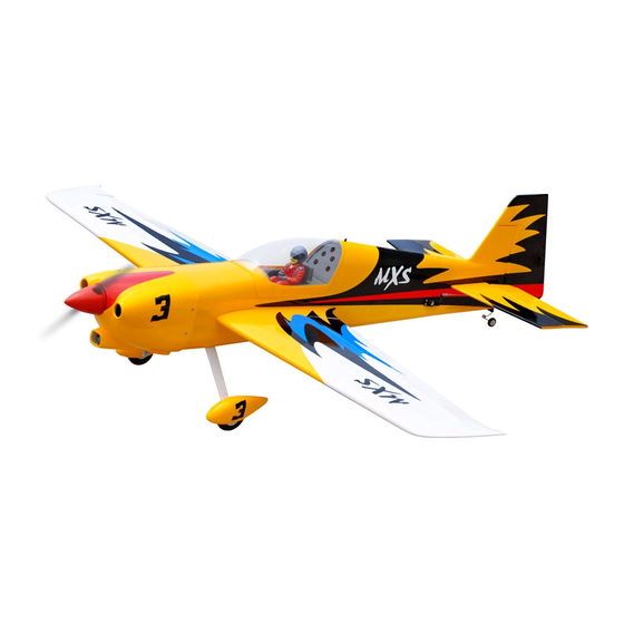
Instruction Manual Book
ALL BALSA - PLY WOOD CONSTRUCTION.
COVERED WITH ORACOVER
95% ALMOST READY TO FLY
SPECIFICATION:
- Wingspan: 1,620 mm (63.78 in).
- Length: 1,520 mm (59.84 in).
- Weight: 3.8 - 4 kg (8.36 - 8.8 lbs).
- Wing area: 43.15 dm .
- Wing loading: 88.06 g/dm .
- Wing type: Naca Airfoil.
- Servo mount: 42mm x 21mm.
- Gear type: Aluminium Hi-grade for main gear
and spring wire for tail gear (included).
- Spinner: 70mm.
Parts listing required (not included):
MXS
2
2
Item code: BH167.
- Radio: 05 channels.
- Servo: 06 standard high torque servos.
- Engine: 75 - 95 2 stroke ; 15 cc gas.
- Motor: Brushless outrunner 1200-2200W, 650KV.
- Propeller: Suit with your engine.
Recommended Motor
and Battery set up (not included):
- Motor: RIMFIRE.60.
- Lipo cell: 6 cells 4,000-5,000mAh.
- Receiver battery: 4.8 - 6V/ 800 -1200mAh NiMH.
- ESC: 80A.
Glow and EP
Made in Vietnam.
Advertisement
Table of Contents

Subscribe to Our Youtube Channel
Related Manuals for Black Horse Model BH167


Summary of Contents for Black Horse Model BH167
- Page 1 Instruction Manual Book Item code: BH167. Glow and EP ALL BALSA - PLY WOOD CONSTRUCTION. COVERED WITH ORACOVER 95% ALMOST READY TO FLY SPECIFICATION: - Wingspan: 1,620 mm (63.78 in). - Radio: 05 channels. - Length: 1,520 mm (59.84 in).
-
Page 2: Table Of Contents
Item code: BH167 TABLE OF CONTENTS Warning ......2 Installing the fuel tank ....11 Warranty . -
Page 3: Warranty
Caution! do not heat the film more than is In that Black Horse Model has no control over the absolutely necessary. If the air or the iron is too hot, the final assembly or material used for final assembly, black Horse Model is not responsible for loss of use, film may melt and holes may be formed. -
Page 4: Parts Listing (Not Included)
Item code: BH167 PARTS LISTING (NOT INCLUDED). Propeller Suit with your engine. Engine: 75..1 pcs. Servo extension leads....pcs. 500mm ..pcs. 190mm ..2 pcs. Size: 60 ..1 pcs. MOTOR ESC: 80A ..1 pcs. 6 cells 4,000-5,000mAh. - Page 5 Item code: BH167 : Fuselage. : Wing panel ( 2a, 2b . : Horizontal stabilizer. : Rudder. : Aluminium wing dihedral brace. : Cowling. : Spinner. : Cockpit fuselage (8a: Canopy, 8b : Pilot, c: Top hatch fuselage.). : Decal sheet.
-
Page 6: Preparations
Item code: BH167 PREPARATIONS: Use a covering iron with a covering sock on hign heat to tighten the covering if necessary. Apply pressure over sheeted areas to thoroughly bond the covering to the wood. INSTALLING THE AILERONS Bottom view 2) Apply drops of thin CA to the top and bottom of each hinge. - Page 7 Item code: BH167 For Aileron servo. 5. Place the servo into the servo tray/ hatch into the servo box on the bottom of the wing and drill 1.5mm pilot holes through the tray and servo box for each of the four mounting screws. Secure the servo tray in place using the mounting screws provided.
-
Page 8: Installing The Control Horns And Linkages
Item code: BH167 Bottom view INSTALLING THE CONTROL HORNS AND LINKAGES. - - - 2 2mm Nut - - - - - - Horn 100mm Push rod - - 2 Flaslink - - - - - - 2 Horn - - - - - - 2... - Page 9 Item code: BH167 Silicone tube Mark the spot to attach Bend 90 Silicone Tube 2mm Nut Push rod Push rod Flaslink Servo arm Bottom view...
-
Page 10: Installing The Engine Mount
Item code: BH167 INSTALLING THE ENGINE MOUNT OPTION 1: INSTALLING THE ELECTRIC MOTOR 5x10mm Aluminum 4x70mm Cap Screw - - - - - 4 - - 3 10x50mm Aluminum 4x20mm Cap Screw - - - - - 3 - - -... -
Page 11: Installing The Engine
Item code: BH167 OPTION 2: ENGINE INSTALLATION Installing the engine mount, fuel tank INSTALLING THE FUEL TANK. The stopper has been pre-assembled at the 7) Using a modeling knife, cut 3 lengths of fuel line. Connect 2 lines to the 2 vent tubes and 1 line to the factory. - Page 12 Item code: BH167 INSTALLING THE ENGINE. 500mm Pushrod wire - - 8 mm Nut - - - 1 4x30mm Cap Screw Connector - - - 1 - - - - - 8 4mm Washer Engine - - - - - - - 4...
-
Page 13: Installing The Throttle
Item code: BH167 2) Plug the throttle servo into the receiver and turn INSTALLING THE THROTTLE on the radio system. Check to ensure that the throttle servo output shaft is moving in the correct direction. When the throttle stick is moved forward... -
Page 14: Mounting The Cowl
Item code: BH167 MOUNTING THE COWL 1) Remove the muf f ler and needle valve assembly 4) While holding the cowl firmly in position, drill from the engine. Slide the fiberglass cowl over the four 1,6mm pilot holes through both the cowl and engine. -
Page 15: Installing Horizontal Stabilizer
Item code: BH167 INSTALLING HORIZONTAL STABILIZER Check to mark sure the wing and stabilizer are Draw a center line paralell. If they are not, lightly sand the opening in the fuselage for the stabilizer until the stabilizer is paralell to the wing, but don't glue anything yet. - Page 16 Item code: BH167 INSTALLING THE HORIZONTAL STABILIZER SERVOS Fuselage bottom side. Elevator servos approx.16mm Elevator servo Elevator servo...
- Page 17 Item code: BH167 INSTALLING THE CONTROL HORNS AND LINKAGES. - - - 4 3mm Nut - - - - - - 150mm Push rod - - 2 3mm Nut Horn - - - - - - 2 Push rod Horn Horn 2.5mm...
-
Page 18: Rudder Installation
Item code: BH167 Hinges and servo for Rudder are RUDDER INSTALLATION glued the same way as the aileron before (see page 6, 7). - - - 4 3mm Nut - - - - - - Horn 950mm Cable - - 2... - Page 19 Item code: BH167 Rudder servo Rudder cable Control horn Silicone Tube Rudder servo...
-
Page 20: Installing The Tail Gear
Item code: BH167 INSTALLING THE TAIL GEAR Mark the locations of the two mounting Set the tail wheel assembly in 3x12mm Screw screws. Remove the tail wheel bracket and place on the plywood plate. The - - - 2 drill 2.5mm pilot holes at the locations marked. -
Page 21: Installing The Main Gear
Item code: BH167 INSTALLING THE MAIN GEAR 4x15mm Cap Screw 5mm Washer - - - - - - - 4 - - - - - 4 Threadlocker 3mm Colar 5mm Nut 4mm Washer 5x45mm - - - - - 4... -
Page 22: Installing The Switch, Receiver And Battery
Item code: BH167 Secure INSTALLING THE SWITCH, RECEIVER AND BATTERY 1) Cut out the switch hole using a modeling knife. 4) Wrap the receiver and battery pack in the Use a 2mm drill bit and drill out the two mounting protective foam to protect them from vibration. -
Page 23: Secure The Wing To The Fuselage
Item code: BH167 Switch Fuselage top side SECURE THE WING TO THE FUSELAGE Locate the aluminium wing dihedral brace. *** Test fit the aluminium tube dihedral brace into each wing haft. The brace should slide in easily. If 19mm not, use 220 grit sand around the edges and ends of Aluminium tube. - Page 24 Item code: BH167 Insert the wing panel as pictures below. Screw the wing panel in position. Secure Secure Secure...
-
Page 25: Installing Cockpit Fuselage
Item code: BH167 Position the canopy so the rear frame on the INSTALLING COCKPIT FUSELAGE canopy is aligned with the rear edge of the cockpit opening. Use canopy glue to secure the canopy to the canopy hatch. Use low-tack tape to hold the canopy in position until the glue fully cures. -
Page 26: 15. Installing The Spinner, Propeller
Item code: BH167 15. INSTALLING THE SPINNER, PROPELLER - - - 2 Secure... -
Page 27: Balancing
Item code: BH167 2) If one side of the wing fall, that side is heavier BALANCING than the opposite. Add small amounts of lead weight to the bottom side of the lighter wing half's 1) It is critical that your airplane be balanced wing tip. -
Page 28: For Your Radio Installation Basic Connection For Airplane And Adjustment Of Servos
Item code: BH167 FOR YOUR RADIO INSTALLATION BASIC CONNECTION FOR AIRPLANE AND ADJUSTMENT OF SERVOS Example of connection For more information, refer to radio system instruction manual. Follow instruction manual of Engine and Battery. Engine Throttle Servo Aileron Servo Aileron... - Page 29 I/C FLINGT GUIDELINES Operate the control sticks on the ALWAYS land the model INTO When ready to fly, first extend transmitter and check that the the wind, this ensures that the the transmitter aerial. control surfaces move freely and in model lands at the slowest possible the CORRECT directions.
- Page 30 I/C FLINGT WARNINGS Always operate in open areas, away from NEVER fly near power lines,aerials or ALWAYS adjust the engine from behind factories, hospitals, schools, buildings the propeller, and do not allow any part of other dangerous areas including airports, and houses etc.
Need help?
Do you have a question about the BH167 and is the answer not in the manual?
Questions and answers