Table of Contents

Subscribe to Our Youtube Channel
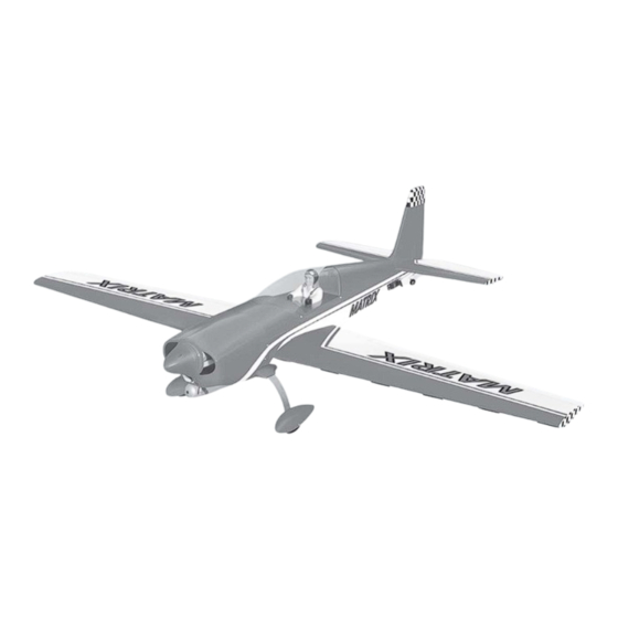
Related Manuals for Black Horse Model Matrix


Summary of Contents for Black Horse Model Matrix
- Page 1 Instruction Manual book SPECIFICATION Wingspan: 1,600 mm 63 in Wing Area: 42.08 dm 652sq.in Length 1,350 mm 53in Weight 3500gr 7.7 lbs Engine .61 cu.in 2 stroke .91 cu.in 4 stroke Radio 4 channels Servo 6 servos Made in Vietnam.
-
Page 2: Parts List
MATRIX. Instruction Manual This instruction manual is designed to help you build a great flying aeroplane. Please read this manual thoroughly before starting assembly of your MATRIX. Use the parts listing below to identify all parts. WARNING Please be aware that this aeroplane is not a toy and if assembled or used incorrectly it is capable of causing injury to people or property. -
Page 3: Safety Precaution
MATRIX. INSTRUCTION MANUAL 3. Using a modeling knife, remove the SAFETY PRECAUTION covering at possition show below. + This is not a toy + Be sure that no other flyers are using your radio frequency. Remove the covering. + Do not smoke near fuel + Store fuel in a cool, dry place, away from children and pets. -
Page 4: Instruction Manual
MATRIX. Instruction Manual 5) Instal servo tray with aileron servo into M3 lock nut. the wing as same as picture below. Wing. Aileron control horn. Servo tray. 2) Locate nylon control horns, nylon con- trol horn backplates and 3 machine screws. -
Page 5: Installing The Aileron Linkages
MATRIX. INSTRUCTION MANUAL INSTALLING THE AILERON LINKAGES 1. Working with the aileron linkage for now, thread one clevis onto one of the threaded wires. 2. Attach the clevis to the outer hole in the control horn. Install a silicone tube on the clevis. -
Page 6: Installing The Stopper Assembly
MATRIX. Instruction Manual Alumium brace. Dowel brace. INTALLING THE ENGINE MOUTH FUEL TANK INSTALLING THE STOPPER ASSEMBLY 1. The stopper has been pre-assembled at the factory. 2. Using a modeling knife, cut one length of silicon fuel line (the length of silicon fuel line is... - Page 7 MATRIX. INSTRUCTION MANUAL Blow through one of the lines to ensure the fuel lines have not become kinked inside the fuel tank compartment. Air should flow through easily. 9. To secure the fuel tank in place, apply a bead of silicon sealer to the forward area of...
- Page 8 MATRIX. Instruction Manual Locate the long piece of wire used for the Trim and cut. throttle pushrod. One end of the wire has been pre-bend in to a “Z” bend at the factory. This “Z” bend should be inserted into the throttle arm of the engine when the engine is fitted onto the engine mount.
-
Page 9: Servo Installation
MATRIX. INSTRUCTION MANUAL 4) Install the muffler and muffler extension SERVO INSTALLATION onto the engine and make the cutout in the cowl for muffler clearance. Connect the fuel 1) Install the rubber grommets and brass and pressure lines to the carburetor, muffler collets into the elevator, rudder, and throttle and fuel filler valve. -
Page 10: Horizontal Stabilizer Installation
MATRIX. Instruction Manual HORIZONTAL STABILIZER INSTALLATION Remove covering. 1) Using a modeling knife, cut away the covering from the fuselage for the stabilizer and remove it. 2) Draw a center line onto the horizontal stabilizer. Then slide the horizontal into the fuselage. - Page 11 MATRIX. INSTRUCTION MANUAL 6) When you are sure that everything is a aligned correctly, mix up a generous amount of 30 minute epoxy. Apply a thin layer to the slot in the mounting platform and to the vertical stabilizer mounting area. Apply epoxy to the lower rudder hinge.
-
Page 12: Pushrod Installation
MATRIX. Instruction Manual Rudder cable. Rudder cable. Elevator Elevator pushrod. pushrod. Control clasp. Rudder control horn.(2 sides). Elevator control horn.(2 sides). PUSHROD INSTALLATION 1) Ilevator pushrod install as same as the way of aileron control horn. 2) Rudder push - pull system install as same as picture below. -
Page 13: Mounting The Tail Wheel Bracket
MATRIX. INSTRUCTION MANUAL 1) Assemble and mounting the wheel pants MOUNTING THE TAIL WHEEL BRACKET as shown in the following pictures. 1) Set the tail wheel assembly in place on the plywood plate. The pivot point of the tail wheel wire should be even with the rudder hinge line and the tail wheel bracket should be centered on the plywood plate. -
Page 14: Installing The Receiver And Battery
MATRIX. Instruction Manual Landing gear. 3) Using the hardware provided, mount the main landing gear to the fuselage. INSTALLING THE RECEIVER AND BATTERY 1) Plug the servo leads and the switch lead into the receiver. You may want to plug... -
Page 15: Installing The Switch
MATRIX. INSTRUCTION MANUAL INSTALLING THE SWITCH 3) Turn the airplane upside down. Place 1) Cut out the switch hole using a modeling your fingers on the masking tape and carefully knife. Use a 2mm drill bit and drill out the two lift the plane . -
Page 16: Pre-Flight Check
MATRIX. Instruction Manual PRE-FLIGHT CHECK 1) Completely charge your transmitter and receiver batteries before your first day of flying. 2) Check every bolt and every glue joint in your plane to ensure that everything is tight and well bonded. 3) Double check the balance of the airplane. - Page 17 MATRIX. INSTRUCTION MANUAL 1) Remove this page from this instruction manual.
Need help?
Do you have a question about the Matrix and is the answer not in the manual?
Questions and answers