Table of Contents
Advertisement
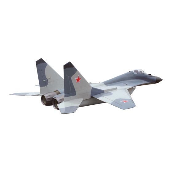
MIG-29
SCALE 1:8 ARF EDF 90MM
95% ALMOST READY TO FLY
SPECIFICATION
Wingspan: 1,420 mm (55.91 in).
Length: 2,030 mm(79.92 in).
Weight: 7.8 kg (17.16 lbs).
Wing area: 60 dm
Wing loading: 129 g/dm
Wing type: Semi-symmertrical airfoils.
Gear type: Electric retract gear
Size(LxWxH): (92.2 x 51 x 30.6) mm
(not included).
CNC Suspension Metal Struts (included).
Parts listing required (not included):
Radio: 9 channels.
Instruction Manual Book
ALL BALSA - PLY WOOD CONSTRUCTION.
COVERED WITH PVC PRINTING.
.
2
2
Item code: BH153.
Servo: 9 standard high torque servos,
size: (29.5 x 13 x 31) mm.
2 Futaba BLS 352
size: (39.9 x 20.1 x 37.1) mm elevator.
Engine: EDF 90mm (2pcs).
Battery: 2 Packs * 4S LIPO 29.6V.
ESC: 90-100A (2pcs).
Recommended EDF
and Battery set up (not included):
EDF: 90mm, Minimum thrust 3.7 kg.
Midi-fan evo/ HET 650-68-1500 WeMoTec.
Lipo cell: 8 cells/5000mAh 55C.
ESC: 100A Phoenix Castle.
Made in Vietnam.
Advertisement
Table of Contents

Subscribe to Our Youtube Channel
Related Manuals for Black Horse Model MIG-29


Summary of Contents for Black Horse Model MIG-29
- Page 1 Instruction Manual Book Item code: BH153. MIG-29 SCALE 1:8 ARF EDF 90MM ALL BALSA - PLY WOOD CONSTRUCTION. COVERED WITH PVC PRINTING. 95% ALMOST READY TO FLY SPECIFICATION Servo: 9 standard high torque servos, Wingspan: 1,420 mm (55.91 in).
-
Page 2: Tools And Supplies Needed
Instruction Manual This instruction manual is designed to help you build a great flying aeroplane. Please read this manual thoroughly before starting assembly of your MIG-29. Use the parts listing below to identify all parts. WARNING Please be aware that this aeroplane is not a toy and if assembled or used incorrectly it is capable of causing injury to people or property. -
Page 3: Safety Precaution
MIG-29 Item code: BH153. Instruction Manual Caution: Wing warp: Hold the panel twisted gently in This model is not a toy! the opposite direction to the warp, If you are a beginner to this type of powered model, and apply warm air to remove the please ask an experienced model flyer for help and creases from the covering. -
Page 4: Installing The Aileron Servos
MIG-29 Item code: BH153. Instruction Manual I. AILERON Remove the covering See picture below: Bottom side. Slats Flap Aileron Thread. 1. INSTALLING THE AILERONS Test fit the ailerons to the wing with the hing- es. If the hinges don’t remain centered, stick a pin through the middle of the hinge to hold it in position. - Page 5 MIG-29 Item code: BH153. Instruction Manual Place the servo into the servo tray. Center the servo within the tray and drill 1.5mm pilot holes through the block of wood for each of the four mounting screws provided with the servo.
-
Page 6: Elevator Servo Installation
MIG-29 Item code: BH153. Instruction Manual 2. INSTALLING THE SLATS LINKAGES Bottom Repeat step # 4 from installing aileron linkage to install the slats linkage. (page 5) Slats linkages tube Wing panel. Aluminium 12mm. 287 mm Servo tray 1. A+B Epoxy glue 2. - Page 7 MIG-29 Item code: BH153. Instruction Manual Secure the EDF. 3 x 12mm Drill a hole 2.5mm secure V. INSTALLING THE EDF (ELECTRIC DUCTED FAN SYSTEM) Trim 1 hole from the air outlet for the wires of EDF. 1. A+B Epoxy glue Hole 2.Push in...
-
Page 8: Installing Horizontal Stabilizer
MIG-29 Item code: BH153. Instruction Manual 3x10mm. 40mm Push in elevator servo 1. Push in C/A glue 2. Push in VII. INSTALLING HORIZONTAL Secure STABILIZER Cacbon tube Horizontal stabilizer. 8mm. 109mm Secure Horizontal stabilizer. 2. Push in 1. A+B Epoxy glue... - Page 9 MIG-29 Item code: BH153. Instruction Manual Repeat the procedure for the opposite Horizontal stabilizer half. C/A glue. Repeat the procedure for the opposite plastic parts elevator. VIII. INSTALLING PLASTIC PARTS ELEVATOR IX. INSTALLING ELECTRIC GEAR See pictures below: RETRACTS 92.20 24.10...
- Page 10 MIG-29 Item code: BH153. Instruction Manual (Electric Not Included.) Secure Only including oleo struts. 3 x 15mm Push in Repeat the procedure for the other Gear. Pilot drill the mounting holes. Drill a hole 2.5mm Screw the gear in position.
-
Page 11: Vertical Installation
MIG-29 Item code: BH153. Instruction Manual 2. Secure 3 x 6 mm 1. Push in XI. VERTICAL INSTALLATION Rudder servo and control horn install as same as method of the aileron (page 4 - 5). Cacbon tube vertical stabilizer. 8mm. -
Page 12: Installing The Receiver
MIG-29 Item code: BH153. Instruction Manual 2) Wrap the receiver and battery pack in the protective foam to protect them from vibration. Use a rubber band or masking tape to hold the foam in place. 3) Position the battery pack and receiver is as picture below. -
Page 13: Wing Attachment
MIG-29 Item code: BH153. Instruction Manual Open Secure XIII. WING ATTACHMENT Bottom Fuselage 1) Attach the tube into the fuselage. aluminium INSTALLING THE FUSELAGE Top side. See pictures below: 2.Secure Aluminium tube Fuselage. 12mm. 276 mm 1. Push in 332 mm ... -
Page 14: Installing Cockpit Fuselage
MIG-29 Item code: BH153. Instruction Manual Fuselage Push in Wing panel Repeat the procedure for the other wing half. Use glue to secure the canopy to the fuselage. The shape of the canopy, so make sure to install it in the correct direction. -
Page 15: Control Throws
MIG-29 Item code: BH153. Instruction Manual model is “tail heavy” and you must add weigh* to XV. PLASTIC PARTS FUSELAGE the nose. If the nose drops, it is “nose heavy” and you must add weight* to the tail to balance. -
Page 16: Pre-Flight Check
MIG-29 Item code: BH153. Instruction Manual PRE-FLIGHT CHECK 12mm 12mm 1) Completely charge your transmitter and Aileron control receiver batteries before your first day of flying. 2) Check every bolt and every glue joint in 20mm your plane to ensure that everything is tight and Flap control well bonded.
Need help?
Do you have a question about the MIG-29 and is the answer not in the manual?
Questions and answers