
Related Manuals for Advantech B+B SmartWorx Vlinx MESR901


Summary of Contents for Advantech B+B SmartWorx Vlinx MESR901
- Page 1 Manual Documentation Number MESR9xx-1016m www.advantech-bb.com...
- Page 2 B+B SmartWorx Inc. 707 Dayton Road Ottawa, IL 61350 USA Phone (815) 433-5100 -- General Fax (815) 433-5105 Website: www.advantech-bb.com European Headquarters B+B SmartWorx Inc. Westlink Commercial Park Oranmore, Co. Galway, Ireland Phone +353 91-792444 -- Fax +353 91-792445 March 2016 2016 B+B SmartWorx Inc.
-
Page 3: Table Of Contents
Ethernet Master and Serial Slaves ............................46 Serial & Ethernet Masters, Serial & Ethernet Slaves......................52 Serial Masters, IP Slaves ..............................54 Identical Hard Coded Slaves ............................... 60 Identical Production Lines ..............................61 Modbus Help ..............................62 Page i Manual Documentation Number MESR9xx-1016m www.advantech-bb.com... - Page 4 Appendix C: Dimensional Diagrams ............................ 71 Appendix D: Connector Pinouts ............................75 MESR901-x Serial Port Pinouts ................75 MESR902T-x Serial Port Pinouts................77 Standard Ethernet Cable RJ-45 Pin-out ..............78 Glossary ................................79 Page ii Manual Documentation Number MESR9xx-1016m www.advantech-bb.com...
-
Page 5: Introduction
An external power supply, sold separately, is required. The photograph above is an MESR921 gateway. The MESR92x units have an additional Ethernet port which functions much like an Ethernet Switch. MESR90x units have one Ethernet port. Page 1 Manual Documentation Number MESR9xx-1016m www.advantech-bb.com... -
Page 6: Mesr9Xx Modbus Gateway Model Numbering
Models are available with one or two serial connections. Network connection options include 10BaseT/100BaseTX copper or several different fiber optic options. The following diagram shows the model numbering scheme: Page 2 Manual Documentation Number MESR9xx-1016m www.advantech-bb.com... -
Page 7: List Of Mesr9Xx Modbus Gateway Models
SM Fiber (40 km) & Copper (1) RJ-45 & (1) SC MESR922T-SC80 SM Fiber (80 km) & Copper (1) RJ-45 & (1) SC MESR922T-ST SM Fiber (15 km) & Copper (1) RJ-45 & 1 ST Page 3 Manual Documentation Number MESR9xx-1016m www.advantech-bb.com... -
Page 8: Mesr9Xx Modbus Gateway Features
Software Support - Windows 2000, XP (32/64 bit), 2003 Server (32/64 bit), Vista (32/64 bit), 2008 Server (32/64 bit), Windows 7 (32/64 bit) Configuration of Ethernet and serial port settings using Vlinx Manager software Page 4 Manual Documentation Number MESR9xx-1016m www.advantech-bb.com... -
Page 9: Vlinx Manager Configuration Software
Vlinx Manager configuration software enables you to find connected Modbus gateways, configure them, upgrade Modbus gateway firmware, and save/load configuration files. It features a graphical user interface (GUI) that is convenient and easy to use. Page 5 Manual Documentation Number MESR9xx-1016m www.advantech-bb.com... -
Page 10: Mesr9Xx Modbus Gateway Hardware
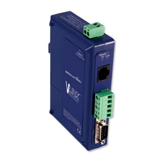
All MESR9xx Modbus Gateway models are built into similar enclosures. Modules are DIN rail mountable. The MESR92x (shown below) enclosure is larger than the MESR90x.See the specification table for dimensions. Figure 2. Front View of an MESR921 Modbus Gateway Page 6 Manual Documentation Number MESR9xx-1016m www.advantech-bb.com... -
Page 11: Led Indicators
Port LEDs blink (green) when data is being transmitted or received on the serial port. When the LED is On it indicates the serial port is open. Figure 4. Serial Port LEDs on 1 and 2 Serial Port Modbus Gateways Page 7 Manual Documentation Number MESR9xx-1016m www.advantech-bb.com... -
Page 12: Mode Switch
The Modbus gateway is connected to a standard Ethernet network drop using a straight-through RJ45 (male) Ethernet cable. Ethernet Connectors. E2 is pass-through connection on model shown Figure 6. Note: Refer to Appendix D for connection pin-outs. Page 8 Manual Documentation Number MESR9xx-1016m www.advantech-bb.com... -
Page 13: Fiber Optic Connectors
MESR922T-x Modbus Gateways feature two serial ports, both using five-position removable terminal blocks for RS-232, RS-422 and RS-485 connections. Figure 8. DB-9 Female Serial Port Connector Figure 9. Five-Position Pluggable Terminal Block Note: Refer to Appendix D for connection pin-outs. Page 9 Manual Documentation Number MESR9xx-1016m www.advantech-bb.com... -
Page 14: Power Connector
MESR9xx Modbus Gateway modules can be DIN rail mounted. The DIN mounting clip and spring is included on each module. Figure 11. DIN Clips on Modbus Gateway Modules. Large DIN clips are used on MESR92x, small DIN clips on MESR90x. Page 10 Manual Documentation Number MESR9xx-1016m www.advantech-bb.com... -
Page 15: Modbus Gateway Setup And Connections
RXB(+) and TXA(-), TXB(+), plus GND. This makes full-duplex operation possible. The data lines are differential pairs (A & B) in which the B line is positive relative to the A line in the idle (mark) state. Ground provides a common mode reference. Page 11 Manual Documentation Number MESR9xx-1016m www.advantech-bb.com... -
Page 16: Connecting The Mesr9X1-X
If you select RS-422 mode, RS-485 2-wire mode, or RS-485 4-wire mode when you configure the Modbus gateway, you must connect the Modbus network appropriately, via the 5-position terminal block. Note: Refer to Appendix D for connector pin out information. Figure 13. MESR901 Connections Page 12 Manual Documentation Number MESR9xx-1016m www.advantech-bb.com... -
Page 17: Connecting The Mesr9X2T-X
MESR902D is a DTE. If the Modbus network is a DTE, use a null modem (cross-over) cable. If the Modbus network is a DCE, use a straight-through cable. Note: Refer to Appendix D for connector pin-out information. Figure 15. MESR902D-x Connections Page 13 Manual Documentation Number MESR9xx-1016m www.advantech-bb.com... -
Page 18: Connecting Mesr9Xx Modbus Gateways To A Network
If AUTO RUN is disabled on your computer, open the CD drive and double click on the executable file. The file name is Modbus Gateway Manager Vx.x.x. a. The following screen will be displayed on your computer. Page 14 Manual Documentation Number MESR9xx-1016m www.advantech-bb.com... - Page 19 3. Setup and Connections VlinxMESR9xx Modbus Gateway Figure 16. Modbus Gateway Manager Installation Welcome Screen b. Click “Next.” The License Agreement Screen will be displayed on your computer. Figure 17. Modbus License Acceptance Screen Page 15 Manual Documentation Number MESR9xx-1016m www.advantech-bb.com...
- Page 20 Click “Next.” The Destination Folder Screen will be displayed on your computer. The default directory is: C:\Program Files\BB Electronics\Vlinx\Modbus Gateway Manager\ If desired, you can select another location by pressing the “Browse” button. Figure 19. Destination Folder Screen Page 16 Manual Documentation Number MESR9xx-1016m www.advantech-bb.com...
- Page 21 Click “Next.” The Ready to Install Application Screen will be displayed on your computer. You can select the “Back” button to change destination folder. Figure 20. Ready to Install Application Screen f. Click “Next.” The software will begin installing. Figure 21. Software Installing Screen Page 17 Manual Documentation Number MESR9xx-1016m www.advantech-bb.com...
- Page 22 Click “Next.” Figure 22. Information Screen h. Click “Next.” The Installation Complete screen will be displayed on your computer. Click “Finish” to finish the installation. Figure 23. Installation Complete Screen Page 18 Manual Documentation Number MESR9xx-1016m www.advantech-bb.com...
-
Page 23: Configuring The Mesr9Xx Modbus Gateway Via The Network Connection
1. From the Desktop, click Start Programs B+B SmartWorx Vlinx Modbus Gateway Manager. An alternate method is to double click the shortcut installed on the desktop. Figure 24. Opening Vlinx Modbus Gateway Manager Figure 25. Vlinx Modbus Gateway Manager Shortcut Icon Page 19 Manual Documentation Number MESR9xx-1016m www.advantech-bb.com... - Page 24 If you know the IP address, you may select “The Device is located at this IP address” and input the address in the box provided. Figure 27. Configuration Manager Screen Page 20 Manual Documentation Number MESR9xx-1016m www.advantech-bb.com...
- Page 25 An alternate method of accessing the configuration screens is to use the “Next” button in area C. c. This area contains dialog boxes specific the configuration screen. 1. Note: Any configuration changes you make need to be saved using the “Save” button. Page 21 Manual Documentation Number MESR9xx-1016m www.advantech-bb.com...
- Page 26 5. Diagnostic allows you to test a configured Modbus Gateway. See Section 5. 6. Monitor allows you to monitor a Modbus Gateway. See Section 5. 7. About contains information about your Modbus Gateway. 7. General Settings Figure 29. General Settings Screen Page 22 Manual Documentation Number MESR9xx-1016m www.advantech-bb.com...
- Page 27 Figure 30. Changing The Password c. Type your new password in the “Type the new password box.” Verify the password by typing it again in the box provided. To save the new password click the “Save” button. Page 23 Manual Documentation Number MESR9xx-1016m www.advantech-bb.com...
- Page 28 IP Address field contains static internet protocol address of the Modbus Gateway. Subnet Mask field contains mask that is used to define sub network. For Class A network (IP addresses 0.0.0.0 through 127.255.255.255), the default subnet mask is 255.0.0.0. Page 24 Manual Documentation Number MESR9xx-1016m www.advantech-bb.com...
- Page 29 To access this screen, click the “Next Button” or click on the Modbus TCP link on the left side of the screen. b. This screen allows you Modbus TCP client and server settings. Page 25 Manual Documentation Number MESR9xx-1016m www.advantech-bb.com...
- Page 30 TCP clients that can be connected. Choices are 1 through 16. 3. Connection Filter Mode controls which TCP clients are able to connect. The default is: “and allow everyone to connect.” Page 26 Manual Documentation Number MESR9xx-1016m www.advantech-bb.com...
- Page 31 Figure 34. TCP Connection Filter “Allow Specific IP addresses to Connect b. You can select “a specific range of IP addresses to connect.” This filter is limited to 4 IP address ranges. c. Save settings by clicking the “Save” button. Page 27 Manual Documentation Number MESR9xx-1016m www.advantech-bb.com...
- Page 32 Stop Bits – Controls the number of bits to end a character. Choices are 1 or 2. g. Parity – Controls the error checking mode. Choices are Odd, Even, Mark, or Space. h. Save settings by clicking the “Save” button. 11. Port X Modbus Page 28 Manual Documentation Number MESR9xx-1016m www.advantech-bb.com...
- Page 33 32 messages request per port. If this option is unselected, the gateway will respond with a 06h if it has a message out on the port with no response yet. Page 29 Manual Documentation Number MESR9xx-1016m www.advantech-bb.com...
- Page 34 The first box in line is the start of the remap range on the serial port you want to remap. Valid value range is from 1 to 255. d. The second box in line is the last serial port of that range. Valid value range is from 1 to 255. Page 30 Manual Documentation Number MESR9xx-1016m www.advantech-bb.com...
- Page 35 The fourth box in line is an IP address of the slave device if IP address is chosen in the third box. g. Save settings by clicking the “Save” button. 14. Modbus Priority Page 31 Manual Documentation Number MESR9xx-1016m www.advantech-bb.com...
- Page 36 IP Address – Used to set a static Internet protocol address for the Modbus Gateway. e. Modbus ID – Valid range is from 1 to 255. f. Function Code – Valid range is from 1 to 99. g. Save settings by clicking the “Save” button. Page 32 Manual Documentation Number MESR9xx-1016m www.advantech-bb.com...
- Page 37 1. On a PC connected to the network, open a web browser. Figure 41. Open Web Browser 2. In the browser’s address bar, type the IP address of the Modbus gateway. Figure 42. Type IP Address Page 33 Manual Documentation Number MESR9xx-1016m www.advantech-bb.com...
- Page 38 IP address 169.254.102.39. If this address does not work with your PC, there are two methods to manually configure the network information. 1. Method 1: Change your PC Network to Match the Modbus Gateway a. Open your network connection Page 34 Manual Documentation Number MESR9xx-1016m www.advantech-bb.com...
- Page 39 Click on Internet Protocol (TCP/IP) and click <properties>. Change the parameters to the following: IP Address = 169.254.102.1 Subnet Mask = 255.255.0.0 Default Gateway = 169.254.102.100 c. Use the Vlinx™ Modbus Manager Software to search for, discover, and configure the Modbus Gateway. Page 35 Manual Documentation Number MESR9xx-1016m www.advantech-bb.com...
- Page 40 PC Network Settings IP Address = 192.168.0.1 Subnet Mask = 255.255.0.0 Default Gateway = 192.168.0.100 Change the Modbus Gateway’s network settings to: IP Address = 192.168.0.50 Subnet Mask = 255.255.0.0 Default Gateway = 192.168.0.100 Page 36 Manual Documentation Number MESR9xx-1016m www.advantech-bb.com...
-
Page 41: Configuring The Mesr9Xx Modbus Gateway Via The Serial Port (Console Mode)
On MESR902x models: Port 1 LED is On and the Port 2 LED is Off. To configure the Modbus gateway, open the Vlinx Modbus Manager software and set up the Modbus gateway's parameters as required. 1. Under Connection, select “Serial Port.” Page 37 Manual Documentation Number MESR9xx-1016m www.advantech-bb.com... - Page 42 Serial Port Options and using the pull down menu to choose the COM port. Figure 46. Serial Port Selection 3. The remaining screens are identical to those shown in configuring your gateway using network connection. Page 38 Manual Documentation Number MESR9xx-1016m www.advantech-bb.com...
-
Page 43: Mesr9Xx Modbus Gateway Operational Connections
2. Configure the Modbus gateway with the appropriate network settings (using Vlinx Modbus Manager or the web interface). 3. Configure your software application with the appropriate IP address and port number to communicate with the Modbus network(s). Figure 47. Direct IP Connection Page 39 Manual Documentation Number MESR9xx-1016m www.advantech-bb.com... -
Page 44: Initiating A Hardware Reset On The Modbus Gateway
The Modbus gateway reloads all factory default configuration parameters. 3. The LEDs go back to their normal states when the device resumes normal operation. Note: Factor default parameters are listed in Appendix A Page 40 Manual Documentation Number MESR9xx-1016m www.advantech-bb.com... -
Page 45: Upgrading The Modbus Gateway Firmware
Other Modbus gateways (that have already been discovered) can be selected from the drop down list, if desired. The current firmware version of the selected Modbus gateway is shown in the text below the Modbus gateway name. Page 41 Manual Documentation Number MESR9xx-1016m www.advantech-bb.com... -
Page 46: Downloading Firmware Files
4. In the Firmware File drop down list, select the firmware file to upload to the Modbus gateway. 5. Click Upgrade. The Progress box and Progress bar display information on the upgrading process. 6. When the upgrade process is complete, click Close. Page 42 Manual Documentation Number MESR9xx-1016m www.advantech-bb.com... -
Page 47: Diagnostics
IP addresses, Subnet Masks and Default Gateways in use. Figure 49. Diagnostics Dialog Box Testing a Modbus Gateway Connection To run diagnostics on a Modbus gateway: 1. Click the Diagnostics icon. Diagnostics dialog box appears. Page 43 Manual Documentation Number MESR9xx-1016m www.advantech-bb.com... - Page 48 2. In the drop down box select the specific Modbus gateway you want to check. 3. Click the Start button Test Information about the progress of the pinging process is displayed in the Progress box. Figure 50. Testing a Modbus Gateway Connection Page 44 Manual Documentation Number MESR9xx-1016m www.advantech-bb.com...
-
Page 49: Monitor Function
“Clear” button clears the displayed text. “Stop” Press the button to stop monitoring. “Save” Press the button to save the information to a file. Page 45 Manual Documentation Number MESR9xx-1016m www.advantech-bb.com... -
Page 50: Application Examples
Your Modbus gateway can be used to integrate serial slave devices on a Modbus TCP network. This allows TCP Masters to control serial slave devices. The example below is using a gateway with two serial ports. Figure 51. Ethernet Master With Serial Slaves Page 46 Manual Documentation Number MESR9xx-1016m www.advantech-bb.com... - Page 51 3. Configure Serial Port 1. In this case it is RS-232, 19.2 kbps, 8 data bits, 1 stop bit, and even parity. Save the settings 4. Access Port 1 Modbus by clicking the link on the left side of the screen. Page 47 Manual Documentation Number MESR9xx-1016m www.advantech-bb.com...
- Page 52 Modbus should be RTU. The other settings depend on your application. 6. Configure Port 2 Serial and Modbus is the same fashion. 7. Access Modbus ID Remapping for each port and configure as necessary. Page 48 Manual Documentation Number MESR9xx-1016m www.advantech-bb.com...
- Page 53 8. Access Modbus ID Routing. Configure as necessary. In this example, Slave ID 200 is mapped to serial port 1, Slave ID 1 through 5 and 205 are mapped to serial port 2. Page 49 Manual Documentation Number MESR9xx-1016m www.advantech-bb.com...
- Page 54 8. Modbus Help VlinxMESR9xx Modbus Gateway Figure 55. Modbus ID Routing 9. Access Modbus Priority and configure as necessary. Page 50 Manual Documentation Number MESR9xx-1016m www.advantech-bb.com...
- Page 55 8. Modbus Help VlinxMESR9xx Modbus Gateway Figure 56. Modbus Priority Page 51 Manual Documentation Number MESR9xx-1016m www.advantech-bb.com...
-
Page 56: Serial & Ethernet Masters, Serial & Ethernet Slaves
1. In this example, Serial Port 1 has an RTU Master attached. Configure the serial port settings as appropriate for the device. Access the Port 1 Modbus screen and configure it the port for Modbus Master and RTU. Page 52 Manual Documentation Number MESR9xx-1016m www.advantech-bb.com... - Page 57 Figure 58. Port 1 Modbus 2. Configure the Modbus Slave ID routing. In this case Modbus Slaves 1 through 5 and 205 are on Serial Port 2. Modbus Slaves 150 and 151 through 160 have IP assignments. Page 53 Manual Documentation Number MESR9xx-1016m www.advantech-bb.com...
-
Page 58: Serial Masters, Ip Slaves
8. Modbus Help VlinxMESR9xx Modbus Gateway Figure 59. Modbus Slave ID Routing Serial Masters, IP Slaves Serial Masters can be used to control IP Slaves. Figure 60. Serial Masters, IP Slaves Page 54 Manual Documentation Number MESR9xx-1016m www.advantech-bb.com... - Page 59 1. In this example, and ASCII Master is connected to Serial Port 1 and an RTU Master is connected to Serial Port 2. Configure the serial ports as appropriate for these devices. Figure 61. Port 1 Serial Page 55 Manual Documentation Number MESR9xx-1016m www.advantech-bb.com...
- Page 60 Figure 62. Port 2 Serial 2. Access the Modbus screen for each port and configure as appropriate. In this case, Port 1 has an ASCII Master and Port 2 has an RTU Master attached. Page 56 Manual Documentation Number MESR9xx-1016m www.advantech-bb.com...
- Page 61 8. Modbus Help VlinxMESR9xx Modbus Gateway Figure 63. Port 1 Modbus Page 57 Manual Documentation Number MESR9xx-1016m www.advantech-bb.com...
- Page 62 8. Modbus Help VlinxMESR9xx Modbus Gateway Figure 64. Port 2 Modbus 3. Setup the Slave ID Routing to associate IP addresses with the appropriate Slave ID. Page 58 Manual Documentation Number MESR9xx-1016m www.advantech-bb.com...
- Page 63 8. Modbus Help VlinxMESR9xx Modbus Gateway Figure 65. Modbus Slave ID Routing Page 59 Manual Documentation Number MESR9xx-1016m www.advantech-bb.com...
-
Page 64: Identical Hard Coded Slaves
Identical Hard Coded Slaves In this example, two slave devices that are hard coded with the same ID are required. This is accomplished by putting them on different serial ports. Figure 66. Identical Hard Coded Slaves Page 60 Manual Documentation Number MESR9xx-1016m www.advantech-bb.com... -
Page 65: Identical Production Lines
In this example, identical or backup production lines can be controlled by the same IP Master. This allows the duplicate networks to be configured identically, saving documentation and maintenance time. Figure 67. Identical Production Lines Page 61 Manual Documentation Number MESR9xx-1016m www.advantech-bb.com... -
Page 66: Modbus Help
(e.g. it does not recognize the function code), it will return a message containing an exception response. Hints and Tips A few simple suggestions that may assist you if your system is experiencing problems include: Page 62 Manual Documentation Number MESR9xx-1016m www.advantech-bb.com... - Page 67 A sometimes difficult problem is difference in grounding voltage between various network locations. Stray voltage from lightning or other sources may also find its way onto the network. These conditions make isolation necessary in many settings. Page 63 Manual Documentation Number MESR9xx-1016m www.advantech-bb.com...
-
Page 68: Appendices
9. Appendices VlinxMESR9xx Modbus Gateway This section includes the following Appendices: Appendix A: Default Gateway Settings Appendix B: Product Specifications Appendix C: Dimensional Diagrams Appendix D: Connector Pinouts Page 64 Manual Documentation Number MESR9xx-1016m www.advantech-bb.com... -
Page 69: Appendix A: Default Gateway Settings
Baud Rate 9600 Data bits Parity None Stop bits Flow Control None Protocol Serial timeout 0 seconds Inter-character timer 0 ms TCP port Port 1 = 4000 Port 2 = 4001 Max connection Page 65 Manual Documentation Number MESR9xx-1016m www.advantech-bb.com... -
Page 70: Appendix B: Product Specifications
9. Appendices VlinxMESR9xx Modbus Gateway Appendix B: Product Specifications This section includes the following specifications: General Specifications Controls, Indicators and Connector Specifications Serial Interface Specifications Network Specifications Page 66 Manual Documentation Number MESR9xx-1016m www.advantech-bb.com... -
Page 71: General Specifications
1.2 in x 3.3 x 4.7 in (3.1 x 8.4 x 11.9 cm) Case (MESR90x) Power Supply Voltage Requirements 10 to 48 VDC (58 VDC Max) (External Supply Required) MESR90x – 4.0W (Max) Power Consumption MESR92x – 6.0W (Max) Page 67 Manual Documentation Number MESR9xx-1016m www.advantech-bb.com... -
Page 72: Controls, Indicators And Connector Specifications
SC fiber SC connector ST fiber ST connector MESR901-x: one DB-9M connector Connectors MESR902D-x: Two DB-9M connectors Serial MESR902T-x: Two pluggable lockable 5.08 mm terminal blocks 5.08mm 2-position pluggable, lockable DC Power terminal block Page 68 Manual Documentation Number MESR9xx-1016m www.advantech-bb.com... -
Page 73: Serial Interface Specifications
1, 1.5, 2 Flow control None, RTS/CTS, XON/XOFF RS-422/485 biasing Auto 4.7K ohm pullups and pulldowns Auto termination with thru hole resistor (user RS-422/485 termination supplied) RS-485 data control Auto control via MCU Page 69 Manual Documentation Number MESR9xx-1016m www.advantech-bb.com... -
Page 74: Network Specifications
Via serial, Ethernet or auto web search Character count 0 to 65535 Timeouts Character 0 to 65535 ms, default set at 10 ms Modbus Message 0 to 65535 ms, default set at 1,000 ms Serial 0 to 65535 sec Page 70 Manual Documentation Number MESR9xx-1016m www.advantech-bb.com... -
Page 75: Appendix C: Dimensional Diagrams
9. Appendices VlinxMESR9xx Modbus Gateway Appendix C: Dimensional Diagrams Figure 68. Dimensional Diagram of an MESR901 Modbus Gateway (Note: Small Case Used for MESR901 Series Units) Page 71 Manual Documentation Number MESR9xx-1016m www.advantech-bb.com... - Page 76 9. Appendices VlinxMESR9xx Modbus Gateway Figure 69. Dimensional Diagram of an MESR902T Modbus Gateway (Note: Small Case Used for MESR902 Series Units) Page 72 Manual Documentation Number MESR9xx-1016m www.advantech-bb.com...
- Page 77 9. Appendices VlinxMESR9xx Modbus Gateway Figure 70. Dimensional Diagram of an MESR921 Modbus Gateway, Left and Right Side Views (Note: Medium Case Used for MESR921 and MESR922 Series Units) Page 73 Manual Documentation Number MESR9xx-1016m www.advantech-bb.com...
- Page 78 9. Appendices VlinxMESR9xx Modbus Gateway Figure 71. Dimensional Diagram of an MESR921 Modbus Gateway, Bottom, Top, Back and Front Views (Note: Medium Case Used for MESR921 and MESR922 Series Units) Page 74 Manual Documentation Number MESR9xx-1016m www.advantech-bb.com...
-
Page 79: Appendix D: Connector Pinouts
9. Appendices VlinxMESR9xx Modbus Gateway Appendix D: Connector Pinouts MESR901-x Serial Port Pinouts DB9 M Pin Direction RS-232 Input Input Output Output Input Output Input Input Page 75 Manual Documentation Number MESR9xx-1016m www.advantech-bb.com... - Page 80 9. Appendices VlinxMESR9xx Modbus Gateway Terminal RS-422/485 4-Wire RS-485 2-Wire TDA (-) Data A (-) TDB (+) Data B (+) RDA (-) RDB (+) Page 76 Manual Documentation Number MESR9xx-1016m www.advantech-bb.com...
-
Page 81: Mesr902T-X Serial Port Pinouts
TXB(+) line to the RXB(+) line of the Modbus network, and the Modbus gateway TXA(-) to the RXA(-) of the Modbus network. Ground is signal ground and provides a common mode reference for the RS-422 Receiver and Transmitters. Page 77 Manual Documentation Number MESR9xx-1016m www.advantech-bb.com... -
Page 82: Standard Ethernet Cable Rj-45 Pin-Out
9. Appendices VlinxMESR9xx Modbus Gateway Standard Ethernet Cable RJ-45 Pin-out RJ-45 Pin Signal Wire Color White-Green Green White-Orange Not used Blue Not used White-Blue Orange Not used White-Brown Not used Brown Page 78 Manual Documentation Number MESR9xx-1016m www.advantech-bb.com... -
Page 83: Glossary
A binary digit that is added to ensure that the number of bits with value of Parity Bit one in a given set of bits is always even or odd. It may also be a Mark (1), or a Space (0). PDU Protocol Data Unit Page 79 Manual Documentation Number MESR9xx-1016m www.advantech-bb.com... - Page 84 TCP Transmission Control Protocol Unit ID Unit Identifier. This is the same as the slaves address. MESR B+B’s Modbus Ethernet Gateway Series Vlinx B+B’s family name for the Gateway line Page 80 Manual Documentation Number MESR9xx-1016m www.advantech-bb.com...
Need help?
Do you have a question about the B+B SmartWorx Vlinx MESR901 and is the answer not in the manual?
Questions and answers