Table of Contents
Advertisement
Advertisement
Table of Contents

Related Manuals for Interroll ZoneControl


Summary of Contents for Interroll ZoneControl
- Page 1 INSPIRED BY EFFICIENCY Operating Manual Interroll ZoneControl...
- Page 2 All the marks contained in this document (protected trademarks, such as logos and commercial designations) are the property of Interroll Engineering GmbH or third parties and may not be used, copied or distributed without prior written consent.
-
Page 3: Table Of Contents
Applicable documentation Product information Product description Functions Speed settings Feedback of energy / Overvoltage protection Temperature protection Lock period for signal modifications / Debouncing After-run time Setup Scope of delivery Label Technical data ZoneControl Version 2.0 (04/2019) Online Translation of the original operating manual 3 von 54... - Page 4 Downstream peer-to-peer connector: RJ45 socket, 8-pin Molex 43860 Wiring diagrams ZoneControl within the conveyor section ZoneControl at the start of the conveyor section ZoneControl at the end of the conveyor section Connection of the external speed control Connection of a second RollerDrive Initial startup and operation Version 2.0 (04/2019) Online...
- Page 5 Inhalt Commissioning Pre-commissioning checks Inspection before each commissioning Operation Speed setting Internal speed setting on the ZoneControl Speed setting via external analog signal 6.4 External influence on zero pressure accumulation conveying ZONE_STOPP ZONE_START Complete clearing of a conveyor Maintenance and cleaning Maintenance Checking the ZoneControl Replacing the ZoneControl...
-
Page 7: About This Document
The manufacturer assumes no liability for damage and malfunctions that occur as a result of non- compliance with this operating manual. Should you still have any unanswered questions after reading this operating manual, please contact Interroll customer service. Contact details for your region can be found online at www.interroll.com/contact/ Please direct any comments and suggestions regarding our operating manuals to manuals@interroll.com... -
Page 8: Warning Notices In This Document
About this document Warning notices in this document Warning notices are provided in the context in which danger can occur and describe the nature of the danger in question. They are structured according to the following examples: SIGNAL WORD Type and source of hazard Consequence(s) in the event of non-compliance Measure(s) for avoiding hazard ¾... -
Page 9: Symbols
About this document NOTE Denotes a situation that can lead to material damage. Preventive measures ¾ Symbols This symbol indicates useful and important information. ü This symbol indicates a requirement that must be fulfilled before carrying out assembly or repair work. This symbol indicates general information relating to safety. ¾ This symbol indicates an action that needs to be performed. •... -
Page 10: Safety-Related Information
The ZoneControl is not intended for use by private end users. The equipment must not be used in a residential environment without further examination and without the use of EMC protective measures that have been adapted accordingly. -
Page 11: Qualification Of Personnel
This operating manual is intended for the following target audiences: Operators Operators are trained in how to operate and clean the Interroll ZoneControl unit and follow the safety regulations. Service engineers The service engineers have a specialist technical education or have successfully completed a training course from the manufacturer. -
Page 12: Dangers
¾ Maintenance and repair work on the unit must only be carried out by authorised technical personnel in compliance with the applicable provisions. ¾ Before switching on the ZoneControl, ensure that no unauthorised personnel are situated in the vicinity of the conveyor/conveying system. -
Page 13: Interface To Other Devices
Safety-related information Interface to other devices The integration of the ZoneControl into a conveyor system can create additional potential hazards. Such potential hazards are not covered by this operating manual and must be analysed during the development, installation and commissioning of the conveyor system as a whole. Following the integration of the ZoneControl into a conveyor system, the entire system must be checked for any ¾ new potential hazards that may be present before the conveyor is switched on. Operating modes/operating phases Standard operation Operation in the installed condition at the end customer as a component in a conveyor in an overall system. -
Page 14: Applicable Documentation
Safety-related information Applicable documentation In order to ensure proper use of the RollerDrive, additional operating manuals/documentation relating to the following must be consulted: • Power supply unit • RollerDrive • Description of the conveyor system/unit Also ensure that you adhere to the information given in the operating manuals of the connected devices. Version 2.0 (04/2019) Online 14 von 54 Translation of the original operating manual... -
Page 15: Product Information
Product information Product description The ZoneControl is used to facilitate zero pressure accumulation conveying, meaning that goods are transported without coming into contact with each other. To achieve this, the conveyor is sub-divided into zones. One zone consists of a RollerDrive, several idler rollers, a ZoneControl and corresponding sensors. Zero pressure accumulation conveying is achieved by there being only one product in every zone and by the zones retaining the package until the downstream zone is detected as being „free” by the corresponding sensor. When accumulation occurs, a signal is transmitted upstream to retain the next package. A gap is always left between the goods being transported so that no accumulation pressure occurs. -
Page 16: Functions
Feedback of energy / Overvoltage protection If the RollerDrive is stopped by the ZoneControl or if the speed is reduced abruptly, the kinetic energy of the package is regeneratively converted into electrical energy in the motor. This energy is then fed back into the ZoneControl, resulting in increased voltage in the DC-net. -
Page 17: Temperature Protection
If operational conditions mean that the brake chopper is switched on so often that the upper temperature limit of approx. 90 °C (measured internally) is reached, then the ZoneControl switches off. If temperature protection is active, this is shown on the LED display. When the ZoneControl has cooled down, the RollerDrive restarts automatically when a signal is pending. -
Page 18: Setup
11 Red and green LED 6 Power supply connector PTP = Peer-to-peer connection Scope of delivery The ZoneControl contains the following components: • ZoneControl • Mating plug for power supply (WAGO 734-102/xxx-xxx) • Mating plug for power supply (WAGO 734-102/xxx-xxx) •... -
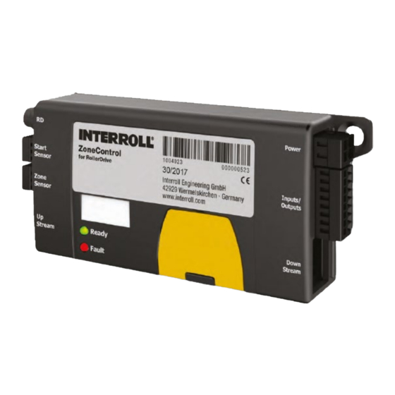
Page 19: Label
5 to 95 %, condensation not permissible condensation not permissible Max. 1000 m A single ZoneControl is protected against reverse polarity connection of the operation voltage. Polarity protection is gone as soon as assemblies are connected via PTP . Version 2.0 (04/2019) Online... -
Page 20: Meaning Of The Leds
Product information Meaning of the LEDs The LEDs indicate the operating condition of the ZoneControl and the RollerDrive and provide information about the operating voltage. LED green LED red Meaning Behaviour of RollerDrive Flashing Flashing Initialisation of ZoneControl Depending on sensor assignment... -
Page 21: Dip Switches
Product information DIP switches The DIP switches can be used to select the speed, direction of transportation, operating mode and logic conversion (PNP/NPN). Factory default of the DIP switches 1 to 3 is ON and that of DIP switches 4 to 8 is OFF. DIP switches SPEED A, B, C Speed setting (see „Speed setting”, page 40) -
Page 22: Meaning Of Signals Zone_Status
Product information Meaning of signals ZONE_STATUS The ZONE_STATUS signal is the output signal of the handshake function of the ZoneControl. The assigned signal input is ZONE_START. The ZONE_STATUS signal is active when: • The ZONE_START signal is active. • The start or zone sensor is occupied (by regular in-feed of a package or by placing a package on a previously empty zone). -
Page 23: Transport And Storage
Check each ZoneControl after transport for any visible damage. ¾ If any damage has been identified, photograph the damaged parts. ¾ In the event that damage has been incurred during transport, inform the shipping agent or Interroll ¾ immediately to ensure that you do not lose any potential damage claims. Do not expose the ZoneControl to any strong fluctuations in temperature, since this can lead to condensation ¾... -
Page 24: Assembly And Installation
An improper approach to installing the ZoneControl can lead to material damage or reduce the service life of the ZoneControl. To preserve the interior of the ZoneControl, do not allow the ZoneControl to fall or for it to be used in an ¾... -
Page 25: Warning Notices For Electrical Installation
Improper electrical installation can result in damage to the ZoneControl. Observe national regulations for electrical installation. ¾ Only operate the ZoneControl with a protective extra-low voltage (PELV) of 24 V or 48 V. ¾ Never operate the ZoneControl with an alternating voltage. -
Page 26: Electrical Installation
The cabling of the PTP connection must always following the direction of the conveyor, that is to say that the PTP downstream connection of the upstream zone must be connected to the PTP upstream connection of the downstream zone etc. This also applies if one/several ZoneControl(s) have to be fitted on the other side of the conveyor. 1 Direction of travel 4 Power supply 2 ZoneControl 5 Peer-to-peer connection 3 RollerDrive 6 Package Required cables: Version 2.0 (04/2019) Online... - Page 27 Adjust the PNP/NPN DIP switch according to the signal level being used (applies to sensors and inputs and ¾ outputs). Insert the RollerDrive connector so that the “RD” label on the ZoneControl is visible and the label on the ¾ connector faces the rear (and is therefore not visible).
-
Page 28: Signal Status Of Inputs
Assembly and installation Signal status of inputs PNP / Status ZONE_STOP ZONE_START CLEAR DIR_RET START / ZONE_SENS_ active + 24 V + 24 V + 24 V + 24 V + 24 V DIP = OFF in-active active DIP = ON in-active Signal status of outputs PNP /... -
Page 29: Sensors
Assembly and installation Sensors The following types of sensors can be connected (the sensor must be active if the package is in the detection area): • Light scanner light-switching • Light barrier dark-switching Type of Light- or Opener / Logical Light beam Switch Elektrical Output... -
Page 30: Inputs And Outputs
Assembly and installation Inputs and outputs RollerDrive connection: 8 mm snap-in, 5-pin, pin location in accordance with DIN EN 61076-2 1 +24 V DC 4 Fault input 2 Output for direction of rotation 5 Speed output 3 Ground Start sensor connector: WAGO 733-103 mating plug 1 +24 V DC 3 Ground 2 START_SENS_IN (input for start sensor signal) -
Page 31: Zone Sensor Connector: Wago 733-103 Mating Plug
Assembly and installation Zone sensor connector: WAGO 733-103 mating plug 1 +24 V DC 3 Ground 2 ZONE_SENS_IN (input for zone sensor signal) Upstream peer-to-peer connection: RJ45 socket, 8-pin Molex 43860 Mating plug: pre-manufactured patch cable Version 2.0 (04/2019) Online Translation of the original operating manual 31 von 54... -
Page 32: Power Supply Connector: Wago 734-102 Mating Plug
Assembly and installation Power supply connector: WAGO 734-102 mating plug 1 GND (Ground) 2 +24 V DC Inputs/outputs connector: WAGO 733-108 mating plug 1 EXT_ON (Output for additional start signal) 5 ERROR (Output for error signal) 2 CLEAR (Input for clear signal) 6 ZONE_STATUS (Output for zone status signal) 3 SPEED (Input for speed setting) 7 ZONE_START (Input for start signal) -
Page 33: Downstream Peer-To-Peer Connector: Rj45 Socket, 8-Pin Molex 43860
Assembly and installation Downstream peer-to-peer connector: RJ45 socket, 8-pin Molex 43860 Mating plug: pre-manufactured patch cable The electrical data for each connection is specified in the appendix (see „Electrical data of connectors”, page 50). Version 2.0 (04/2019) Online Translation of the original operating manual 33 von 54... -
Page 34: Wiring Diagrams
Assembly and installation Wiring diagrams Abbreviations used: +24 V Operating voltage Ground (Earth) Peer-to-peer Connection ZoneControl within the conveyor section 1 Zone sensor This ZoneControl can be located at any position between the start and end zone. This switch enables zero pressure accumulation conveying without additional functions. The ZoneControl is connected to the adjacent ZoneControls via the Peer-to-Peer cable. The zone sensor is fed with operating voltage via the sensor connector. Version 2.0 (04/2019) Online... -
Page 35: Zonecontrol At The Start Of The Conveyor Section
Assembly and installation ZoneControl at the start of the conveyor section 1 Start sensor 2 Zone sensor 3 Switch A: External signal at the ZONE_START input Handshake to the upstream conveyor section: The zone status (occupied or free) can be queried via the signal ZONE_ STATUS. (see „ZONE_STATUS”, page 22). The first zone of the ZoneControl conveyor can be started in the following ways: • Start sensor (button A is not needed) • External signal at the ZONE_START input (symbolised by switch A; start sensor not needed) The function of the switch can be provided using any switching element (e. -
Page 36: Zonecontrol At The End Of The Conveyor Section
Assembly and installation ZoneControl at the end of the conveyor section 1 Zone sensor 2 Button: External signal at the ZONE_START input When the package has reached the sensor in the last zone it is stopped by default. An external signal must be given at the ZONE_START input of the last zone to discharge. This can be a switch (refer to the example in the diagram above) or an external control (PLC). The signal can be switched in NPN or PNP mode. The status of the last zone is given by the ZONE_STATUS output. If there is no package in the relevant zone sensor’s detection range and the ZONE_START signal is active, the RollerDrive does not rotate. Depending on signal length and discharge mode (single or train release) either one or more packages will be released. -
Page 37: Connection Of The External Speed Control
An external SPEED signal can be connected to control the speed of the whole conveyor externally. The signal should only be connected to one ZoneControl, as it is transmitted via the PTP connection to all other ZoneControl. The position of the ZoneControl within the conveyor and the cable length of the PTP connection is immaterial. -
Page 38: Connection Of A Second Rollerdrive
If the function DIR_RET is to be used in the application, connect the DIR input of the DriveControl 20 to the ¾ DIR_RET signal of the ZoneControl and on the DriveControl 20 set the DIP switch DIR in such a way that the RollerDrive is rotating in the correct direction. -
Page 39: Initial Startup And Operation
Danger of crushing of limbs and damage to goods! Ensure that no unauthorised persons are near the conveyor before switching on the operating voltage. ¾ The ZoneControl is initialised after the operating voltage has been applied. The ZoneControl is then brought into a defined basic state and packages that are not within the detection range of a sensor are transported onto the next zone sensor. The RollerDrives in unoccupied zones rotate and RollerDrives in occupied zones do not rotate. The start and end zones are automatically detected if they are wired correctly. Initialisation mode takes 4 seconds. During the... -
Page 40: Speed Setting
Initial startup and operation Speed setting Internal speed setting on the ZoneControl Requirement: The external SPEED input is not connected or in-active. Set the required speed using the DIP switches (see table). ¾ It is not possible to stop the RollerDrive by connecting ground to the external SPEED input. -
Page 41: Speed Setting Via External Analog Signal
Set the speed of the RollerDrives by changing the external signal within a range of 1 to 10 V. Changes to the ¾ signal will only be applied if they differ by at least 0.1 V from the previous value. Set the external signal to 0 V to enable the internal speed setting by the DIP switch. ¾ The specified analog speed applies to all zones of the ZoneControl conveyor. External influence on zero pressure accumulation conveying The ZoneControl has two control signals to specifically influence the otherwise automatic conveyor process: • ZONE_START • ZONE_STOPP These signals enable the current conveyor logic of a zone to be interfered with to the extent that locally generated START-STOP processes can be integrated easily and simply into the parallel running global ZPA conveyor process. -
Page 42: Zone_Start
Initial startup and operation ZONE_START The ZONE_START signal is the input signal of the handshake function of the ZoneControl. The associated signal output is ZONE_STATUS (siehe „ZONE_STATUS”, Seite 22). • Connected to the first zone of the conveyor: • The start signal leads to the RollerDrive in the first zone starting, providing that the zone sensor is not occupied. • If the zone sensor is occupied, the RollerDrive will not be started. • If the signal is active while a package is conveyed into the first zone, the RollerDrive will continue running until the package reaches the sensor (resulting in no Time-Out).. -
Page 43: Complete Clearing Of A Conveyor
If the DIR_RET signal is active parallel to the CLEAR signal, all of the connected RollerDrive rotate in the opposite direction than set by the DIP switch. DIR_RET and CLEAR must be connected to the same ZoneControl. The DIR_RET signal is only effective during CLEAR. -
Page 44: Maintenance And Cleaning
¾ Maintenance Checking the ZoneControl The ZoneControl itself requires no maintenance. However, in order to prevent faults from occurring, the connections and fixings must be examined on a regular basis. In the course of regular inspection and maintenance work on the conveyor, ensure that the screws of the ¾... -
Page 45: Cleaning
Never immerse the ZoneControl in fluids. ¾ If necessary, vacuum any dust or dust that is present. ¾ To clean the ZoneControl more thoroughly, disconnect it from the power supply, detach it and wipe it with a ¾ damp cloth. Version 2.0 (04/2019) Online Translation of the original operating manual... -
Page 46: Troubleshooting
Troubleshooting Troubleshooting Troubleshooting Symptom Possible Cause Help ZoneControl is not working or is No power supply Check whether the output ¾ working incorrectly voltage of the power supply is within the specified voltage range. Check the connections and ¾ correct if necessary. Wrong position of the DIP switches Check and if necessary ¾... - Page 47 Overheating of chopper resistor to Allow to cool down. ¾ > 90 °C The ERROR signal is automatically reset after elimination of the fault and the ZoneControl immediately performs a local reinitialisation of the affected zone. PTP cable disconnection Check all of the PTP cable ¾...
-
Page 48: Deviations In The Conveying Process
RollerDrive stops. The ERROR output becomes active and the next ZoneControl displays an error by means of the error LED. An assumption is made that the package is blocking the conveyor. -
Page 49: Decommissioning And Disposal
Switch off the power to the ZoneControl and ensure that it cannot be unintentionally switched on again. ¾ Decommissioning Remove all cables from the ZoneControl. ¾ Loosen the screws that have been used to attach the ZoneControl to the conveyor frame. ¾ Remove the ZoneControl from the conveyor frame. ¾ Disposal The operating company is responsible for disposing of the ZoneControl according to correct procedure. In doing so, the industry-specific and local provisions for disposing of the ZoneControl and its packaging must be observed. -
Page 50: Appendix
Appendix Appendix 10.1 Electrical data of connectors Inputs/outputs connectors Inputs ZONE_START, ZONE_STOP , DIR_RET, CLEAR, START_SENS_IN and ZONE_SENS_IN Properties 24 V logic, debounced, GND reference potential Reverse polarity protection max. 30 V DC Overvoltage protection max. 30 V DC Permanent, free of harmonic waves Logic level low 0 to 5 V DC npn = active... -
Page 51: Rollerdrive Connector
Appendix RollerDrive connector Power supply (Pin 1, 3) Nominal value 24 V DC Voltage range 18 to 26 V DC Residual ripple max. 600 mV Rated current 0 to 2,3 A Peak current max. 5 A max. 250 ms > 2.3 A, time-dependent current flow triangular, duty factor ≤ 19 % Return electric strength... - Page 52 Appendix Input error (Pin 4) Properties Not galvanically separated Reverse polarity protection Max. 30 V DC Max. voltage 30 V DC Logic level, low Max. 8.5 V DC at 1.5 mA Logic level 0 = L = no error Residual current, low 1.5 mA Max.
-
Page 53: Translation Of The Original Declaration Of Conformity
List of the coordinated standards that have been applied: EN 60947-5-3:1999/A1:2005 EN 61000-6-2:2005/AC:2005 EN 61000-6-3:2007/A1:2011/AC:2012 EN 60204-1:2006/AC:2010 Authorised for compiling technical documentation: Interroll Engineering GmbH, Höferhof 16, 42929 Wermelskirchen, Germany Jörg Schiffler Product Compliance Officer, Interroll Engineering GmbH Wermelskirchen 01.02.2019 Version 2.0 (04/2019) Online Translation of the original operating manual... - Page 54 INSPIRED BY EFFICIENCY © 2019 INTERROLL...
Need help?
Do you have a question about the ZoneControl and is the answer not in the manual?
Questions and answers