
Related Manuals for Falcon Dominator Plus G3800


Summary of Contents for Falcon Dominator Plus G3800
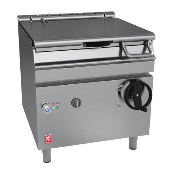
- Page 1 USERS, INSTALLATION AND SERVICING INSTRUCTIONS GAS BRATT PAN G3800 and G3800DX DATE PURCHASED: MODEL NUMBER: SERIAL NUMBER: DEALER: T100753 Rev. 3 SERVICE PROVIDER: Published: 04 /10/2012...
- Page 2 Dear Customer, Thank you for choosing Falcon Foodservice Equipment. This manual can be downloaded from www.falconfoodservice.com where you also can see the full range of our products and latest news. Alternatively, scan the code below using a mobile device IMPORTANT: Please keep this manual for future reference.
-
Page 3: Table Of Contents
CONTENTS 1.0 INTRODUCTION ........................... 4 2.0 OPERATION .......................... 6 2.1 Controls ............................ 6 2.2 Using the Bratt Pan ........................ 7 3.0 GETTING THE MOST OUT OF THE APPLIANCE .............. 8 4.0 CLEANING AND MAINTENANCE .................... 8 5.0 SPECIFICATION ........................... ... -
Page 4: Introduction
1.0 INTRODUCTION This appliance has been CE-marked on the basis of compliance with the Gas Appliance, Low Voltage and EMC Directives for the heat inputs, gas pressures and voltages stated on the data plate. 4 ... -
Page 5: Servicing 1
IMPORTANT! It is most important that these instructions be consulted before operating, installing and commissioning this appliance. Failure to comply with the specified procedures may result in damage or the need for a service call. The installer must ensure that the installation of the appliance is in conformity with these instructions and National Regulations in force at the time of installation. -
Page 6: Operation
2.0 OPERATION 2.1 Controls 6 ... -
Page 7: Using The Bratt Pan
2.2 Using the Bratt Pan 1. Ensure pan is fully lowered using the pan tilting handle. 2. Ensure mains gas is turned on. 3. Plug in the appliance and turn the mains electricity ON. The red neon will illuminate. 4. Turn thermostat control knob to desired temperature. The flame will auto ignite and the green neon will illuminate. -
Page 8: Getting The Most Out Of The Appliance
3.0 GETTING THE MOST OUT OF THE APPLIANCE SAVE ENERGY AND RUNNING COST BY TURNING OFF THE APPLIANCE WHEN NOT IN USE. Griddling Note that the centre of the pan is hotter than the edges when griddling. Simmering and Stewing Lid can be left slightly ajar if a gentle simmer is desired. -
Page 9: Specification
5.0 SPECIFICATION 5.1 Model Number covered in this group of products G3800 800mm wide manual lift gas Bratt Pan G3800 DX 800mm wide manual lift gas Duplex Bratt Pan 5.2 Technical Data TECHNICAL DATA – TABLE A Gas Type Natural Propane Injector diameters... -
Page 10: Dimensions / Connection Locations
6.0 DIMENSIONS / CONNECTION LOCATIONS 10 ... -
Page 11: Installation
7.0 INSTALLATION 7.1 Unpacking 1. Remove all packaging from the appliance. 2. Remove all plastic coatings. 3. Ensure there are no missing parts. 4. Ensure that no damage is evident. 7.2 Siting / Clearances Well lit draught free area. 150mm 150mm from any combustible wall. -
Page 12: Ventilation
7.3 Ventilation Adequate ventilation must be provided to supply sufficient fresh air* for combustion and allow easy removal of combustion products which may be harmful to health. Recommendations for Ventilation of Catering Appliances are given in BS5440:2. For multiple installations the requirements for individual appliances should be added together. -
Page 13: Water Supply
7.6 Water Supply Connection to the water supply is via a 15mm compression fitting at rear. Water supply pressure should not exceed 500kPa (5 bar). 7.7 Assembly 1. Position appliance and carefully level using feet adjusters as shown below. 2. -
Page 14: Conversion
8.0 CONVERSION 8.1 GAS CONVERSION CHECK LIST Change burner pressure at valve in accordance with section 5.2. CHANGE INJECTORS CHANGE DATA PLATE Ensure gas supply is disconnected before commencing. Only reconnect gas supply after all conversion work has been completed. Burner and pilot Injectors a) Remove front panel. -
Page 15: Servicing
9.0 SERVICING BEFORE ATTEMPTING ANY SERVICING, ENSURE THE APPLIANCE IS UNPLUGGED FROM MAINS SUPPLY CANNOT INADVERTENTLY TURNED ON. AFTER ANY MAINTENANCE TASK, CHECK APPLIANCE TO ENSURE THAT IT PERFORMS CORRECTLY AND CARRY OUT ANY NECESSARY ADJUSTMENTS AS DETAILED IN ‘COMMISSIONING’. Symbols on drawings: denotes a pozi-head screw requires removal. - Page 16 When removing the front fascia, care should be taken not to damage the neon cables. 16 ...
- Page 17 NEONS Neons are attached to the front fascia. To replace them, remove the connections and the nut. OPERATING THERMOSTAT The operating thermostat is located on the pan underside. To replace, remove the phial clamp from the underside of the pan by removing the two nuts. Pull out thermostat phial and feed it down into the electrics box.
- Page 18 When replacing the thermostat phial back into the clamp, ensure that the phial is pushed right back into the clamp and re-attach the vidaflex. SAFETY THERMOSTAT Safety thermostat is located on the underside of the pan. Push the button protruding out from the bottom of the box to reset.
- Page 19 TILT SWITCH Tilt switch is located beside the electrics box. INJECTORS The injectors for the burner and pilot can be accessed from the front of the appliance while the front panel is removed. BURNERS Lift pan fully up to get access to the burner. Access to the burner pipe is from the front of the appliance while the front panel is removed.
-
Page 20: Wiring Diagram
9.1 Wiring Diagram 20 ... -
Page 21: Circuit Diagram
9.2 Circuit Diagram 21 ... -
Page 22: Fault Finding
10.0 FAULT FINDING FAULT POSSIBLE CAUSES REMEDY Red neon not lighting. No power from the supply. Restore supply. Faulty mains supply cord. Replace supply cord. Faulty neon Replace neon Green neon not lighting but Tilt Switch not activated or Ensure pan is lowered in the Red neon is on. -
Page 23: Service Information
12.0 SERVICE INFORMATION In order to obtain maximum performance from this appliance we would recommend that a maintenance contract be arranged with SERVICELINE. Visits may then be made at agreed intervals to carry out adjustments and repairs. A quotation will be given upon request to the contact number below: SERVICELINE CONTACT: Phone: 01438 363 000... - Page 24 Warranty Policy Shortlist Warranty does not cover the following:- • Correcting faults caused by incorrect installation of a product. • Where an engineer cannot gain access to a site or a product. • Repeat commission visits. • Replacement of any parts where damage has been caused by misuse. •...
Need help?
Do you have a question about the Dominator Plus G3800 and is the answer not in the manual?
Questions and answers