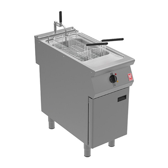
Falcon F900 Series User, Installation And Servicing Instructions
Neutral unit
Hide thumbs
Also See for F900 Series:
- User, installation and servicing instructions (58 pages) ,
- User, installation and servicing instructions (37 pages) ,
- User, installation and servicing instructions (12 pages)
Table of Contents
Advertisement
Quick Links
Advertisement
Table of Contents

Summary of Contents for Falcon F900 Series
- Page 1 F900 SERIES User, installation and servicing instructions NEUTRAL UNIT N940, N940D, N940DR, N940T, N941, N960, N960D, N960DR, N961, N910, N920 Read these instructions before use DATE PURCHASED: MODEL NUMBER: SERIAL NUMBER: DEALER: SERVICE PROVIDER: REV. 6 T100893 Published: 12/10/2016...
- Page 2 Dear Customer, Thank you for choosing Falcon Foodservice Equipment. This manual can be downloaded from www.falconfoodservice.com or scan here. IMPORTANT: Please keep this manual for future reference. Falcon Foodservice Equipment HEAD OFFICE Wallace View, Hillfoots Road, Stirling. FK9 5PY. Scotland.
- Page 3 SYMBOLS • • SCREWDRIVER • COOKING OIL • GREASE SPANNER • • FLAME • WARNING • VIEWPORT SPARK IGNITION • •IGNITER ALLEN KEY...
- Page 4 We recommend supplementary electrical protection with the use of a residual current device (RCD) The appliance has been designed and approved to use Falcon Kick plates, non Falcon kick plates could potentially adversely affect the performance of the appliance by restricting the air to the appliance.
-
Page 5: Table Of Contents
CONTENTS APPLIANCE INFORMATION ..................6 SPECIFICATION ......................7 DIMENSIONS / CONNECTION LOCATIONS ..............8 INSTALLATION ......................11 ASSEMBLY ......................11 EQUIPOTENTIAL CONNECTION ................ 11 SUITING ....................... 11 SPARE PARTS ......................14 SERVICING INFORMATION ..................14... -
Page 6: Appliance Information
1 APPLIANCE INFORMATION This appliance has been CE-marked on the basis of compliance with the relevant EU directives for the heat inputs, gas pressures and voltages stated on the data plate. A - Serial No B - Model No C - Flue Type D - Gas Category E - Gas Pressure F - Gas Type... -
Page 7: Specification
2 SPECIFICATION Model Description N940 400mm unit N940D 400mm unit with left hand door N940DR 400mm unit with right hand door N940T 400mm worktop unit N941 400mm unit with side guides N960 600mm unit N960D 600mm unit with left hand door N960DR 600mm unit with right hand door N961... -
Page 8: Dimensions / Connection Locations
3 DIMENSIONS / CONNECTION LOCATIONS... -
Page 11: Installation
4 INSTALLATION 4.1 ASSEMBLY 4.1.1 Position appliance and level using feet or castor adjusters as shown below. 4.2 EQUIPOTENTIAL CONNECTION 4.2.1 This appliance is also provided with a terminal for connection of an external equipotential conductor. This terminal is in effective electrical contact with all fixed exposed metal parts of the appliance, and shall allow the connection of conductor having a nominal cross-section area of up to 10mm². - Page 12 This can be supplied by Falcon part no – 523400021 4.3.5 Run a bead of silicon 5 mm from profile edge as highlighted below.
- Page 13 4.3.7 Right hand unit: Screw the M5 x 40 screw (supplied in the kit) into one of the suiting plates as shown and then insert through the front fixing holes of both units. 4.3.8 (B) Left hand unit: Slide the penny and lock washer on to the screw and secure using the M5 nut.
-
Page 14: Spare Parts
5 SPARE PARTS F900 SCREW CAP KIT 533550009 NEUTRAL UNIT LH HINGE KIT 533810001 400 LH DOOR ASSY 533810000 MAGNET CATCH ASSY 533810003 ADJUSTABLE LEG 150MM 535480067 SWIVEL CASTOR SET OF 2 535400222 FIXED CASTOR SET OF 2 530964340 ST/ST ADJUSTABLE FEET 535150025 NEUTRAL UNIT RH HINGE KIT 533810004...


Need help?
Do you have a question about the F900 Series and is the answer not in the manual?
Questions and answers