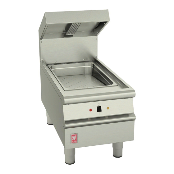
Falcon DOMINATOR PLUS E3405 Installation And Servicing Instructions
Chip scuttle
Hide thumbs
Also See for DOMINATOR PLUS E3405:
- User instructions (2 pages) ,
- User instructions (3 pages) ,
- Installation and servicing instruction (9 pages)
Table of Contents
Advertisement
Quick Links
DOMINATOR PLUS E3405 CHIP SCUTTLE
INSTALLATION and
SERVICING INSTRUCTIONS
Caution : Read the instructions before
using this appliance.
IMPORTANT
The installer must ensure that the installation of the appliance is in conformity with these instructions and National
Regulations in force at the time of installation. Particular attention MUST be paid to –
BS7671 IEE Wiring Regulations
Electricity at Work Regulations
Health And Safety At Work Act
Fire Precautions Act
This appliance has been CE-marked on the basis of compliance with the Low Voltage and EMC Directives for the
voltages stated on the Data Plate
WARNING -THIS APPLIANCE MUST BE EARTHED
On completion of the installation these instructions should be left with the Engineer-in-Charge for reference during
servicing. Further to this, The Users Instructions should be handed over to the User, having had a demonstration of
the operation and cleaning of the appliance.
IT IS MOST IMPORTANT THAT THESE INSTRUCTIONS BE CONSULTED BEFORE INSTALLING AND COMMISSIONING
THIS APPLIANCE. FAILURE TO COMPLY WITH THE SPECIFIED PROCEDURES MAY RESULT IN DAMAGE OR THE NEED
FOR A SERVICE CALL.
PREVENTATIVE MAINTENANCE CONTRACT
In order to obtain maximum performance from this unit we would recommend that a Maintenance Contract be
arranged with SERVICELINE. Visits may then be made at agreed intervals to carry out adjustments and repairs. A
quotation will be given upon request to the contact numbers below.
WEEE Directive Registration No. WEE/DC0059TT/PRO At end of unit life, dispose of appliance and
any replacement parts in a safe manner, via a licenced waste handler.
units are designed to be dismantled easily and recycling of all material is encouraged whenever
practicable.
Falcon Foodservice Equipment
HEAD OFFICE AND WORKS
Wallace View, Hillfoots Road, Stirling. FK9 5PY. Scotland.
SERVICELINE CONTACT
Phone: 01438 363 000
Fax: 01438 369 900
T100824 Ref.3
Advertisement
Table of Contents

Subscribe to Our Youtube Channel
Related Manuals for Falcon DOMINATOR PLUS E3405


Summary of Contents for Falcon DOMINATOR PLUS E3405
- Page 1 DOMINATOR PLUS E3405 CHIP SCUTTLE INSTALLATION and SERVICING INSTRUCTIONS Caution : Read the instructions before using this appliance. IMPORTANT The installer must ensure that the installation of the appliance is in conformity with these instructions and National Regulations in force at the time of installation. Particular attention MUST be paid to –...
- Page 2 IMPORTANT INFORMATION Warranty Policy Shortlist Warranty does not cover :- Correcting faults caused by incorrect installation of a product. Where an engineer cannot gain access to a site or a product. Repeat commission visits. Replacement of any parts where damage has been caused by misuse. Engineer waiting time will be chargeable.
-
Page 3: Section 1 - Installation
SECTION 1 - INSTALLATION UNLESS OTHERWISE STATED, PARTS WHICH HAVE BEEN PROTECTED BY THE MANUFACTURER ARE NOT TO BE ADJUSTED BY THE INSTALLER. MODEL NUMBERS, NETT WEIGHTS and DIMENSIONS Model Width Depth Height Weight (mm) (mm) (mm) (kg) E3405 SITING The appliance should be installed on a level, fireproof surface, in a well lit and draught free position. -
Page 4: Electrical Ratings
ELECTRICAL RATINGS Electrical loading is as stated in table below and also on appliance data plate. The location of mains isolating switch should be identified for use in any event of an emergency or during cleaning. Connection A @ 230V SECTION 2 - ASSEMBLY and COMMISSIONING Note The following information should be read as applicable to the unit being assembled. -
Page 5: Maintenance
SECTION 3 - SERVICING and MAINTENANCE BEFORE ATTEMPTING ANY MAINTENANCE, ISOLATE APPLIANCE AT MAIN SWITCH AND TAKE STEPS TO ENSURE THAT IT IS NOT INADVERTENTLY SWITCHED ON. 3.1 CONTROL PANEL REMOVAL Remove 2 panel fixings from below hob. Release 3 fixings from below control panel. Pull panel forward slightly from below and allow it to slide down until clear. -
Page 6: Section 4 - Spares And Accessories
SECTION 4 - SPARES and ACCESSORIES When ordering spare parts, please quote model number, serial number and voltage stated on data plate. Red neon Amber neon On/off switch Element ceramic Element tubular... -
Page 7: Circuit Diagram
CIRCUIT DIAGRAM ON / OFF Switch Amber Neon To Control Panel Tag... -
Page 8: Wiring Diagram
WIRING DIAGRAM R6359 MAINS CABLE R6430 TO CONTROL PANEL R7044 R5530 RV101 RV100 R5219...
Need help?
Do you have a question about the DOMINATOR PLUS E3405 and is the answer not in the manual?
Questions and answers