Table of Contents

Subscribe to Our Youtube Channel
Related Manuals for Falcon DOMINATOR Series


Summary of Contents for Falcon DOMINATOR Series
- Page 1 DOMINATOR SERIES User, installation and servicing instructions FLEXI PAN E3741 Read these instructions before use DATE PURCHASED: MODEL NUMBER: SERIAL NUMBER: DEALER: SERVICE PROVIDER: T101031 Rev No: 1 Published: 10/10/2019...
- Page 2 Dear Customer Thank you for choosing Falcon Foodservice Equipment. This manual can be downloaded from www.falconfoodservice.com or scan here: IMPORTANT: Please keep this manual for future reference. Falcon Foodservice Equipment HEAD OFFICE Wallace View, Hillfoots Road, Stirling. FK9 5PY. Scotland.
- Page 3 SYMBOLS SCREWDRIVER SPANNER COOKING OIL GREASE WARNING SPARK IGNITION FLAME VIEWPORT ALLEN KEY IGNITER C SPANNER REMOVE DEVICE PLUG REMOVER...
- Page 4 Ensure the supply cord is routed free from the appliance to avoid damage. The appliance has been designed and approved to use Falcon kick plates; non Falcon kick plates could potentially adversely affect the performance of the appliance by restricting the air to the appliance.
- Page 5 Training and competence To help ensure the safe use of this appliance there is a requirement for you to provide whatever information, instruction, training and supervision as is necessary to ensure, so far as is reasonably practicable, the health and safety of all users. For further help and information on training and competence we would refer you the Health and Safety Executive website;...
-
Page 6: Table Of Contents
CONTENTS APPLIANCE INFORMATION ..................6 OPERATION ......................7 COMPONENT PARTS ......................7 CONTROLS ..........................8 USING THE APPLIANCE – AS A GRIDDLE ................9 USING THE APPLIANCE – BOILING / BRAISING ..............9 USING THE APPLIANCE – STEAMING ................9 CLEANING AND MAINTENANCE ................ -
Page 7: Appliance Information
1.0 APPLIANCE INFORMATION This appliance has been CE-marked on the basis of compliance with the relevant EU directives for the heat inputs, gas pressures and voltages stated on the data plate. A - Serial No B - Model No C - Flue Type D - Gas Category E - Gas Pressure F - Gas Type... -
Page 8: Operation
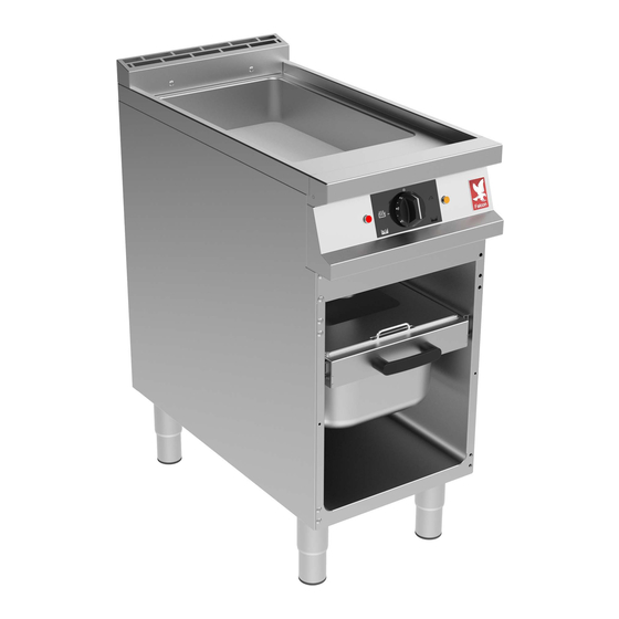
2.0 OPERATION 2.1 COMPONENT PARTS Gastronorm Slide Heat Demand Neon (Amber) Gastronorm Tray Power Neon (Red) Control Knob Level Gauge Runner Plug Removal Tool Plug... -
Page 9: Controls
2.2 CONTROLS Power Neon (Red) Simmer Position Temperature Control (Knob) Steaming Position Griddle Position Heat Demand Neon (Amber) Constant Boil Position... -
Page 10: Using The Appliance - As A Griddle
THIS APPLIANCE IS NOT DESIGNED FOR DEEP FRYING. DEEP FRYING IN THIS APPLIANCE MAY LEAD TO FIRES. 2.3 USING THE APPLIANCE – AS A GRIDDLE 2.3.1 Before use, clean the appliance inside and out. See section 3. 2.3.2 Ensure the plug is fitted. 2.3.3 Power Neon (Red) will light when there is mains power to the appliance 2.3.4 Turn Temperature Control to Griddle Position (around 280 2.3.5 Heat Demand Neon (Amber) will light as the heating elements heat the pan. -
Page 11: Cleaning And Maintenance
2.5.6 This setting is recommended for vegetables. To steam proteins a higher setting may be more suitable. E3741 12L MARK, E3781 24L MARK - NEVER FILL THE PAN ABOVE THIS MARK WITH COLD LIQUID. MIN LEVEL MARK – WHEN BOILING/BRAISING/STEAMING NEVER ALLOW THE LIQUID LEVEL TO DROP BELOW THIS MARK. -
Page 12: Cleaning And Maintenance
NOTE: All surfaces are easier to clean if spillages are removed before becoming burnt on, and the appliance is cleaned daily. It should be noted that certain scouring pads including nylon types can easily mark stainless steel. Care should be exercised during cleaning process. When rubbing stainless steel with a cloth, always rub in the direction of the grain. -
Page 13: Specification
3.1.6 Soak the Gastronorm Tray in hot soapy water. 3.1.7 Wash, rinse and dry gastronorm thoroughly. 3.1.8 Replace the Plug and fill the pan with hot soapy water to the MIN mark. 3.1.9 Clean pan with soft, clean cloth and rub away any stubborn staining with a non abrasive pad. -
Page 14: Technical Data Table
4.2 TECHNICAL DATA TABLE E3741 CURRENT POWER MIN (A) @ MAX (A) @ ACTUAL (A) @ PHASE (kW) @ 230V 230V 230V 230V 9.13 10.65 10.14 2.33 9.13 10.65 10.14 2.33 9.13 10.65 10.14 2.33 IF ANY CURRENT IS OUT WITH THESE TOLERANCES, THE CAUSE MUST BE INVESTIGATED AND RECTIFIED. -
Page 15: Installation
6.0 INSTALLATION Electrical Safety and Advice Regarding Supplementary Electrical Protection Commercial kitchens and foodservice areas are environments where electrical appliances may be located close to liquids, or operate in and around damp conditions or where restricted movement for installation and service is evident. The installation and periodic inspection of the appliance should only be undertaken by a qualified, skilled and competent electrician;... -
Page 16: Assembly
6.1 ASSEMBLY 6.1.1 Position the appliance and level using feet adjusters as shown below. TAKE CARE WHEN MOVING AN APPLIANCE FITTED WITH CASTORS. 6.1.2 Fix appliance to the floor using the anti tilt device as shown below (fit to rear of unit). -
Page 17: Electric Supply & Connection
ANTI TILT BRACKET MUST BE FITTED ON THIS UNIT 6.2 ELECTRIC SUPPLY & CONNECTION The location of the electrical inlet is as seen in section 5.0. this unit is suitable for AC supplies only. The standard terminal arrangement is Three phase (400V 3N~) for all variants. -
Page 18: Commissioning
THIS APPLIANCE MUST BE EARTHED 6.3 COMMISSIONING Refer to section 2.0 for operation. If Safety Thermostat is activated, refer to section 7.3 to reset it. Carry out the following operation:... -
Page 19: Servicing
6.3.1 Turn on mains power supply on. 6.3.2 Ensure Red Neon illuminates. 6.3.3 Turn Temperature Control Knob to 280 6.3.4 Ensure Amber Neon illuminates. 6.3.5 Let the pan heat up. When Amber Neon switches off, check the temperature in the middle of the plate. -
Page 20: Gastronorm And Slide Removal
7.1 GASTRONORM AND SLIDE REMOVAL 7.1.1 Remove gastronorm tray as section 3.1.5. 7.1.2 To remove gastronorm slide push down on left hand catch as shown and push up on right hand catch. 7.2 CONTROL AND INFILL PANEL REMOVAL 7.2.1 Remove control and infill panels as shown. 7.2.2 Fuse is located behind the control panel. -
Page 21: Safety Thermostat Reset
7.3 SAFETY THERMOSTAT RESET 7.3.1 If the appliance unexpectedly turns off, the safety thermostat might have activated. To reset follow the instructions below: 7.3.2 Turn Temperature Control to “Off Position”. 7.3.3 Allow unit to cool. 7.3.4 Isolate unit. 7.3.5 Remove Control Panel as shown in 7.2.1. 7.3.6 Depress reset switch. -
Page 22: Temperature Control And Neon Removal
7.4 TEMPERATURE CONTROL AND NEON REMOVAL 7.4.1 Remove control panel as shown in 7.2.1. 7.4.2 Remove temperature control as shown. 7.4.3 Remove neon as shown above. 7.5 CONTACTOR REMOVAL 7.5.1 Remove control panel as shown in 7.2.1 7.5.2 Remove contactor as shown above. -
Page 23: Operating Thermostat Removal
7.6 OPERATING THERMOSTAT REMOVAL 7.6.1 Remove panels as section 6.2. 7.6.2 Remove bolts from safety thermostat stop bracket. Thus enables bracket to sit loosely on the capillary and not attached to insulation tray 7.6.3 Undo four nuts with washers on inner insulation tray, remove insulation tray from unit. - Page 25 7.6.4 Undo two phial clamp fixing screws as shown above. 7.6.5 Remove the four standoffs to release the two clamping plates that hold the phial bracket in position. Ensure when re-fitting phial clamp fixing screws that these are not over tightened and stand proud of bracket as shown above.
-
Page 26: Safety Thermostat Removal
7.7 SAFETY THERMOSTAT REMOVAL 7.7.1 Follow step 7.6.2 7.7.2 Undo screws on mounting rail as shown above. Pull safety stat from sleeve as shown. Ensure when refitted the tip of the thermostat is tight up against the stop. -
Page 27: Heating Elements Removal
7.8 HEATING ELEMENTS REMOVAL 7.8.1 Follow steps 7.6.1 to 7.6.6. 7.8.2 Remove the element clamping plates as shown above. 7.8.3 Remove the elements as shown above 7.8.4 Replace in reverse order. -
Page 28: Circuit Diagrams
7.9 CIRCUIT DIAGRAMS 7.9.1 E3741Circuit diagram... -
Page 29: Wiring Diagrams
WIRING DIAGRAMS 7.9.2 E3741 Wiring diagram... -
Page 30: Accessories
8.0 ACCESSORIES 8.1 STEAMING TRAY AND LID 8.1.1 Place steaming tray and lid into pan area and follow recommended operations from section 2.5. 9.0 FAULT FINDING POSSIBLE FAULT REMEDY USER CAUSES Unit will not turn Check mains power is No power to unit connected and turned on Allow plate temperature... -
Page 31: Spare Parts
10.0 SPARE PARTS PART DESCRIPTION SPARES NUMBER Power neon red 730962010 Heat Demand Neon (Amber) 730962040 Operating Thermostat 733700000 Temperature Control Knob 733700001 Safety Thermostat 733700002 Centre Element 733700003 Side Element 733700004 Contactor 734310440 Gastronorm Tray 733700009 Gastronorm Slide 733700005 Gastronorm Slide Runners (Pair) 733700006 Drain Plug...
Need help?
Do you have a question about the DOMINATOR Series and is the answer not in the manual?
Questions and answers