Table of Contents
Advertisement
Quick Links
Advertisement
Table of Contents

Related Manuals for FAAC E850S


Summary of Contents for FAAC E850S
- Page 1 Kit E850S Translation of the original instructions...
- Page 2 Nessuna parte di questo manuale può essere riprodotta, archiviata, distribuita a terzi né altrimenti copiata, in qualsiasi formato e con qualsiasi mezzo, sia esso elettronico, meccanico o tramite fotocopia, senza il preventivo consenso scritto di FAAC S.p.A. Tutti i nomi e i marchi citati sono di proprietà dei rispettivi fabbricanti.
-
Page 3: Table Of Contents
4.4 Removing the plastic covers........10 4.5 Connections to the board E850S ....... 11 5. -
Page 4: Introduction To The Instruction Manual
Risk of tripping over due to the presence of thresholds higher than 5mm 3 Symbols: personal protective equipment Personal protective equipment must be worn to protect against hazards (e.g. crushing, cutting, shearing etc.): Obligation to wear work gloves Obligation to wear safety footwear Kit E850S 532181 - Rev.A... -
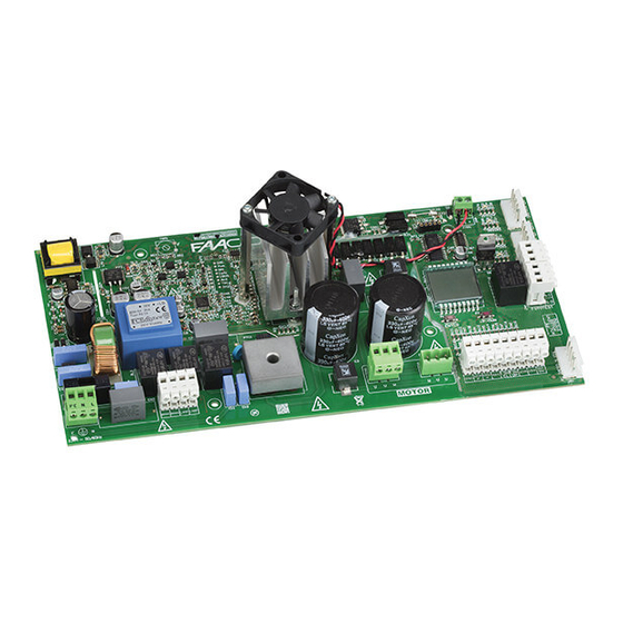
Page 5: Kit E850S
2.3 TECHNICAL CHARACTERISTICS E850S includes: - the electronic board E850S for controlling the gearmotor C850 - a new support frame for the board E850S - a new cable for connecting the integrated limit switches... - Page 6 T10A MOTOR OPEN SX OPEN DX PE N L 230V~ 2 6 Board technical data E850S E850S Power supply terminal board Power supply voltage 230 V~(+6% -10%) 50/60 Hz Electric brake and flashing light terminal board Max power...
-
Page 7: Preliminary Operations
6. U n s c r e w t h e e l e c t r i c m o t o r c a b l e g l a n d ( 7-3). Remove the electric motor cable from the cable gland 5 ( 7-4). 7. Disconnect the remaining wires from the electronic board E850. Remove the wires from the conduits. 6 3 7 Kit E850S 532181 - Rev.A... -
Page 8: Removing The Original Frame
2. Unscrew the cable gland from the limit switch unit (11 -2). 3. Disconnect the cable lugs from the micro switches and remove the limit switch cable from the cable gland (1 1 -3). 8 11 9 1 0 Kit E850S 532181 - Rev.A... -
Page 9: Installation
2. Insert the ring cable lugs into the electric motor cable gland ( 1 6 ). 3. Connect the ring cable lugs to the electric motor as follows: Grey/Black Blue 15 W1 Brown 1 2 16 1 3 17 Kit E850S 532181 - Rev.A... -
Page 10: Installing The New Frame
4.4 REMOVING THE PLASTIC COVERS 1. Place the new frame on the base in the same position as the old 1. Unscrew the 7 fixing screws from the plastic covers of the E850S frame 19). board. Remove the plastic covers (22). -
Page 11: Connections To The Board E850S
4.5 CONNECTIONS TO THE BOARD E850S ELECTRIC BRAKE 1. Fasten the electric brake cable to the cable clip on the frame (28-1). LIMIT SWITCHES 2. Make a hole in the cable gland seal. Insert the electric brake 1. Fasten the limit switch cable to the cable clips on the frame cable into the cable gland seal (2 8-2). - Page 12 3. Connect the wires of the motor to the three-pole terminal follow- If a FAAC model RP receiver is used, it is recommended to install the ing the colours indicated in 3 1 . appropriate external antenna in order to obtain a sufficient range.
- Page 13 3 9 shows the connection of one pair and two pairs of photocells (connected in series). In this configuration, if one or more of the SAFE, FSW OP inputs are not used, bridge them with NC of J6. Kit E850S 532181 - Rev.A...
-
Page 14: Start-Up
2. Install the high voltage protection cover on the board E850S and fasten it in place using the 4 screws that were put aside previously ( 4 1 ). -
Page 15: Limit Switch Adjustment
8. Using a screwdriver, turn screw number 2 clockwise until the cam engages the micro switch, as shown in 5 0. When the micro 1 -R.OP - switch is activated, the LED DL5 (OP) turns off. 49 2 -OP - 50 Kit E850S 532181 - Rev.A... - Page 16 54 Tighten the central screw of the limit switch unit by one turn (55). Replace the cover of the limit switch unit using the screws that were put aside previously ( 5 6). 55 56 Kit E850S 532181 - Rev.A...
-
Page 17: Programming
Immediate closure after transit across photocells not enabled (with automatic closing enabled, the gate always closes after the pause time) enabled (with automatic closing enabled, the gate closes immediately after transit across the closing photocells) Kit E850S 532181 - Rev.A... -
Page 18: Putting Into Service
- checked that the C850and the installed devices are working properly. DL5 OP opening limit switch not engaged engaged 1. Install the low voltage protection cover on the board E850S and DL6 OP closing limit switch not engaged engaged fasten it in place using the 3 screws that were put aside previously DL7 R.OP... - Page 20 FAAC S.p.A. Soc. Unipersonale Via Calari, 10 - 40069 Zola Predosa BOLOGNA - ITALY Tel. +39 051 61724 - Fax +39 051 758518 www.faac.it - www.faacgroup.com Kit E850S 532181 - Rev.A...
Need help?
Do you have a question about the E850S and is the answer not in the manual?
Questions and answers