FAAC E124 Rapid Manual
Hide thumbs
Also See for E124:
- Original instructions manual (44 pages) ,
- Manual (32 pages) ,
- Rapid manual (25 pages)
Advertisement
Quick Links
Pre-installation Checks
Please ensure that the correct cabling has been installed prior to commissioning of the system, as
incorrect cabling can prevent the unit from operating correctly immediately or after installation.
BUS-2EASY ENCODER and PHOTOCELLS Cable Specification: 2 core 0.5mm2 Multi-Strand Shielded Cable
with the Sheath connected to the Earth at one end. Please do not share BUS-2EASY devices with other DC
Voltage devices as it leads to electrical noise causing interference with the digital data on BUS-2EASY.
Motor Cable Specification: Minimum 2 core 2.5mm2 Multi-Strand Cable for a recommended distance of
10mtrs, further distances are possible but will require thicker cable.
Advertisement

Related Manuals for FAAC E124


Summary of Contents for FAAC E124
- Page 1 Pre-installation Checks Please ensure that the correct cabling has been installed prior to commissioning of the system, as incorrect cabling can prevent the unit from operating correctly immediately or after installation. BUS-2EASY ENCODER and PHOTOCELLS Cable Specification: 2 core 0.5mm2 Multi-Strand Shielded Cable with the Sheath connected to the Earth at one end.
-
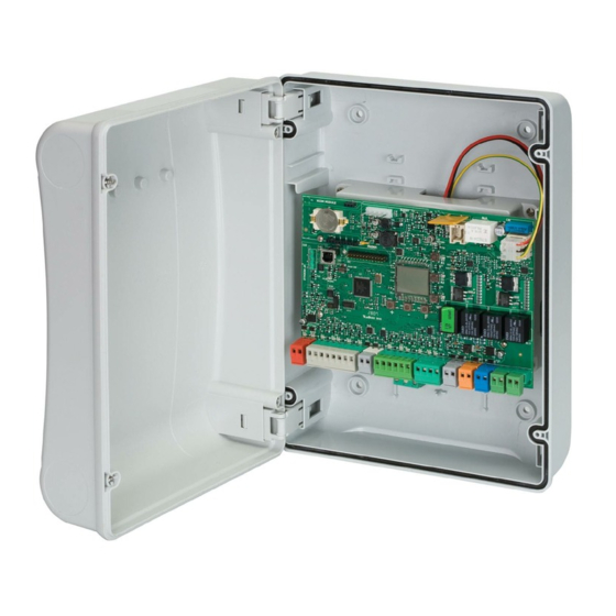
Page 2: Description Of Key Components
The installer should still familiarise themselves with the full manual and the safety information contained within. (available at https://www.faac.co.uk/accessories-and-control-boards/control- boards/for-swing-gates/e124-control-board) Key Components of E124 Board Description of Key Components SIGNALS AND PROGRAMMING DISPLAY “FCA2” STATUS LED -LIMIT SWITCH OPEN – IF GATE CLOSED ON “+”... - Page 3 The below shows a typical wiring of a set of photocells outside across the opening (closing safety) and a set of photocells inside beyond the arc of the gate (opening and closing safety) and the STOP circuit linked out and confirming the as shown below LED’s are lit.
- Page 4 Leaf 1 Leaf 2 Leaf 2 Leaf 1 Leaf 1 Leaf 2...
- Page 5 Please note that if you have a mixed system i.e. A S700H/S800H and a S800H ENC or 413 and 418, this will require the use of Easyboard software. A Windows laptop or Mac Laptop with a Type A to Type B USB lead will be required. Available to download from https://faac.biz/documents/?drawer=Software*EasyBoard...
- Page 6 Please note that for the majority of systems the default power and speed settings will be sufficient to allow the first setup. These values will generally require further adjustments if force limitation is being used as part of the safety systems and a new setup should be run after the power settings are changed.
- Page 7 The below in the figure is what should be seen as an example for a double gate that is using encoders.
- Page 8 The above is the Status references is what will be seen under normal operation, even if the alarm LED is illuminated. To identify the error the signalling Errors and Alarms procedure should be followed.
- Page 9 The following parameters from Advanced Programming may also need to be changed if the SETUP continues to fail. The following shows the typical wiring of a Maglock using either OUT 1 or OUT 2 with a relay and separate power supply, which are configurable in the Advanced Programming by holding “F”...
Need help?
Do you have a question about the E124 and is the answer not in the manual?
Questions and answers