
Related Manuals for FAAC E1SL


Summary of Contents for FAAC E1SL
- Page 1 E1SL SDK EVO LK EVO KS EVO This document contains updated instructions starting from the FW versions indicated: E1SL FW 3.4 SDK EVO FW 3.4 LK EVO FW 1.3 KS EVO FW 1.0...
- Page 2 Nessuna parte di questo manuale può essere riprodotta, archiviata, distribuita a terzi né altrimenti copiata, in qualsiasi formato e con qualsiasi mezzo, sia esso elettronico, meccanico o tramite fotocopia, senza il preventivo consenso scritto di FAAC S.p.A. Tutti i nomi e i marchi citati sono di proprietà dei rispettivi fabbricanti.
-
Page 3: Table Of Contents
1. ELECTRONIC MODULE E1SL ........ -
Page 4: Electronic Module E1Sl
1. ELECTRONIC MODULE E1SL The E1SL electronic module is designed to control FAAC automation risks that are not covered by the standard or by the manufacturers of models A1000, A1400 AIR, RKE 1400, SF1400, GBF1500. The instal- the components. FAAC S.p.A. recommends that you always comply lation instructions must be followed. -
Page 5: Status Leds On The Board
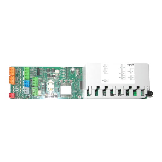
Removable terminal board configurable outputs O1, O2 Connector for main power supply 36 V, 4 A Connector for motor M1 Connectors for optional modules NOT USED Connector for motor M1 encoder Connector for motor block and monitoring 4 E1SL 532258 04 - Rev. B... -
Page 6: Dm Board
(3). 2. Unscrew the 2 screws (4) and remove the plastic cap, pulling out the 2 pins (5). 3. Install the DM board Refer to 6, install the 4 posts (6) on the E1SL DL11 RESET/SETUP board and fasten them using the screws provided (7). Insert the... - Page 7 Installing the DM board 6 2 nd MOTOR connection black 7 E1SL 532258 04 - Rev. B...
-
Page 8: Operating Mode (Modfun)
TOTAL 100% OPEN PARTIAL ( TOTAL 100% NIGHT PARTIAL ( TOTAL 100% INTERLOCK TWO-DIRECTIONAL PARTIAL ( TOTAL 100% INTERLOCK EXIT ONLY PARTIAL ( TOTAL 100% INTERLOCK ENTRY ONLY PARTIAL ( E1SL 532258 04 - Rev. B... -
Page 9: Connections
- XV1 or XDT1 detectors, single or double, exit and entry, for open- ing and safety in closing - XBFA ON detectors for safety in opening - Configurable inputs - Configurable outputs - LK EVO, KS EVO, SDK EVO function selectors E1SL 532258 04 - Rev. B... -
Page 10: Configurable Inputs
E1, E2 (TERMINAL BOARD J7) (NO) RESET (NO) E2 Configurable input E2 G GND Accessories power supply negative and Common contacts E1 Configurable input E1 DL11 BAT1 BAT2 SIC _ OP SIC _ CL EMERG OPEN E1SL 532258 04 - Rev. B... -
Page 11: Automatic Opening Inputs
- Programmed input WITH MEMORY: when the status of the input is restored, a RESET has to be carried out in order for the automation to start operating normally again. E1SL 532258 04 - Rev. B... -
Page 12: Configurable Outputs
DL11 O1 Open Collector output OUT1 Max load 100 mA GND Accessories power supply negative and Common contacts +24 V " accessories power supply BAT1 BAT2 SIC _ OP SIC _ CL EMERG OPEN E1SL 532258 04 - Rev. B... -
Page 13: Start-Up
7. START-UP RISKS Board display SDK EVO display x.x version (SDK EVO FW version) (E1SL FW version) SETUP flashing light PERSONAL PROTECTIVE EQUIPMENT (SETUP request) (SETUP request) - If there are ERRORS, see § Diagnostics Section. 2. Check the input status LEDs on the board (§ Diagnostics Section). -
Page 14: Setup
/PROGRAMMING/INSTALLATION/MOTOR ROTATION - from SDK EVO: select STANDARD NON STANDARD SETUP/RESET start SETUP close the automation open the automation 9 Restoring factory settings RESET/SETUP 5 s within 4 s of switching on 10 E1SL 532258 04 - Rev. B... -
Page 15: Programming The Board
- The SDK EVO also allows programming from the board to be disabled: /PROGRAMMING/MISCELLANEUS/BOARD'S DISPLAY BLOCKED NOT BLOCKED PROGRAMMING FROM THE BOARD The E1SL has two Programming Menus: Basic and Advanced (relative Table). Access ADVANCED programming ■ BASIC programming 1. -
Page 16: Basic Programming
Opening force level … Force time on obstacle for CF and OF … s Adjustment step = 0.1 s Deceleration ramp when OP and CL level … Acceleration ramp when OP and CL level … E1SL 532258 04 - Rev. B... - Page 17 - simultaneously to in NIGHT PAUSE Door ERROR (Press display the active ERROR) CLOSING LO-L2 SETUP in progress - phases OPEN or STOPPED or CLOSED in EMERGENCY in MANUAL operating mode in SLEEP mode (flashing dot) E1SL 532258 04 - Rev. B...
-
Page 18: Advanced Programming
DOUBLE MOTOR KIT ACTIVATION = second motor kit not enabled = second motor kit enabled - NOT displayed for SF1400 ( ) or for GBF1500 ( NIGHT-TIME MODE DELAY … s Adjustment step = 1 s E1SL 532258 04 - Rev. B... - Page 19 After exit, the display shows automation status. (See in Basic programming) INPUTS status shown on the Advanced Programming display, function segment lit = input active (OFF = segment always off) Manual Release Safeties TEST E1SL 532258 04 - Rev. B...
-
Page 20: Movement Parameters
Among the possible solutions provided, the installation of ESPE equipment compliant with EN 12978 CAT.2 (per EN 954-1 and / or PARTIAL PHARMACY EN 13849) is recommended, to monitor the full width of the door in - from Board Advanced Programming: E1SL 532258 04 - Rev. B... -
Page 21: Date And Time
(1000…1000000, modifiable in steps of 10000 cycles) …DATE (optional) 00/00/00 = disabled …CYCLES RESET (technician PSW required) Resets the RELATIVE cycles counter OK The ABSOLUTE cycles counter can only be reset using the Restore Factory Defaults procedure. E1SL 532258 04 - Rev. B... -
Page 22: Timer
Programming is carried out via the SDK EVO, it requires a clock bat- Carry out the same procedure for any other time bands. DO NOT program tery to be installed on board E1SL ( 2) and the date and time to JOLLY time bands that overlap. -
Page 23: Accessories
1. Install the motor block following the installation instructions. C Manual release microswitch 3 yellow 2. Connect the motor block to the E1SL board using the connector (A). 4 white D Motor block coil (connected at the factory) 3. If installed, connect the monitoring device (B) to the terminal 5 brown board of the motor block. -
Page 24: Xm Lock Motor Block And Monitoring
(if present) before connecting or disconnecting the motor block. 1. Install the motor block following the installation instructions. 2. Connect the motor block to the E1SL using the connector (A). 3. If installed, connect the monitoring device (B) to the terminal board of the motor block. -
Page 25: One Dual Technology Entry And Exit Detector
XDT1 exit and entry detector in compliance with EN 16005:2012 and DIN18650. The default programming of the E1SL corresponds to the typical example configuration shown in the figure. Example: configuration with dual technology entry and exit detectors. This configu-... -
Page 26: Dual Technology Entry And Exit Detectors
SERIES connection of 2 external infrared detectors and 2 internal infrared detectors. External Internal pink pink DL11 XDT1 XDT1 grey grey pink pink BAT1 XDT1 XDT1 BAT2 grey grey SIC _ OP SIC _ CL EMERG OPEN 15 E1SL 532258 04 - Rev. B... -
Page 27: Infrared Detector For Safety In Opening
The XBFA ON infrared detectors allow safety in opening in compliance with EN 16005:2012 and DIN18650. The default programming of the E1SL corresponds to the typical example configuration shown in the figure. Example: configuration with 2 infrared detectors at the exit. -
Page 28: Xfa Button Photocells
+ RX1 + TX2 + TX1 blue grey blue grey grey grey 2nd pair receiver connection GND Receiver negative 1st pair receiver connection 2nd pair transmitter connection GND Transmitter negative 1st pair transmitter connection 19 E1SL 532258 04 - Rev. B... -
Page 29: Intercom
ASSIGNING AN ID - /PROGRAMMING/INTERCOM/ID: select INTERCOM connection with boards in a cascade configuration 1 - 15 J18 E1SL, E1RD Assign a different to each board. There must be a board with ID1 (MASTER). If INTERLOCK, INTERLEAVES, or AIRSLIDE operation is J2 AIRSLIDE associations (tables in ... -
Page 30: Interlock
OPEN the access. If this condition is not met, the OPEN com- mand is not executed and an "OPEN-request” is generated. The "OPEN-request” it is carried out as soon as both accesses are E1SL closed again. Use one-direction radar detectors (see relative section). -
Page 31: Airslide
AIRSLIDE: using 3 cascade connected-wires E1SL E1AS (AIRSLIDE) DIP switch SW4 - connect the inputs of E1AS (J1) to the outputs of E1SL (J22) as in Associated 1 2 3 4 Example 1 in the figure. 1 0 0 1 2. -
Page 32: Interleaves
E.g. EMERG OPEN connected to ID2 for the emergency opening of ID2 only. With SDK EVO connected to the first E1SL: MODFUN input The MODFUN is set on the MASTER (ID1). - /PROGRAMMING/INTERCOM…... -
Page 33: Fw Updates And File Download - Usb
SDK EVO allows the firmware versions (APP) of the SDK EVO, the 1. With the board switched on, insert the USB memory device into E1SL board, the DM board, if the DM KIT is installed, and the installed connector J17, then press and release the RESET button. -
Page 34: Diagnostics
input not active (sensors not engaged) ■ EMERG (GREEN) mergency Input input active (door opened in emergency) input not active ■ OPEN (GREEN) INPUT input active input not active E1SL 532258 04 - Rev. B... -
Page 35: Automation And Configured Inputs Status
The FW version of the board appears when switched on. SDK EVO Manual Release Safeties TEST allows the FW versions of the SDK EVO, the E1SL board, the DM board, if the DM KIT is installed, and the installed devices to be displayed. /INFO - from SDK EVO: 27... -
Page 36: 1 Errors And Warnings
MANUAL MODE IN PROGRESS Manual mode operation. PARTIAL MODE IN PROGRESS Partial mode operation. OBSTACLE DETECTED WHEN CLOSING Check for and remove the obstacle. OBSTACLE DETECTED WHEN OPENING Check for and remove the obstacle. E1SL 532258 04 - Rev. B... - Page 37 Check the connections. If the error persists, the communication channel of the board, the SDK EVO, or both BOARD COMMUNICATION ERROR are damaged. Replace the board or the SDK EVO. SDK EVO CONNECTED TO A BOARD THAT IS NOT RECOG- Check the type of board. NISED E1SL 532258 04 - Rev. B...
-
Page 38: Reset
Input Terminal board Button ↑ ↑ + ( 5 s) After 5 s the corresponding LEDs ( ↑ ↑ and ) start to flash. RESET Release when the Error LEDs turn off. E1SL 532258 04 - Rev. B... -
Page 39: 2 Troubleshooting Guide
Automation in NIGHT-TIME mode. Automation in MANUAL mode. The door does not perform SETUP Active internal or external release. The emergencies are active. Motor or encoder not connected, not powered or faulty. E1SL 532258 04 - Rev. B... -
Page 40: Lk Evo
( 1 3). 3 0 Assembling the LK EVO LK EVO connection Connect to the terminals as shown. TX RX G K G V E1SL/E1RD V RX TX G V RX U/UTP CAT.5 4x2xAWG24 ... -
Page 41: Lk Evo Lock Device
FW 2.9 SETUP data missing or corrupted FW 3.0 Total deletion of board data FW 3.1 E1SL 532258 04 - Rev. B... -
Page 42: Ks Evo
( LED Error Codes). 3 1 Assembling the KS EVO KS EVO connection Connect to the terminals as shown. E1SL / E1RD V RX V RX TX G U/UTP CAT.5 4x2xAWG24 ... -
Page 43: Sdk Evo
SDK EVO connection Connect to the terminals as shown. Data reception +24 V " (accessories power supply) V RX E1SL/ E1RD - use a 4 twisted pair U/UTP AWG24 cable with a maximum length V RX TX G of 50 m 5. -
Page 44: Home Page
- select ( ↑ ↓ ) and confirm (OK) the digits of the PSW one by one, then confirm the * the TECHNICIAN PSW is required to access the programming func- complete PSW tions in the MENU 35 E1SL 532258 04 - Rev. B... -
Page 45: Modfun
- ESC button to go back to the HOMEPAGE - OK button to access the function/confirm the programming and go back to the MENU MENU - > 1 LANGUAGE - 2 PROGRAMMING - 3 ERRORS - 4 WARNINGS ↑ ↓ 3 6 E1SL 532258 04 - Rev. B... -
Page 46: Functions Menu
OK see § Diagnostics ERRORS JOLLY SLOTS TECHNICIAN PSW OK see § Diagnostics PASSWORD WARNINGS USER PSW OK OK CYCLES NUMBER SDK EVO CYCLES COUNT INFO E1SL MAINTENANCE ---- DM (*) CYCLES RESET E1SL 532258 04 - Rev. B... - Page 47 INPUTS / OUTPUTS PARTIAL PHARMACY OUTPUTS O1/O2 SDK EVO KEY INPUTS S1- S2 CONSECUTIVE OBST. INPUTS E1- E2 TEST ERROR PHOTOCELLS XFA BACKLIGHT DISPLAY OK MOTION OPENING ELASTIC KIT CLOSING MOVEMENT DAMP. STOP MOV E1SL 532258 04 - Rev. B...
-
Page 48: Menu 1 Language
This is available if the SDK EVO is connected to the board ID=1 and allows all the boards in the network to be recognised. Allows the emergency battery kit to be enabled, specifying the movements carried out in the various operating modes. NODE LIST E1SL 532258 04 - Rev. B... -
Page 49: Menu 3 Errors
SLOT. Carry out the same procedure for the other INTERVALS required. MENU 3 ERRORS The display shows current errors (§ Diagnostics Section). MENU 4 INDICATIONS The display shows current alerts (§ Diagnostics Section). E1SL 532258 04 - Rev. B... -
Page 50: Menu 8 Password
TECHNICIAN PASSWORD. MENU 9 INFO Allows the firmware versions (APP) of the SDK EVO, the E1SL board, the DM board, if the DM KIT is installed, and the installed devices to be viewed. E1SL 532258 04 - Rev. B... - Page 51 E1SL 532258 04 - Rev. B...
- Page 52 FAAC S.p.A. Soc. Unipersonale Via Calari, 10 - 40069 Zola Predosa BOLOGNA - ITALY Tel. +39 051 61724 - Fax +39 051 09 57 820 www.faac.it - www.faacgroup.com E1SL 532258 04 - Rev. B...
Need help?
Do you have a question about the E1SL and is the answer not in the manual?
Questions and answers