Table of Contents
Advertisement
1
WARNINGS ....................................................................................................................2
2
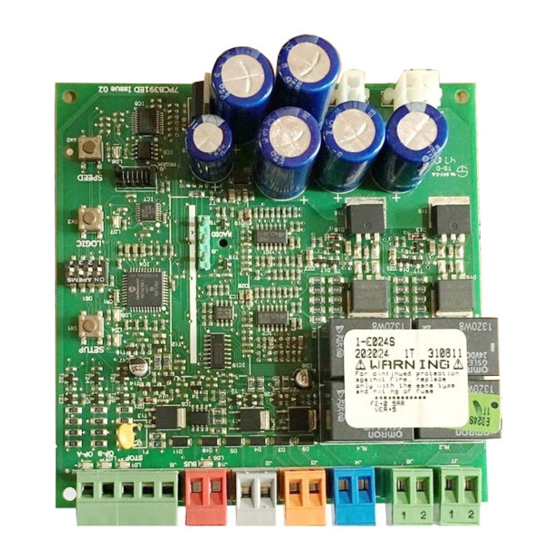
LAYOUT AND CONNECTIONS .........................................................................................2
3
TECHNICAL SPECIFICATIONS ........................................................................................3
3.1
DESCRIPTION OF COMPONENTS ........................................................................................... 3
3.2
DESCRIPTION OF TERMINAL-BOARDS .................................................................................... 3
4
PROGRAMMING THE LOGIC ..........................................................................................3
5
PROGRAMMING THE SPEED ...........................................................................................3
6.
START-UP ........................................................................................................................4
6.1
LEDS CHECK ........................................................................................................................ 4
6.2
PROGRAMMING THE DIPS-SWITCH ........................................................................................ 4
6.3
PRE-FLASHING .................................................................................................................... 4
6.4
TIME - SETUP LEARNING ....................................................................................................... 4
6.4.1 AUTOMATIC SET-UP ........................................................................................................................ 4
6.4.2 MANUAL SET-UP ............................................................................................................................. 4
7
INSTALLATION OF BUS ACCESSORIES .............................................................................5
7.1
ADDRESSING THE BUS PHOTOCELLS ..................................................................................... 5
7.2
MEMORY STORAGE OF BUS ACCESSORIES.......................................................................... 6
8
MEMORY STORING THE RADIO CODE ............................................................................6
8.1
MEMORY STORAGE OF DS RADIO CONTROLS ...................................................................... 6
8.2
MEMORY STORAGE OF SLH RADIO CONTROLS .................................................................... 6
8.3
MEMORY STORAGE OF LC RADIO CONTROLS (for some markets only) ............................. 7
8.3.1 REMOTE MEMORY STORAGE OF LC RADIO CONTROLS ................................................................. 7
8.4
RADIO CONTROLS DELETION PROCEDURE ........................................................................... 7
9
CONNECTION OF BUFFER BATTERIES (OPTIONAL) ...........................................................7
10
AUTOMATED SYSTEM TEST..............................................................................................7
11
LOGIC TABLES ...............................................................................................................8
Manufacturer: FAAC S.p.A.
Address:
Via Benini, 1 - 40069 Zola Predosa BOLOGNA - ITALY
Declares that: Control board mod. E024,
• conforms to the essential safety requirements of the following EEC directives:
73/23/EEC and subsequent amendment 93/68/EEC.
89/336/EEC and subsequent amendment 92/31/EEC and 93/68/EEC
Additional information:
This product underwent a test in a typical, uniform configuration.
(all products made by FAAC S.p.A)
Bologna 01-06-2007.
• Important! For the safety of people, it is important that all the instructions be carefully observed.
• Incorrect installation or incorrect use of the product could cause serious harm to people.
• Carefully read the instructions before beginning to install the product and keep them for future
reference.
• The symbol
indicates notes that are important for the safety of persons and for the good condition
of the automated system.
• The symbol
product.
INDEX
CE DECLARATION OF CONFORMITY
WARNINGS
draws your attention to the notes on the characteristics and operation of the
The Managing Director
A. Bassi
1
Advertisement
Table of Contents

Related Manuals for FAAC E024


Summary of Contents for FAAC E024
-
Page 1: Ce Declaration Of Conformity
Manufacturer: FAAC S.p.A. Address: Via Benini, 1 - 40069 Zola Predosa BOLOGNA - ITALY Declares that: Control board mod. E024, • conforms to the essential safety requirements of the following EEC directives: 73/23/EEC and subsequent amendment 93/68/EEC. 89/336/EEC and subsequent amendment 92/31/EEC and 93/68/EEC Additional information: This product underwent a test in a typical, uniform configuration. -
Page 2: Warnings
CONTROL UNIT E024 1 WARNINGS Before attempting any work on the control unit (connections, maintenance), always turn off power. - Install, upstream of the system, a differential thermal breaker with adequate tripping threshold, - Always separate power cables from control and safety cables (push-button, receiver, photocells, etc.). -
Page 3: Technical Specifications
3.2 DESCRIPTION OF TERMINAL-BOARDS 3 TECHNICAL SPECIFICATIONS Power supply voltage 230Vac (+6% -10%) - 50Hz Terminal and/or Description Device connected terminal-board Absorbed power 150W x 2 Motor max. load Power supply for +24V accessories Accessories max. current 100 mA (+24V) Negative BUS Accessories max.current 400 mA... -
Page 4: Start-Up
6.4 TIME - SETUP LEARNING 6 START-UP 6.1 LEDS CHECK Before any manoeuvre is executed, a SETUP cycle must first be run. The following table shows that status of the LEDs in relation to the status of the inputs (the closed at rest automated system During SETUP do not interrupt the photocells condition is shown in bold). -
Page 5: Installation Of Bus Accessories
If the A Logic was selected, the board begins to count the pause time (max 10 min) and, after the required time has elapsed, give an OPENING pulse to continue the proce- dure. Otherwise, if you have selected the EP logic, give an OPEN pulse to continue the procedure. -
Page 6: Memory Storage Of Bus Accessories
7.2 MEMORY STORAGE OF BUS ACCESSORIES You can add the BUS photocells to the system at any time, simply by memory-storing them on the board, observing the following procedure: Install and program the accessories using the required address (see paragraph 7.1) Cut power to the board. -
Page 7: Memory Storage Of Lc Radio Controls (For Some Markets Only)
Quickly press twice the memory stored radio control push- The LED on the board relating to the channel being learned button. flashes for 5 sec., within which time the code of another radio control must be transmitted. The automated system performs one opening The LED lights up on steady beam for 2 seconds, indicating operation. -
Page 8: Logic Tables
11 LOGIC TABLES...
Need help?
Do you have a question about the E024 and is the answer not in the manual?
Questions and answers