Table of Contents
Advertisement
Advertisement
Table of Contents

Related Manuals for FAAC E145


Summary of Contents for FAAC E145
- Page 1 E145 E145...
-
Page 2: Ce Declaration Of Conformity
2006/95/EC Low Voltage Directive 2004/108/EC Electromagnetic Compatibility Directive Additional note: this product underwent tests in a typical uniform configuration (all products manufactured by FAAC S.p.A.). Bologna, january the 1 2013 The Managing Director A. Marcellan E145 732784 - Rev. A... -
Page 3: Warnings For The Installer
17. FAAC S.p.A. declines all liability as concerns sa- 6. FAAC S.p.A. declines all liability caused by impro- per use or use other than that for which the fety and efficient operation of the automated automated system was intended. -
Page 4: Table Of Contents
7. START-UP ..........................38 7.1 CHECKING THE LEDs ......................38 8. SIGNALLING ERRORS AND ALARMS ................39 8.1 ERRORS ..........................39 8.2 ALARMS ..........................40 9. TROUBLESHOOTING ......................41 10. MANAGING THE CONFIGURATION FILE – J8 USB ............42 11. FUNCTION LOGICS ......................45 E145 732784 - Rev. A... -
Page 5: Technical Specifications
24 V " Accessories power supply +24V MAX 500 mA BUS-2EASY MAX 500 mA LOCK (FAAC) 12 V~ / 24 V " LOCK (not FAAC) 24 V " MAX. accessories current 500mA (3A peak) from -20°C to +55°C Operating ambient temperature... -
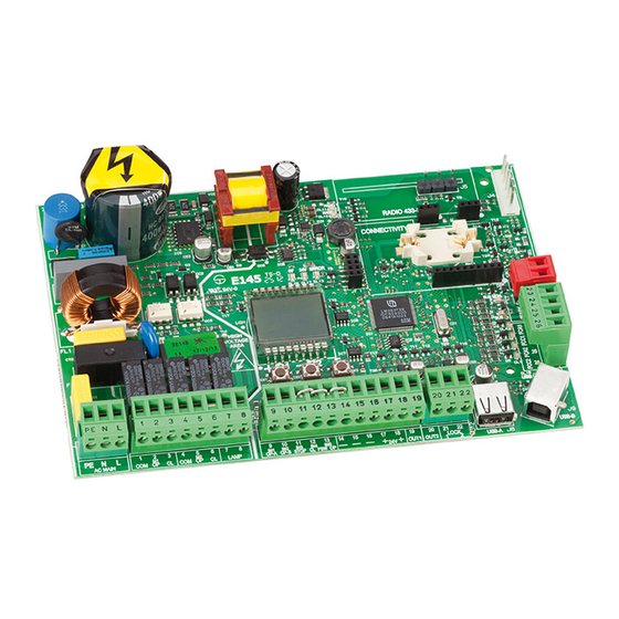
Page 6: Preparing For Installation
1 2 3 4 5 6 7 8 9 10 11 12 13 14 15 16 17 18 19 20 21 22 - - - LOCK LOCK OUT1 OUT2 USB-A AC MAIN LAMP OP-A OP-B STOP CL E145 732784 - Rev. A... - Page 7 WI-COM, Net-COM module DL13 “ERROR” Error/alarm signalling LED connector “BUS MON” BUS-2EASY diagnostic signalling BAT1 CR2032 buffer battery for board date/time DL14 Motor and power supply safety fuse DL15 Device signalling LED to BUS-2EASY ACTIVE E145 732784 - Rev. A...
-
Page 8: Electrical Connections
M2 - COM Common contact motor 2 of motor rotation, (see 5.4 TIME LEAR- M2 - OP Opening phase motor 2 NING - SETUP) M2 - CL Closing phase motor 2 LAMP Flashing lamp connection (MAX 60 W) E145 732784 - Rev. A... -
Page 9: J3 - Low-Voltage Accessories - Inputs/Outputs
OUT1 24 V " (Open Collector) programmable using function (advanced programming); default: always active. Other programming options are available by programming via a PC/MAC (see dedicated instructions). Fig. e.g.: Connecting 2 N.O. contacts in parallel. Fig. e.g.: Connecting 2 N.C. contacts in series. E145 732784 - Rev. A... -
Page 10: J12 - Programmable Outputs - Electric Locks
FCA1 GATECODER 1 FCC1 FCC1 FCA2 FCA2 GATECODER 2 FCC2 FCC2 FCA1 GATECODER 1 FCC1 FCA2 GATECODER 2 FCC2 FCA1, FCC1 and GATECODER1 correspond to LEAF 1; FCA2, FCC2 and GATECODER2 correspond to LEAF 2. E145 732784 - Rev. A... -
Page 11: J10 - Bus-2Easy
- suitable for protec- ting the entire movement area from risk of impact. Pulse generators: used as pulse generators for opening the automated system. Closing safety devices Opening safety devices E145 732784 - Rev. A... -
Page 12: Bus-2Easy
OPEN PULSE (1 pair) Connection of BUS-2EASY photocells For connecting you have to use two cables without polarity (see the specific device instructions). DL1 = Alignment DL2 = BUS-2EASY status/ Power supply DS1 = Programming Dip-switches 2EASY E145 732784 - Rev. A... -
Page 13: Bus-2Easy Encoder
Encoder Cable Inversion Note: by inverting the encoder wires, this will switch around the encoder associated with Encoder Encoder leaf 1 and the encoder associated with leaf 2 Leaf 1 Leaf 2 and vice versa. E145 732784 - Rev. A... -
Page 14: J5 - Xf Module Rapid Connector
MODULE RAPID CONNECTOR Plug-in connector dedicated to X-COM, G-COM, WI-COM, Net-COM modules. ALWAYS cut off power to the board BEFORE inserting/removing the module. Other programming options are available by programming via a PC/MAC (see dedicated instructions). E145 732784 - Rev. A... -
Page 15: Traditional Photocells
OP-A OP-B STOP CL FSW OP OP-A OP-B STOP CL FSW OP 9 10 11 12 13 14 15 16 17 18 19 20 21 22 9 10 11 12 13 14 15 16 17 18 19 20 21 22 E145 732784 - Rev. A... - Page 16 IN1 IN2 IN3 IN4 IN5 OUT1 OUT2 LK1 LK2 OP-A OP-B STOP CL FSW OP 9 10 11 12 13 14 15 16 17 18 19 20 21 22 Other RX CL TX CL safety devices E145 732784 - Rev. A...
- Page 17 9 10 11 12 13 14 15 16 17 18 19 20 21 22 9 10 11 12 13 14 15 16 17 18 19 20 21 22 Other RX OP TX OP RX CL TX CL safety devices TX OP/CL RX OP/CL E145 732784 - Rev. A...
-
Page 18: Programming
RELEASE THE KEYS THE FUNCTION VALUE THEN ALSO PROGRAMMING IS DISPLAYED THE FIRST FUNCTION APPEARS OTHERWISE SELECT TO EXIT THE PROGRAMMING WITHOUT SAVING +/R1 +/R1 THE FUNCTION IS DISPLAYED UNTIL YOU HOLD Tab. Programming phases. E145 732784 - Rev. A... -
Page 19: Basic Programming Functions
CLOSE inputs, these inputs will change to OPEN B. The simultaneous presence of CLOSE and OPEN B is possible only using the PC/MAC software. For a description of how the logics operate, see the related paragraph. E145 732784 - Rev. A... - Page 20 If a SETUP is performed with two motors and later only one is used, the board will not signal an error. Only the motor connected to input M1 will move. When programming from a PC/MAC, you can select different partial openings. E145 732784 - Rev. A...
- Page 21 = the limit switch determines the start of deceleration After having changed the value of this function, SETUP is required: the card will signal error (configuration error) until the SETUP is performed again or until the previous value is restored E145 732784 - Rev. A...
- Page 22 (separated by a decimal point) and time is adjusted in 10-second steps up to the maximum value of minutes. e.g.: if the display shows , the time is 1 min and 20 sec BUS-2EASY DEVICES ENTRY: See the related paragraph. E145 732784 - Rev. A...
- Page 23 WARNING If power is lost to the board prior to confirmation (step 2.), all changes made will be lost. You can EXIT programming at any time: press and hold F and then also - to switch directly to -/R2 E145 732784 - Rev. A...
-
Page 24: Advanced Programming Functions
= enabled (for 2 sec) = disabled In case of systems with an absolute encoder, to enable this function a setup must be performed using the automatic leaf stop on the mechanical contact point. E145 732784 - Rev. A... - Page 25 You can enable/disable the pre-flashing. Pre-flashing duration = 3 sec. You can choose: = disabled = pre-flashing before each movement = pre-flashing before a closing movement = pre-flashing before an opening movement = pre-flashing only at the end of the pause time E145 732784 - Rev. A...
- Page 26 ADDITIONAL OPERATING TIME (displayed only if function functions or = You can add a work time at the end of movement. Adjustable from sec in 1 sec steps. This time is not considered when calculating the deceleration per- centage. E145 732784 - Rev. A...
- Page 27 1-minute steps for functions 03-14 and from sec in 1-second steps for function 11 OUT 2: You can set the output OUT2 (open collector N.O.). See the options as OUT 2 TIMING (visualised only with the function Adjustable as for E145 732784 - Rev. A...
- Page 28 The value displayed is updated with the succession of the cycles, interacting with the value in When you can reset the cycle counter: press simultaneously and - for 5 sec. E145 732784 - Rev. A...
-
Page 29: Bus-2Easy
WARNING If power is lost to the board prior to confirmation (step 2.), all changes made will be lost. You can EXIT programming at any time: press and hold F and then also - to switch directly to -/R2 E145 732784 - Rev. A... -
Page 30: Device Installation
ON = correctly connected and entered OPEN photocell: ON = entered and engaged Closing photocells: ON = entered and engaged Fig. Visualising the BUS-2EASY status in the function : each segment of the display shows one type of device. E145 732784 - Rev. A... -
Page 31: Checking The Securing Devices Entered On The Board
- That there are no more than one device in the system with the same Rapid blinking (blink address. every 0.5 sec) - Calling error (number > or < the connected BUS devices). - FAIL SAFE error on the BUS device. Board in Sleep mode (if used). E145 732784 - Rev. A... -
Page 32: Time Learning - Setup
(the limit switch determines the stopping of motion) the OPEN A pulse for stopping motion is ignored. (the limit switch determines the start of deceleration) send an OPEN A pulse only after involving the opening limit switch. E145 732784 - Rev. A... -
Page 33: Testing The Automated System
Once installation and programming is completed, ensure that the system is operating correctly. Be especially careful that the safety devices operate correctly and ensure that the system complies with all current safety regulations. Close the cover in the provided seat with gasket. E145 732784 - Rev. A... -
Page 34: Memorising The Radio Code
Ensure that there are no obstacles (by people or things) during the automated system movement. OPEN A <5” 2” x 2 >5” >5” OPEN A TOTAL OPENING OPEN B <5” 2” x 2 >5” ” OPEN B PARTIAL OPENING E145 732784 - Rev. A... -
Page 35: Mhz)
6. When the 20 sec have elapsed, the LED will turn off, indicating that the procedure has been completed. 7. To add other radio controls, repeat the procedure from point 1. OPEN A >5” >5” >5” OPEN A TOTAL OPENING OPEN B >5” >5” ” OPEN B PARTIAL OPENING E145 732784 - Rev. A... -
Page 36: Remote Memorisation Of Lc/Rc Radio Controls
8. To add other radio controls with the same code, set the 12 dip-switches according to the same com- bination as the already memorised radio control. OPEN A >5” >5” DESIRED OPEN A CODE TOTAL OPENING OPEN B >5” ” DESIRED OPEN B CODE PARTIAL OPENING E145 732784 - Rev. A... -
Page 37: Deleting The Radio Controls
3. Once rapid flashing has stopped, LEDs DL11 and DL12 will go on steady, confirming the cancellation of all the radio codes (OPEN A and OPEN B/CLOSE) from the board memory. 4. Release -/R2 . The LEDs will go off, indicating correct cancellation. -/R2 E145 732784 - Rev. A... -
Page 38: Start-Up
Flashing simultaneously during DL2 FCA2 OPEN limit switch clear engaged movement of leaf 2. When the leaf is stationary, they can both CLOSE limit switch DL1 FCC2 CLOSE limit switch clear be either on or off engaged E145 732784 - Rev. A... -
Page 39: Signalling Errors And Alarms
Motor 2 encoder fault Check the connections or replace motor 2 encoder Incorrect memory data Repeat BUS-2EASY device entry and/or re-program the board Check that absorption by the accessories connected is within High absorption at +24V permitted limits E145 732784 - Rev. A... -
Page 40: Alarms
(only if the TIMER is operating) and replace the BAT1 - CR2032 buffer battery JOLLY TIMER is activated JOLLY TIMER is enabled by terminal board J3 TIMER DISABLED is operating TIMER is disabled by terminal board J3 E145 732784 - Rev. A... -
Page 41: Troubleshooting
• Check that the photocell wiring and alignment is correct • Check that there is no OPEN signal active The gate will not close • Check which function logic has been chosen (automatic or semi-automatic) E145 732784 - Rev. A... -
Page 42: Managing The Configuration File - J8 Usb
E145.prg E145.rad • E145SW.bin - The board SOFTWARE update file • E145.trm - The board TIMER update file • E145.prg - The board PROGRAMMING update file • E145.rad - The board RADIO update file These files will be generated, named and placed as shown in fig. in case of transfer from the board to the USB memory. - Page 43 E145.trm RADIO CODE LIST UPGRADE: This function lets you update the radio code list on the board (file E145.rad). If + and - are pressed simultaneously for at least 5 seconds, you will access the board update.
- Page 44 USB memory. = Copy: the radio codes file will be saved in the format E145.rad by overwriting any other radio codes file present with the same name, so it can be used to upgrade another system.
-
Page 45: Function Logics
E145 732784 - Rev. A... - Page 46 Logic with two separate An OPEN-A pulse During motion, the (OPEN-B commands: a held during closing opens, photocells reverse inputs become OPEN-A pulse opens; a CLOSE pulse during CLOSE) a held CLOSE pulse opening closes closes E145 732784 - Rev. A...
- Page 47 SAVES CLOSE if the cycle began with OPEN-B, opens totally operation can be modified by programming it opens if, at power up, an OPEN (A or B) command is active. Otherwise it closes. E145 732784 - Rev. A...
- Page 48 DISABLED if the cycle began with OPEN-B, opens totally operation can be modified by programming it opens if, at power up, an OPEN (A or B) command is active. Otherwise it closes. E145 732784 - Rev. A...
- Page 49 DISABLED if the cycle began with OPEN-B, opens totally operation can be modified by programming it opens if, at power up, an OPEN (A or B) command is active. Otherwise it closes. E145 732784 - Rev. A...
- Page 50 DISABLED if the cycle began with OPEN-B, opens totally operation can be modified by programming it opens if, at power up, an OPEN (A or B) command is active. Otherwise it closes. E145 732784 - Rev. A...
- Page 51 DISABLED if the cycle began with OPEN-B, opens totally operation can be modified by programming it opens if, at power up, an OPEN (A or B) command is active. Otherwise it closes. E145 732784 - Rev. A...
- Page 52 DISABLED if the cycle began with OPEN-B, opens totally operation can be modified by programming it opens if, at power up, an OPEN (A or B) command is active. Otherwise it closes. E145 732784 - Rev. A...
- Page 56 +33 4 72218700 tel. +1 904 4488952 tel. +971 42146733 www.faac.fr www.faacusa.com www.faac.ae FAAC FRANCE - AGENCE PARIS FAAC INTERNATIONAL INC Massy - Paris, France Fullerton, California - U.S.A. tel. +33 1 69191620 tel. +1 714 446 9800 www.faac.fr www.faacusa.com...
Need help?
Do you have a question about the E145 and is the answer not in the manual?
Questions and answers