FAAC E124 Quick Start Manual
Hide thumbs
Also See for E124:
- Original instructions manual (44 pages) ,
- Manual (32 pages) ,
- Rapid manual (25 pages)
Table of Contents
Advertisement
Advertisement
Table of Contents

Subscribe to Our Youtube Channel
Related Manuals for FAAC E124


Summary of Contents for FAAC E124
- Page 1 E124 Quick Start Guide...
-
Page 2: Table Of Contents
Signalling Errors and Alarms ............................10 Programming Remote Controls using the XF Receiver and OmniDec ................11 Programming a new remote control to a new E124 System ..................11 Programming a new remote control from a working master remote control ............11 Tutorial Videos available for programming remote controls .................. -
Page 3: Installation Sequence
L/N/E polarity on the plug 6. Power up the E124 Board (please note that the board will take 5-10 seconds to boot-up) 7. Verify the status of the LED’s and Display are as per Page 3 8. -
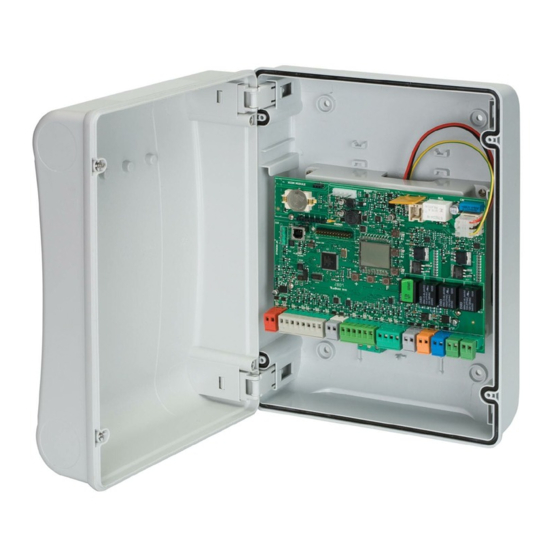
Page 4: Key Components Of E124 Board
Connection of Traditional Photocells The E124 Control Board allows for the use of traditional photocells (n/c with relay). Below is a layout drawing showing the basic positions normally covered. The wiring diagram is for Fail-Safe enabled photocells. In order to comply with the standards, all devices used for safety should either have a circuit monitored by the control board or be self-monitoring. -
Page 5: Connection Of Faac Bus 2Easy Photocells
Connection of FAAC BUS 2Easy Photocells The E124 Control Board also allows for the use of FAAC BUS 2easy photocells which allow for simpler cabling, a reduced power consumption, and Failsafe checking of each device independently. The Failsafe checking being performed by our proprietary FAAC BUS 2easy communication protocol also assist the installer by removing the need for separate cabling for a monitoring circuit. -
Page 6: Verification Of Bus 2Easy Connections On J10 Terminal
Verification of BUS 2easy Connections on J10 Terminal The J3 Terminal on the E124 Control Board has two diagnostic LED’s (DL15 – Red and DL14 – Green). These LED’s assist in ensuring that any devices connected on the FAAC BUS 2easy network are installed correctly. - Page 7 Please note that for the majority of systems the default power and speed settings will be sufficient to allow the first setup. These values will generally require further adjustments if force limitation is being used as part of the safety systems and a new setup should be run after the power settings are changed.
- Page 8 The below in the figure is what should be seen as an example for a double gate that is using encoders. Page | 7...
- Page 9 The above is the Status references is what will be seen under normal operation, even if the alarm LED is illuminated. To identify the error the signalling Errors and Alarms procedure should be followed. Page | 8...
-
Page 10: Advanced Programming Useful Functions
Advanced Programming useful functions The following parameters from Advanced Programming may also need to be changed if the SETUP continues to fail. The following shows the typical wiring of a Maglock using either OUT 1 or OUT 2 with a relay and separate power supply, which are configurable as per below in Advance Programming. -
Page 11: Signalling Errors And Alarms
Signalling Errors and Alarms Page | 10... -
Page 12: Programming Remote Controls Using The Xf Receiver And Omnidec
Tutorial Videos available for programming remote controls FAAC UK have created tutorial videos to assist the installer in the programming of remote controls. Please use the link below to navigate straight to our “YouTube” Channel or use your preferred web browser and navigate to “youTube.com” and search for “FAAC UK”...
Need help?
Do you have a question about the E124 and is the answer not in the manual?
Questions and answers