Endress+Hauser Liquiphant FTL33 IO-Link Operating Instructions Manual
Point level switch for liquids in the food sector
Hide thumbs
Also See for Liquiphant FTL33 IO-Link:
- Brief operating instructions (2 pages) ,
- Operating instructions manual (44 pages)

Related Manuals for Endress+Hauser Liquiphant FTL33 IO-Link


Summary of Contents for Endress+Hauser Liquiphant FTL33 IO-Link
-
Page 1: Operating Instructions
Products Solutions Services BA01934F/00/EN/02.18 71426392 2018-12-21 Operating Instructions Liquiphant FTL33 IO-Link Point level switch for liquids in the food sector... -
Page 2: Serial Number
Liquiphant FTL33 IO-Link Order code: XXXXX-XXXXXX Ser. no.: XXXXXXXXXXXX Ext. ord. cd.: XXX.XXXX.XX Serial number www.endress.com/deviceviewer Endress+Hauser Operations App A0023555 Endress+Hauser... -
Page 3: Table Of Contents
Liquiphant FTL33 IO-Link Table of contents Table of contents About this document ... 4 Commissioning ....30 Document function . -
Page 4: About This Document
About this document Liquiphant FTL33 IO-Link About this document Document function These Operating Instructions contain all the information that is required in various phases of the life cycle of the device: from product identification, incoming acceptance and storage, to mounting, connection, operation and commissioning through to troubleshooting, maintenance and disposal. - Page 5 Liquiphant FTL33 IO-Link About this document Symbol Meaning Reference to documentation Reference to page Reference to graphic Notice or individual step to be observed … Series of steps Result of a step Help in the event of a problem Visual inspection 1.2.4...
-
Page 6: Documentation
• W@M Device Viewer (www.endress.com/deviceviewer): Enter the serial number from nameplate • Endress+Hauser Operations App: Enter the serial number from the nameplate or scan the 2D matrix code (QR code) on the nameplate 1.3.1 Technical Information (TI): planning aid for your device The document contains all the technical data on the device and provides an overview of the accessories and other products that can be ordered for the device. -
Page 7: Basic Safety Instructions
Liquiphant FTL33 IO-Link Basic safety instructions Basic safety instructions Requirements for personnel The personnel for installation, commissioning, diagnostics and maintenance must fulfill the following requirements: • Trained, qualified specialists must have a relevant qualification for this specific function and task •... -
Page 8: Operational Safety
Basic safety instructions Liquiphant FTL33 IO-Link Operational safety Risk of injury! ‣ Operate the device in proper technical condition and fail-safe condition only. ‣ The operator is responsible for the interference-free operation of the device. Product safety This measuring device is designed in accordance with good engineering practice to meet state- of-the-art safety requirements, has been tested, and left the factory in a condition in which it is safe to operate. -
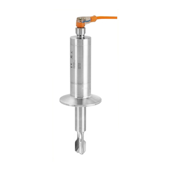
Page 9: Product Description
150 °C (302 °F) for process temperatures up to: Sensor type Compact version Short tube version For detailed information on the short tube version and the process connections, see "Technical Information". Available in Downloads area of the Endress+Hauser website (www.endress.com/downloads). Endress+Hauser... -
Page 10: Incoming Acceptance And Product Identification
‣ Enter the serial number from the nameplate into the Endress+Hauser Operations App or use the Endress+Hauser Operations App to scan the 2-D matrix code (QR Code) provided on the nameplate All the information about the measuring device and the scope of the associated Technical Documentation are displayed. - Page 11 Liquiphant FTL33 IO-Link Incoming acceptance and product identification 4.4.3 Handling of the device NOTICE Risk of injury! Housing or fork may become damaged or tear! ‣ Transport the device to the measuring point in its original packaging or by the housing.
-
Page 12: Installation
Installation Liquiphant FTL33 IO-Link Installation Installation conditions 5.1.1 Orientation Installation is possible in any position in a vessel, pipe or tank. A0036961 3 Installation examples Overfill prevention or upper level detection (maximum safety) Dry running protection for pump (minimum safety) - Page 13 Liquiphant FTL33 IO-Link Installation 5.1.2 Switch point The switch point (A) on the sensor depends on the orientation of the point level switch (water +25 °C (+77 °F), 1 bar (14.5 psi). Configuration is possible via IO-Link. A0020734 4 Vertical and horizontal orientation, dimensions in mm (in) 5.1.3...
- Page 14 Installation Liquiphant FTL33 IO-Link 5.1.4 Buildup Make sure that the installation socket does not exceed a certain length so that the tuning fork can project freely into the vessel. Possibilities for optimization: • A vertical orientation of the point level switch keeps buildup to a minimum.
- Page 15 Liquiphant FTL33 IO-Link Installation 5.1.6 Marking The marking indicates the position of the tuning fork. If installed horizontally in vessels, the marking is face up. The marking appears either as a material specification (e.g. 316L) or a thread designation (e.g. G ½") in the following locations: •...
- Page 16 Installation Liquiphant FTL33 IO-Link 5.1.7 Installation in pipes During installation, pay attention to the position of the fork in order to minimize turbulence in the pipe. G 3/4 316L <5 m/s (16 ft/s) A0021357 Dimensions mm (in) Endress+Hauser...
- Page 17 Liquiphant FTL33 IO-Link Installation 5.1.8 Installation in vessels If installed horizontally, pay attention to the position of the tuning fork to ensure that the liquid can drip off. The electrical connection, e.g. M12 connector, should be pointing down with the cable. This can prevent moisture from penetrating.
-
Page 18: Mounting The Measuring Device
Installation Liquiphant FTL33 IO-Link Mounting the measuring device Use in accordance with WHG: Prior to mounting the device, pay attention to the WHG approval documents. Documents available in the Downloads area of the Endress+Hauser website: www.endress.com → Downloads 5.2.1 Required tools "Weld-in adapter accessories"... -
Page 19: Post-Installation Check
Liquiphant FTL33 IO-Link Installation Metric thread in customer nozzle 66.4 (2.6) 47.9 (1.8) 32 mm A0022026 11 Metric thread in customer nozzle G 1" Pressure and temperature (maximum): +40 bar (+580 psi) at 150 °C (302 °F) NPT thread (ANSI B 1.20.1) -
Page 20: Electrical Connection
Electrical connection Liquiphant FTL33 IO-Link Does the device comply with the measuring point specifications? • Process temperature • Process pressure • Ambient temperature range • Switch point/measuring range Are the measuring point identification and labeling correct (visual inspection)? Is the device adequately protected against moisture and direct sunlight? Is the device adequately protected against impact? -
Page 21: Connecting The Device
Liquiphant FTL33 IO-Link Electrical connection Connecting the device WARNING Risk of injury from the uncontrolled activation of processes! ‣ Switch off the supply voltage before connecting the device. ‣ Make sure that downstream processes are not started unintentionally. WARNING Electrical safety is compromised by an incorrect connection! ‣... -
Page 22: Post-Connection Check
Electrical connection Liquiphant FTL33 IO-Link Maximum safety Terminal assignment MAX output LED yellow (ye) 2 A0037918 – Function monitoring When both outputs are connected, the MIN and MAX outputs assume opposite states (XOR) when the device is operating fault-free. In the event of an alarm condition or a cable break, both outputs are de-energized. -
Page 23: Operation Options
Liquiphant FTL33 IO-Link Operation options Operation options Operation with an operating menu 7.1.1 IO-Link information IO-Link is a point-to-point connection for communication between the measuring device and an IO-Link master. The measuring device features an IO-Link communication interface type 2 with a second IO function on pin 4. -
Page 24: Overview Of The Operating
Overview of the operating menu Liquiphant FTL33 IO-Link Overview of the operating menu Depending on the parameter configuration, not all submenus and parameters are available. Information on this can be found in the parameter description under "Prerequisite". IO-Link Level 1... - Page 25 Liquiphant FTL33 IO-Link Overview of the operating menu IO-Link Level 1 Level 2 Switching delay time, Output 2 (dS2) Switchback delay time, Output 2 (dR2) Output 2 (OU2) System Operating hours µC-Temperature Unit changeover (UNI) - µC-Temperature Minimum µC-Temperature Maximum µC-Temperature Reset µC temperatures [button]...
-
Page 26: System Integration
System integration Liquiphant FTL33 IO-Link System integration Process data The FTL3x devices can be configured with one or two switch outputs. The status of the switch output is transmitted in the form of process data via IO-Link. • In the SIO mode, switch output 1 is switched at pin 4 of the M12 plug. In the IO-Link communication mode, this pin is reserved exclusively for communication. - Page 27 Liquiphant FTL33 IO-Link System integration Designation ISDU ISDU Size Data type Access Default Value range Offset / Data Range (dec) (hex) (byte) value Gradient storage limits Simulation 0x0059 1 UInt8 0~off 0 ~ off 0 / 0 0..2 Switch Output...
- Page 28 System integration Liquiphant FTL33 IO-Link Designation ISDU ISDU Size Data type Access Default Value range Offset / Data Range (dec) (hex) (byte) value Gradient storage limits Active 0x004D 1 UInt8 0 ~ Density 0..2 switchpoints Density >0.7g/cm³ (OU2) >0.7g/c 1 ~ Density >0.5g/cm³...
- Page 29 Liquiphant FTL33 IO-Link System integration Designation ISDU ISDU Size Data type Access Default Value range Offset / Data Range (dec) (hex) (byte) value Gradient storage limits Minimum µC- 0x005C 1 Int16 °C: 0 / 1 −32768 .. Temperature °°F: 32 / 32767 273.15 /...
-
Page 30: Commissioning
Commissioning Liquiphant FTL33 IO-Link Designation ISDU (dec) ISDU (hex) Size (byte) Data type Access Default value Data storage Application Specific 0x0018 String Actual Diagnostics 0x0104 String (STA) Last Diagnostic (LST) 0x0105 String 9.2.3 System commands Designation ISDU (dec) ISDU (hex) -
Page 31: Commissioning The Local Display
Liquiphant FTL33 IO-Link Commissioning 10.2 Commissioning the local display 10.2.1 Light signals (LEDs) Position of LEDs in housing cover A0037920 Position LED color Description of function Status/Communication • lit: SIO mode green (gn) • flashing: Active communication, flash frequency • flashes with increased luminosity: Device search (device identification), flash frequency Warning/Maintenance required flashing: Error remediable, e. g. - Page 32 Commissioning Liquiphant FTL33 IO-Link LEDs on housing cover with M12 connector, IO-Link Operating modes Warning Fault Sensor free covered free covered A0037920 1: green (gn) 2: red (rd) 3: yellow (ye) 2 4: yellow (ye) 1 LEDs on M12 connector (signals status of switch outputs)
-
Page 33: Function Test With Test Magnet
Liquiphant FTL33 IO-Link Commissioning 10.3 Function test with test magnet WARNING Risk of injury! ‣ Ensure that no dangerous processes are triggered in the system. To perform a function test, hold the test magnet against the marking on the nameplate (for at least 2 seconds). -
Page 34: Customer-Specific Io-Link
Customer-specific IO-Link settings Liquiphant FTL33 IO-Link IO-Link communication • Commissioning with factory settings: The device is configured for use with water-based media. The device can be commissioned directly when used with water-based media. Factory setting: output 1 and output 2 are configured for XOR operation. -
Page 35: Diagnostics And Troubleshooting
Liquiphant FTL33 IO-Link Diagnostics and troubleshooting Diagnostics and troubleshooting 12.1 Troubleshooting If an electronic/sensor defect is present, the device changes to the error mode and displays the diagnostic event F270. Diagnostic message issued via IO-Link as well as status LEDs on device. -
Page 36: Diagnostic Events
Diagnostics and troubleshooting Liquiphant FTL33 IO-Link 12.3 Diagnostic events 12.3.1 Diagnostic message Faults that are detected by the device' s self-monitoring system are displayed as a diagnostic message via IO-Link. Status signals The table lists the messages that may occur. The Actual Diagnostic (STA) parameter displays the message with the highest priority. -
Page 37: Overview Of Diagnostic Events
Liquiphant FTL33 IO-Link Diagnostics and troubleshooting 12.4 Overview of diagnostic events Status Diagnostic EventCode Event text Cause Corrective measure signal/ behavior Diagnostic event F270 IO-Link error 0x5000 Defect in electronics/ Defect in Replace device sensor electronics/sensor S804 IO-Link warning 0x1801 Load current >... -
Page 38: Fault
Maintenance Liquiphant FTL33 IO-Link message, the device behaves as per a warning or fault condition. It is necessary to distinguish between the following types of errors here: • Warning: – The device continues measuring if this type of error occurs. The output signal is not affected (exception: simulation is active). -
Page 39: Repair
The measuring device must be returned if it is in need of repair or a factory calibration, or if the wrong measuring device has been delivered or ordered. Legal specifications require Endress+Hauser, as an ISO-certified company, to follow certain procedures when handling products that are in contact with the medium. -
Page 40: Description Of Device
Description of device parameters Liquiphant FTL33 IO-Link Description of device parameters 15.1 Diagnosis Actual Diagnostics (STA) Navigation Diagnosis → Actual Diagnostics (STA) Description Displays the current device status. Last Diagnostic (LST) Navigation Diagnosis → Last Diagnostic (LST) Description Displays the latest device status (error or warning) that was rectified during operation. - Page 41 Liquiphant FTL33 IO-Link Description of device parameters Navigation Diagnosis → Simulation Switch Output 2 (OU2) Description The simulation affects the process data and the physical switch output. If a simulation is active, a warning to this effect is displayed via IO-Link so that it is obvious to the user that the device is in the simulation mode (C485 - simulation active).
- Page 42 Description of device parameters Liquiphant FTL33 IO-Link Description This parameter is used to test if the measuring point is functioning correctly. The sensor must not be covered and must be free of residue. The device compares the current measured values with the measured values from the factory adjustment.
-
Page 43: Parameters
Liquiphant FTL33 IO-Link Description of device parameters 15.2 Parameters 15.2.1 Application Active switchpoints Navigation Application → Active switchpoints Description Choose from standard (0.7 / 0.5 g/cm ) or customer- specific, user-definable switch points Switch-on value Last setting selected prior to switching off device. - Page 44 Description of device parameters Liquiphant FTL33 IO-Link Navigation Application → Switch point value, Output 1/2 (SP1/SP2) Application → Switchback point value, Output 1/2 (rP1/ rP2) Note The switching sensitivity of the sensor is set using the SP1/rP1 or SP2/rP2 parameters. Since the parameter settings depend on one another, the parameters are described all together.
- Page 45 Liquiphant FTL33 IO-Link Description of device parameters HNO (MIN) HNC (MAX) A0037934 0-signal, output open 1-signal, output closed Hysteresis (difference between the value of the switch point SP1/SP2 and the value of the switchback point rP1/rP2) Fork frequency (100 % corresponds to frequency in air / uncovered)
- Page 46 Description of device parameters Liquiphant FTL33 IO-Link FNC (MAX) FNO (MIN) A0037950 0-signal, output open 1-signal, output closed Window Fork frequency (100 % corresponds to frequency in air / uncovered) FNO Normally open contact (MIN) FNC Normally closed contact (MAX)
- Page 47 Liquiphant FTL33 IO-Link Description of device parameters Navigation Application → Switch output → Switching delay time, Output 1/2 (dS1/dS2) Application → Switch output → Switchback delay time, Output 1/2 (dR1/dR2) Note The switching delay time/switchback delay time functions are implemented using the "dS1"/"dS2" and "dR1"/dR2"...
-
Page 48: Input Range
Description of device parameters Liquiphant FTL33 IO-Link HNO (MIN) HNC (MAX) A0034590 0-signal, output open in the quiescent state 1-signal, output closed in the quiescent state Hysteresis (difference between the value of the switch point "SP1" and the value of the switchback point "rP1") - Page 49 Liquiphant FTL33 IO-Link Description of device parameters Description • Hysteresis: Determining whether sensor is free or covered. • Window: Determining medium Setting is medium-specific in each case. – SP1/rP1 = medium 1 – SP2/rP2 = medium 2 Switch on value Last function selected prior to switching off.
- Page 50 Description of device parameters Liquiphant FTL33 IO-Link Description This parameter is used to select the electronics temperature unit. Once a new electronics temperature unit has been selected, the new unit is calculated and displayed. Switch on value Last unit selected prior to switching off.
- Page 51 Liquiphant FTL33 IO-Link Description of device parameters Reset to factory settings (RES) Navigation System → Reset to factory settings (RES) Description WARNING Confirming the "Standard Command" with "Reset to factory settings" causes an immediate reset to the factory settings of the order configuration.
-
Page 52: Observation
15.3 Observation The process data are transmitted acyclically. Accessories For detailed information on accessories, see "Technical Information" for weld-in adapters, process adapters and flanges Available in Downloads area of the Endress+Hauser website (www.endress.com/downloads). Designation Additional information Weld-in adapter For detailed information on weld-in adapters, see supplementary documentation. -
Page 53: Technical Data
• IP66/68 NEMA Type 4X/6P Enclosure (cable) Electromagnetic compatibility Electromagnetic compatibility in accordance with all the relevant requirements of the EN 61326 series. For details, refer to the EC Declaration of Conformity. Available in the Download Area of the Endress+Hauser website: www.endress.com. Endress+Hauser... - Page 54 Technical data Liquiphant FTL33 IO-Link 17.2.1 Derating [°F] [°C] +158 +122 –40 –40 [°C] –40 +100 [°F] –40 +122 +212 +176 A0022002 14 Derating curve: 100 °C (212 °F) : 200 mA (DC-PNP), 250 mA (AC/DC) : 150 mA (DC-PNP), 150 mA (AC/DC)
-
Page 55: Process
Liquiphant FTL33 IO-Link Technical data [°F] [°C] +158 +122 –40 –40 [°C] –40 +100 +150 [°F] –40 +122 +212 +302 +194 A0020869 15 Derating curve: 150 °C (302 °F) : 200 mA (DC-PNP), 250 mA (AC/DC) : 150 mA (DC-PNP), 150 mA (AC/DC) - Page 56 *71426392* 71426392 www.addresses.endress.com...
Need help?
Do you have a question about the Liquiphant FTL33 IO-Link and is the answer not in the manual?
Questions and answers