Endress+Hauser Liquiphant FTL31 Operating Instructions Manual
Point level switch for liquids
Hide thumbs
Also See for Liquiphant FTL31:
- Manual (32 pages) ,
- Operating instructions manual (56 pages)

Related Manuals for Endress+Hauser Liquiphant FTL31


Summary of Contents for Endress+Hauser Liquiphant FTL31
- Page 1 Products Solutions Services BA01285F/00/EN/03.22-00 71578503 2022-07-12 Operating Instructions Liquiphant FTL31 Point level switch for liquids...
- Page 2 Liquiphant FTL31 Order code: XXXXX-XXXXXX Ser. no.: XXXXXXXXXXXX Ext. ord. cd.: XXX.XXXX.XX Serial number www.endress.com/deviceviewer Endress+Hauser Operations App A0023555 Endress+Hauser...
-
Page 3: Table Of Contents
Liquiphant FTL31 Table of contents Table of contents Document information ..4 Repair ......34 Document function . -
Page 4: Document Information
Document information Liquiphant FTL31 Document information Document function These Operating Instructions contain all the information that is required in various phases of the life cycle of the device: from product identification, incoming acceptance and storage, to mounting, connection, operation and commissioning through to troubleshooting, maintenance and disposal. -
Page 5: Documentation
Symbol Meaning Open-ended wrench A0011222 Documentation The document types listed are available in the Download Area of the Endress+Hauser website: www.endress.com → Download Document Purpose and content of the document Technical Information This document contains all the technical data for the device and provides an overview of TI01147F/00/EN the accessories that can be ordered. -
Page 6: Basic Safety Instructions
Basic safety instructions Liquiphant FTL31 Basic safety instructions Requirements for the personnel The personnel performing installation, commissioning, diagnostics and maintenance must satisfy the following requirements: • Trained, qualified specialists: must have a relevant qualification for this specific function and task •... -
Page 7: Operational Safety
It meets the general safety standards and legal requirements. It also complies with the EC directives listed in the device-specific EC Declaration of Conformity. Endress+Hauser confirms this by affixing the CE mark to the device. Endress+Hauser... -
Page 8: Product Description
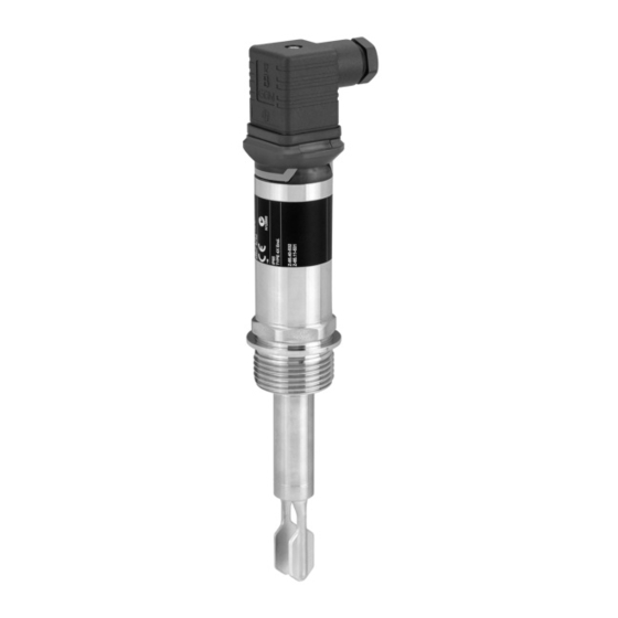
Product description Liquiphant FTL31 Product description The Liquiphant FTL31 is a point level switch for universal use in all liquids. It is used preferably in storage tanks, mixing vessels and pipes. Product design The point level switch is available in different versions, which can be assembled in accordance with user specifications. -
Page 9: Incoming Acceptance And Product Identification
‣ Enter the serial number from the nameplate into the Endress+Hauser Operations App or use the Endress+Hauser Operations App to scan the 2-D matrix code (QR Code) provided on the nameplate All the information about the measuring device and the scope of the associated Technical Documentation are displayed. - Page 10 Incoming acceptance and product identification Liquiphant FTL31 4.4.3 Handling of the device NOTICE Risk of injury! Housing or fork may become damaged or tear! ‣ Transport the device to the measuring point in its original packaging or by the housing.
-
Page 11: Mounting
Liquiphant FTL31 Mounting Mounting Mounting requirements 5.1.1 Orientation Installation is possible in any position in a vessel, pipe or tank. A0036961 2 Installation examples Overfill prevention or upper level detection (maximum safety) Dry running protection for pump (minimum safety) Lower level detection (minimum safety) 5.1.2... - Page 12 Mounting Liquiphant FTL31 • If installing in vessels with high-viscosity liquids (A), the tuning fork may not be located in the installation socket! • If installing in vessels with low-viscosity liquids (B), the tuning fork may be located in the installation socket.
- Page 13 Liquiphant FTL31 Mounting A0022057 5 Buildup on tank wall, pipe wall and tuning fork 5.1.5 Weld-in adapter with leakage hole If installed horizontally, make sure that the leakage hole is pointing down. This allows leaks to be detected as quickly as possible.
- Page 14 Mounting Liquiphant FTL31 <-1.4435 <-1.4435 <-1.4435 ± 15° A0022641 6 Orientation in the vessel ±15° A0022804 7 Orientation in the pipe 5.1.7 Installation in pipes During installation, pay attention to the position of the fork in order to minimize turbulence in the pipe.
- Page 15 Liquiphant FTL31 Mounting <5 m/s (16 ft/s) A0021357 8 Position of the tuning fork in pipes. Unit of measurement mm (in) 5.1.8 Installation in vessels If installed horizontally, pay attention to the position of the tuning fork to ensure that the liquid can drip off.
-
Page 16: Mounting The Measuring Device
Mounting Liquiphant FTL31 A0022272 Mounting the measuring device Use in accordance with WHG: Prior to mounting the device, pay attention to the WHG approval documents. The documents can be found in the Download Area of the Endress +Hauser website: www.endress.com → download 5.2.1... -
Page 17: Post-Mounting Check
Liquiphant FTL31 Mounting View, dimensions in mm (in) Description Metric thread in customer nozzle 66.4 (2.6) Example G 1" 47.9 (1.8) Pressure and temperature (maximum): 32 mm +40 bar (+580 psi) at 150 °C (302 °F) A0022026 NPT thread (ANSI B 1.20.1) -
Page 18: Electrical Connection
Electrical connection Liquiphant FTL31 Electrical connection The device has two operating modes: maximum safety (MAX) and minimum safety (MIN). By choosing the corresponding operating mode, the user ensures that the device also switches in a safety-oriented manner even in an alarm condition, e.g. if the power supply line is disconnected. - Page 19 Liquiphant FTL31 Electrical connection Maximum safety Terminal assignment MAX output Yellow LED (ye) 0.5A L– Wire colors for M12 plug: • 1 = BN (brown) • 2 = WT (white) • 3 = BU (blue) • 4 = BK (black)
- Page 20 Electrical connection Liquiphant FTL31 When both outputs are connected, the MIN and MAX outputs assume opposite states (XOR) when the device is operating fault-free. In the event of an alarm condition or a line break, both outputs are de-energized. Connection for function monitoring using XOR operation...
- Page 21 Liquiphant FTL31 Electrical connection A0022900 11 Valve plug 3-wire DC-PNP Terminal assignment MAX operating mode Yellow LED (ye) – 0.5A L– Symbols Description Yellow LED (ye) lit Yellow LED (ye) not lit External load 3-wire DC-PNP Terminal assignment MIN operating mode Yellow LED (ye) –...
- Page 22 Electrical connection Liquiphant FTL31 A0022902 12 Cable (cannot be disassembled) 3-wire DC-PNP Terminal assignment MAX operating mode Yellow LED (ye) 0.5A L– L+ Wire colors: 1 = BK (black) 2 = GR (gray) 3 = BN (brown) Ground = GNYE (green-yellow)
- Page 23 Liquiphant FTL31 Electrical connection 3-wire DC-PNP Terminal assignment MIN operating mode Yellow LED (ye) Wire colors: 1 = BK (black) 2 = GR (gray) 3 = BN (brown) Ground = GNYE (green-yellow) Symbols Description Yellow LED (ye) lit Yellow LED (ye) not lit...
- Page 24 Electrical connection Liquiphant FTL31 6.1.2 Electronic version 2-wire AC/DC The load is switched via an electronic switch directly in the power supply circuit. Always connect in series with a load! Not suitable for connection to low-voltage PLC inputs! Selection tool for relays...
- Page 25 Liquiphant FTL31 Electrical connection P2: DC mode Relay operating voltage: Relay rated power • 24 V: 0.7 to 6 W • 48 V: 0.9 to 12 W • 60 V: 1.5 to 15 W Relays with a lower rated power can be operated by means of an RC module connected in parallel (optional).
- Page 26 Electrical connection Liquiphant FTL31 2-wire AC/DC Terminal assignment MIN operating mode Yellow LED (ye) A0045070 >20 V 0.5A A0045069 L1/L+ N/L– A0021220 Symbols Description Yellow LED (ye) lit Yellow LED (ye) not lit External load Connection with cable Depending on the assignment of the connector or the wiring of the cable, the device works in either the MAX or MIN operating mode.
-
Page 27: Post-Connection Check
Liquiphant FTL31 Electrical connection 2-wire AC/DC Terminal assignment MAX operating mode Yellow LED (ye) A0045072 >20 V 0.5A A0045074 L1/L+ N/L– A0022161 Wire colors: 1 = BK (black) 2 = GR (gray) 3 = BN (brown) Ground = GNYE (green-yellow) - Page 28 Electrical connection Liquiphant FTL31 Does the supply voltage match the specifications on the nameplate? Do the cables used comply with the requirements? Do the mounted cables have adequate strain relief? Are the cable glands mounted and firmly tightened? ...
-
Page 29: Commissioning
Liquiphant FTL31 Commissioning Commissioning Function check Go through the following checklists before commissioning: • "Post-installation check" checklist • "Post-connection check" checklist The function of the tuning fork can be tested by immersing the tuning fork in a vessel containing water. - Page 30 Commissioning Liquiphant FTL31 Function Description LED red (rd) Warning/maintenance required: error can be rectified, e.g. incorrect wiring; protective function if Flashing test magnet is held against the sensor for longer than 30 s LED red (rd) Fault/device failure: error cannot be rectified, e.g. electronic error On the metal housing cover (IP69), there is no external signaling via LEDs.
-
Page 31: Function Of Leds
Liquiphant FTL31 Commissioning Function of LEDs Operating modes Connection Maximum safety (MAX) Minimum safety (MIN) Warning Fault A0023004 A0023007 A0023009 A0023003 A0023005 A0023006 A0023008 1: Level display not lit 2: M12 plug lit 3: Valve plug flashing 4: Cable ... - Page 32 Commissioning Liquiphant FTL31 A0020960 16 Position for test magnet on housing Endress+Hauser...
-
Page 33: Diagnostics And Troubleshooting
Liquiphant FTL31 Diagnostics and troubleshooting Diagnostics and troubleshooting Diagnostic information via LED display LED display on housing cover Malfunction Possible cause Corrective action Green LED Check connector, cable and power supply No power supply Not lit Red LED Overload or short-circuit in •... -
Page 34: Repair
(WEEE), our products are marked with the depicted symbol in order to minimize the disposal of WEEE as unsorted municipal waste. Such products may not be disposed of as unsorted municipal waste and can be returned to Endress+Hauser for disposal at conditions stipulated in our General Terms and Conditions or as individually agreed. - Page 35 Liquiphant FTL31 Accessories Designation Additional information Plug-in jack M12 • IP69K, coupling nut 316L with cable 5 m (16 ft) • Angled with LED, order number: 52018763 • Angled without LED, order number: 52024216 • IP67, coupling nut (Cu Sn/Ni) •...
-
Page 36: Technical Data
Technical data Liquiphant FTL31 Technical data For additional information on the technical data, see the Technical Documentation TI01147F/00/EN. 12.1 Power supply Electronic version Supply voltage Power consumption Current consumption 3-wire DC-PNP 10 to 30 V DC < 975 mW < 15 mA... - Page 37 Electromagnetic compatibility Electromagnetic compatibility in accordance with all relevant requirements of the EN 61326 series and NAMUR recommendation EMC (NE21). For details, refer to the EC Declaration of Conformity. Available in the Download Area of the Endress+Hauser website: www.endress.com. 12.2.1 Derating [°F]...
-
Page 38: Process
Technical data Liquiphant FTL31 [°F] [°C] +158 +122 –40 –40 [°C] –20 +100 +150 [°F] –4 +122 +212 +302 +194 A0020869 18 Derating curve: 150 °C (302 °F) : 200 mA (DC-PNP), 250 mA (AC/DC) : 150 mA (DC-PNP), 150 mA (AC/DC) - Page 40 *71578503* 71578503 www.addresses.endress.com...
Need help?
Do you have a question about the Liquiphant FTL31 and is the answer not in the manual?
Questions and answers