
Related Manuals for Redman Power Chair CHIEF 107 SERIES

Summary of Contents for Redman Power Chair CHIEF 107 SERIES
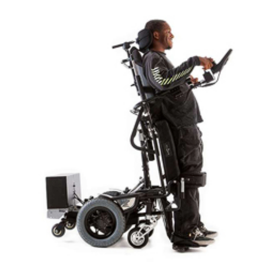
- Page 1 Volume SERIES 107 POWERED WHEELCHAIR, STANDARD EQUIPMENT ____________________________________________________________________________________________ CHIEF 107 SERIES Owner, Operator & Maintenance Manual...
- Page 2 D I S T R I B U T E D B Y M E D I - C H A I R L L C Manufactured by Chief Power Chair LLC Medi-Chair LLC 1601 S. Pantano Rd. #107 Tucson, AZ 85710-6791 www.redmanpowerchair.com Customer Service Toll Free: (800) 727- 6684 (ext 2)
-
Page 3: Table Of Contents
Table of Contents Disclaimer ........................X Introduction........................1 Operation ........................2 General Care ........................4 Tires ..........................8 Batteries ........................... 9 Troubleshooting ......................13 Mechanical ......................14 Body Positioning ....................15 Joystick Wiring ....................... 15 Power Module ......................16 Motors ........................... 17 Adjustments ........................ - Page 4 Series 107 power wheelchair, property and/or injury to the user. Please ensure proper use by following the directions below: Before using a Redman Power Chair be sure to fully understand the training representative’s instructions, and that you have also received the operation manual and delivery documentation.
-
Page 5: Disclaimer
Series 107 power wheelchair are not intended to serve as a body restraining system in a moving motor vehicle. When traveling in a motor vehicle, Redman Power Chair recommends transferring the user to the occupant seating and restraining system approved for that motor vehicle. -
Page 6: Introduction
Redman Power Chair takes pride in the quality of our product. We are the innovator of standing power wheelchairs for over 30 years. This is not just a standing chair but a life changing body positioning system. -
Page 7: Operation
Section R E D M A N P O W E R C H A I R Operation Understanding the basic components of the major operation system can be beneficial when properly handling and maintaining your system. One of the two major components is the joystick controller which is connected to the power module through a communication cable. - Page 8 R E D M A N P O W E R C H A I R Mode The Mode button may be pressed to go back and forth from the “drive” screen and the “positioning” screen (shown in Figure 2). After pressing the Mode button, you will view the body positioning screens shown in three of the images in Figure 2.
-
Page 9: General Care
Section R E D M A N P O W E R C H A I R General Care This manual includes maintenance and operational directions which mandate your safety and protection. Failure to read and follow the operational instructions in this manual could not only result in injury to yourself and others, but to the product and/ or property as well. -
Page 10: Daily Checks
R E D M A N P O W E R C H A I R Daily Checks Two important daily checks, besides performing a daily visual inspection of your RPC (Redman Power Chair), concern the batteries and joystick. Be sure to: o Charge your chair’s batteries daily. - Page 11 Other Recommended Care & Maintenance Apart from daily and weekly maintenance there are some recommended service procedures that may be performed based on your discretion and usage as the owner of a Redman Power Chair. Lubrication Points The arrows in Figure 3 indicate the lubrication points. Keep your chair clean and free of dirt and debris, paying special attention to moving parts and pivot points.
- Page 12 Periodic adjustment of tipper fork bearings is recommended but not pictured as a part of this maintenance manual. Please contact Redman Power Chair for further instructions on how to complete this task. Figure 6...
-
Page 13: Tires
Section Tires If your chair is equipped with inflatable tires, check tire pressure monthly to confirm that tires are inflated to the proper pressure. Keep the following points in mind: 12” x 3” drive tires, not to exceed 35 psi. 12”... -
Page 14: Batteries
Section Batteries Redman Power Wheelchairs are installed with MK sealed VRLA gel batteries. All information necessary for troubleshooting the batteries can be found on the MK website (http://www.mkbattery.com) and at http://www.mkbattery.com/documents/5646MK_HME_BCG_v7r3.pdf for the Battery Care Maintenance Guide. The following are steps encouraged/recommended by MK Battery to safely use, maintain, charge, and care for your batteries: "Battery Care and Maintenance Guide."... - Page 15 "Battery Care and Maintenance Guide." www.mkbattery.com, sales@mkbattery.com. Accessed 2018.
- Page 16 Battery Box Location & Removal Redman Power Wheelchairs equipped with standard 12 volt group 22 batteries. Reference Figure 8 for the placement of batteries on a Redman Power Wheelchair. Figure 8 The image to the left (Figure 9) references the battery box screw locations.
- Page 17 Battery Wiring This section will describe the battery wiring of a Redman Power Chair. It is designed to accommodate technicians and customers changing out batteries. We recommend focus on one battery at a time. These adjustments are provided only as a reference for an...
-
Page 18: Troubleshooting
Section Troubleshooting Hard Reset The Redman Power Wheelchair is equipped with a master circuit breaker located on the front of the battery box. The 90 amp circuit breaker can be manually reset by following the directions below: Pull the black circular breaker button (marked with the number 90 to the “OUT” position). -
Page 19: Mechanical
Optional accessories, such as an automotive horn and 12-volt auxiliary outlet are connected to the batteries with separately fused circuits. Please check the fuses if you are experiencing any problems with these accessories. The fuses are located on the exterior of the battery box along with the circuit breaker. -
Page 20: Body Positioning
Body Positioning Troubleshooting Body positioning control components are located under the power chair. (In the event of a motor power failure, check to make sure connections are tight). The ISM (Intelligent Seating Mechanism) controls the actuators for positioning of your chair. If the chair will not stand or positioning systems fail, try a hard reset by disconnecting the main power at the circuit breaker. -
Page 21: Power Module
Section Power Module The power module location varies depending on the size of each individual chair. The ISM, motors, batteries, and stand actuator safety switch are all plugged into this device. Figure 18 As numbered left to right: 1. ISM, 2. Left motor, 3. Batteries, 4. Right motor, 5. Stand actuator safety switch... -
Page 22: Motors
Section Motors Your power wheelchair can be free-wheeled by turning the yellow motor levers. It will be easier to reach the levers if the chair is placed in standing a position. o If the levers are vertical, the motors are engaged (Figure 19) o If the levers are horizontal, motors are disengaged and the chair can now be free-wheeled (Figure 20) Figure 20 - Disengaged Motors... -
Page 23: Adjustments
Section Adjustments Do not make any adjustments without consent from Redman Power Chair. Any damage due to unauthorized adjustments will cause a void in your warranty. These adjustments are provided only as a reference for an authorized service technician and should not be performed without prior approval from Redman Power Chair. -
Page 24: Arm Rest Angle
Arm Rest Angle Adjustment To adjust the angle of the arm rests reference Figure 22. The circled bolts must be loosened to perform the adjustment. Once all bolts are loosened, the “pull string” in the bottom right image can be pulled to the desired angle and the bolts retightened. -
Page 25: Warnings And Precautions
Section Warnings and Precautions Shoulder Harness Safety Warning To avoid serious injury, only use the attached shoulder harness in a vertical position (backpack style). The top right strap of the shoulder harness must be buckled straight down to the bottom right strap, and then repeat using the left side straps on the left side of the chair (See Figure 24). - Page 26 Recline Actuator Warning When using the recline function on your chair, avoid adjusting the recline position further than recommended by your delivery representative. Doing so could cause significant damage to the chair and/or actuators, resulting in repairs at the owner’s expense or possible bodily injury. If you have any limitations, these will be addressed by your representative and those instructions must be followed.
-
Page 27: R-Net © General Information
R-NET TECHNICAL MANUAL- OPERATION PG DRIVES TECHNOLOGY Introduction The relevant contents of this chapter should be included in the wheelchair’s operating guide. Further copies are available from PGDT in either written or disk (Adobe PDF) format. Copies should not be made without the express permission of PG Drives Technology. - Page 28 Do not expose your control system or its components to damp for prolonged periods. If the control system becomes contaminated with food or drink clean it off as soon as possible. 2.3 Cleaning Clean the control system and the joystick with a cloth dampened with diluted detergent. Be careful when cleaning the joystick and screen.
-
Page 29: R-Net © Control System
4 Controls The R-net control system has two versions of Joystick Module – with and without lighting control. Most of the controls are common to both however, the lighting buttons are only included on Joystick Module with lighting control. Each of the controls is explained within this section. -
Page 30: Horn Button
4.1 Joystick The primary function of the joystick is to control the speed and direction of the wheelchair. The further you push the joystick from the center position the faster the wheelchair will move. When you release the joystick the brakes are automatically applied. If the wheelchair is fitted with actuators, the joystick can also be used to move and select actuators, refer to section 5.5 for more details. - Page 31 4.2.4 Speed Increase Button This button increases the maximum speed setting. Depending on the way the control system has been programmed a momentary screen may be displayed when the button is pressed. Refer to section 5 for details of the momentary screen Refer to Chapter 3 - Programming for details.
- Page 32 4.2.12 External Profile Switch Jack This allows the user to select Profiles using an external device, such as a buddy button. To change the Profile whilst driving simply press the button. If the control system is set to latched drive or actuator control operation, then the polarity of the jack input is reversed to effect a fail safe system;...
-
Page 33: Battery Indicator
5.1.1 Battery Indicator This displays the charge available in the battery and can be used to alert the user to the status of the battery. Steady This indicates that all is well. Flashing Slowly The control system is functioning correctly, but you should charge the battery as soon as possible. Stepping Up The wheelchair batteries are being charged. - Page 34 5.1.7 Restart When the control system requires a reboot; for example, after a module re-configuration, this symbol will be flashed. 5.1.8 Fault The control system can detect a wide variety of errors. When the system has detected an error that is not severe enough to cause the system to trip, then this symbol will be displayed.
- Page 35 5.2 Momentary Screens If the momentary screens are programmed to be displayed then pressing the Speed or Profile Buttons will display screens such as below. Speed Momentary Screen Profile Momentary Screen 5.3 Diagnostic Screen When the control system safety circuits have operated and the control system has been prevented from moving the wheelchair a diagnostics screen will be displayed.
- Page 36 • Make sure that all connectors on the listed Module and the wheelchair are mated securely. • Check the condition of the battery. • Note the Trip Text description, and take the required action. • Switch on the control system again and try to drive the wheelchair. If the safety circuits operate again, switch off and do not try to use the wheelchair.
- Page 37 To unlock the wheelchair: • If the control system has switched off, press the On/Off button. • Deflect the joystick forwards until the control system beeps. • Deflect the joystick in reverse until the control system beeps. • Release the joystick, there will be a long beep. •...
- Page 38 • Move the joystick forwards and backwards to move the actuator. • Repeat these steps for each actuator that requires adjustment. To drive again depress the Mode button until the Drive screen is reached or, in the case of the LED joystick module, until the Speed Indicator returns to its normal state.
- Page 39 6.1.2 Focus When the control system contains more than one method of direct control, such as a secondary Joystick Module or a Dual Attendant Module, then the Module that has control of the wheelchair will display the In Focus symbol. 6.2 Base Bar 6.2.1 Current Profile The currently selected Profile is shown in numeric form.
- Page 40 6.3.3 Speed Display This gives a proportional display of the wheelchairs speed. The Arc begins at 0% and has a programmable maximum. The programmable parameter is Max Displayed Speed. Refer to the Programming Chapter. 6.3.4 Maximum Speed Indicator This displays the current maximum speed setting. 6.3.5 Digital Speed Display This displays the actual speed of the wheelchair derived from the motors.
- Page 41 6.3.9 Bluetooth Mode When Bluetooth Mode is entered the following screen will be displayed. 6.4 Message Window The R-net displays warning icons and informational messages, in a dedicated message window. 6.4.1 Restart When the control system requires a reboot; for example, after a module re- configuration, this symbol will be flashed.
- Page 42 6.4.4 Cross & Tick These symbols will be displayed during configuration procedures. Process completed correctly. Process not completed correctly. 6.4.5 E-stop If the External Profile Switch is activated during drive, or actuator operation, this symbol will be displayed. 6.4.6 Joystick Displaced If you operate the Joystick before or just after you switch the control system on, the screen will flash the joystick displaced screen.
- Page 43 Refer to section 5 for a detailed description of Diagnostic screen and procedure. Refer to Chapter 5 Diagnostics for a complete description of the Trip Texts. 7 Getting Ready to Drive 7 Operate the On/Off switch. The screen will go through an initializing process then show the base screen as follows.
- Page 44 If you do not push the joystick as you switch the wheelchair on and the diagnostic screen is displayed, as in the following diagram, then the R-net has detected a problem somewhere in the wheelchair’s electrical system. 8 Settings Menu The Settings Menu allows the user to adjust the CJSM display in terms of clock adjustment and display format, the brightness of the backlight, the background color and the behavior of the odometer.
- Page 45 8.2 Display Time This sets the format of the time display or turns it off. The options are 12hr, 24hr or Off. Left and right joystick deflections are used to change between the options. 8.3 Distance This sets the functionality of the odometer and a screen as below will appear. Total Distance: This is a value held in the Power Module and relates to the total distance driven using that Power Module.
-
Page 46: Driving Technique
Tips for Using Your Control System 9.1 Driving - General Make sure that the control system is mounted securely and that the joystick position is correct. The hand or limb you use to operate the joystick should be supported, for example by the wheelchair arm pad. Do not use the joystick as the sole support for your hand or limb - wheelchair movements and bumps could upset your control. - Page 47 Do not operate the control system if the chair behaves erratically, or shows abnormal signs of heating, sparks or smoke. Turn the control system off at once and consult your service agent. PGDT accepts no liability for losses of any kind arising from failure to comply with this condition.
- Page 48 11 Safety Checks The electronic circuits in your control system have been designed to be extremely safe and reliable. The on-board microcomputer carries out safety checks at up to 100 times per second. To supplement this safety monitoring you should carry out the following periodic checks. If the control system fails any of these checks, do not use the wheelchair and contact your service agent.
- Page 49 12 Battery Gauge The battery gauge is included to let you know how much charge is left in your batteries. The best way for you to use the gauge is to learn how it behaves as you drive the wheelchair. Like the fuel gauge in a car, it is not completely accurate, but it will help you avoid running out of “fuel”.
- Page 50 13 Battery Charging To charge the wheelchair batteries connect the charger plug into the battery charger socket on the R-net JSM. You will not be able to drive the wheelchair when the charger is connected. To connect the charger plug, ensure the single pin is at the bottom, as shown in the following illustration, then offer the charger plug to the R-net in a horizontal orientation.
- Page 51 14 Programming The control system can be programmed to meet your needs. Programming can be performed using the OBP (On- board Programming) feature or the specialist R-net software and Dongle or the Diagnostic Test Toll (DTT). If you re-program your control system, make sure that you observe any restrictions given in your wheelchair user manual.
- Page 52 16 Servicing All repairs and servicing must be carried out by authorized service personnel. Opening or making any unauthorized adjustments or modifications to the control system or its components will invalidate any warranty and may result in hazards to yourself or other people, and is strictly forbidden. PGDT accept no liability for losses of any kind arising from unauthorized opening, adjustment or modifications to the R-net control system.
Need help?
Do you have a question about the CHIEF 107 SERIES and is the answer not in the manual?
Questions and answers