Sign In
Upload
Manuals
Brands
Themis Manuals
Server
RES-22XR3
User Manuals: Themis RES-22XR3 Rackmount Server
Manuals and User Guides for Themis RES-22XR3 Rackmount Server. We have
4
Themis RES-22XR3 Rackmount Server manuals available for free PDF download: Installation Manual
Themis RES-22XR3 Installation Manual (158 pages)
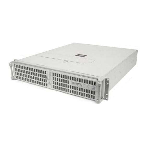
2RU 19” Rack-Mount Rugged Enterprise Server with X8DTN+ Motherboard Configuration /Two Quad/Dual-Core 5500 or Quad/Six-Core 5600 Xeon CPUs
Brand:
Themis
| Category:
Server
| Size: 3 MB
Table of Contents
Safety Precautions
4
Warnings and Cautions
4
Safety Instructions
6
Grounding Methods
7
Table of Contents
9
Preface
21
Table 1 RES-X2Xr3 20"-Deep Chassis Manual Matrix
22
Table 2 RES-X2Xr3S / RES-X1Xr3 17"-Deep Chassis Manual Matrix
23
Figure 2 Front View of a Standard Rear-I/O RES-22 Chassis (Doors Removed)
24
Table 3 Front I/O 16"-Deep Chassis Manual Matrix
24
Figure 3 Rear View of a Standard Rear-I/O RES-22 Chassis
25
Figure 4 Front View of a Front-I/O RES-32 Chassis
25
Figure 5 Rear View of a Front-I/O RES-32 Chassis
25
1 Overview and Specifications
29
Overview
29
Figure 1-1 RES-22XR3 Configuration 4 Configuration 4 (with Rack Mounts)
29
Table 1-1 RES-22XR3 Configuration 4 Motherboard Options
30
Figure 1-2 X8DTN+ Motherboard Block Diagram
31
Figure 1-3 External Features of the RES-22XR3 (Front and Rear)
32
Figure 1-4 Major Components of RES-22XR3 Configuration 4 (Open Top View)
33
System Leds and I/O Connectors
34
Figure 1-5 RES-22XR3 System Leds and I/O Connectors (X8DTN+ Motherboard)
34
Table 1-3 System Leds
35
Table 1-4 Power Supply LED Behavior
36
Table 1-5 Rear-Panel I/O Connectors
37
Chipset Overview
38
The 5500/5600 Series Processor and 5520 Chipset
38
Special Features
39
Recovery from AC Power Loss
39
PC Health Monitoring
39
Fan Status Monitor with Firmware Control
39
Environmental Temperature Control
39
System Resource Alert
40
ACPI Features
40
Slow Blinking LED for Suspend-State Indicator
40
Main Switch Override Mechanism
41
Wake-On-LAN (WOL)
41
Super I/O Controller
42
Specifications
43
General
43
Table 1-6 RES-22XR3 General Specifications
43
Electrical
44
System Power
44
Table 1-7 RES-22XR3 Configuration 4 Electrical Specifications
44
Output Voltage
45
Environmental
45
Electrostatic Discharge
45
Figure 1-6 RES-22XR3 with Front Sound Baffle Installed (Front View)
45
Noise
45
Shock
45
Figure 1-7 RES-22XR3 with Rear Sound Baffle Installed (Rear View)
46
Packaging and Shipping
47
Accessory Kit
47
Rack-Mount Slides (Optional)
48
Table 1-8 Approximate Weights of the RES Series
48
2 Installation and Operation
49
Installation Procedures
49
Remove Protective Top Cover
49
Figure 2-1 Remove the RES-22XR3 Protective Access Cover
50
Memory Modules
51
Table 2-1 RES-22XR3 Memory Capacity
51
Table 2-2 RES-22XR3 Memory Population
51
Figure 2-2 Remove RES-22XR3 Air-Flow Deflector (X8DTN+ Motherboard)
52
Installation
52
Figure 2-3 Memory Module Slot Locations (X8DTN+ Motherboard)
53
Figure 2-4 Memory Module Removal
54
PCI Cards
55
Figure 2-5 PCI Card Installation (X8DTN+ Motherboard)
55
Installing Cards
55
Lithium Battery
56
Figure 2-6 the RES-22XR3 Lithium Battery and Socket
56
Installing a Lithium Battery
56
Removing the Lithium Battery
56
Storage Drives
57
(Required for Storage Drive Access)
57
Figure 2-7 Opening the RES-22XR3 Front Doors
57
Opening the RES-22XR3 Front Doors
57
Figure 2-8 Unlocking the RES-22XR3 Storage Drives (Front Doors Removed)
58
Storage-Drive Removal
58
Figure 2-9 RES-22XR3 Storage Drive Removal
59
Storage-Drive Installation
59
Removable 80-MM Fan
60
Figure 2-10 the RES-22XR3 80-MM-Fans
60
Removing and Installing a 80-MM Fan
60
Figure 2-11 Fan Lid Lock
61
Power Supply
62
Figure 2-12 Locking Contact Area
62
Removing a Power Supply
62
Figure 2-13 the RES-22XR3 Power Supply Locking Mechanism
63
Installing a Power Supply
64
Rack Mounts
65
Mounting Brackets
65
Rack-Mount Slides (Optional)
65
Figure 2-14 Right Rack-Mount Bracket
65
Operation
66
Plugging in the AC Power Cords
66
Turning the System on
66
Figure 2-15 AC Power Socket and LED on the RES-22XR3 Rear
66
Figure 2-16 System Power Button and LED on the RES-22XR3 Front
66
Getting Started
67
Configuration
67
Linux Installation
67
Turning the System off
67
RES-22XR3 Installation Manual - Configuration 4 Version
68
3 BIOS Setup Utility
69
Introduction
69
Starting BIOS Setup Utility
69
How to Change the Configuration Data
70
Starting the Setup Utility
70
Main BIOS Setup
71
System Overview
71
Figure 3-1 Main BIOS Setup Screen
71
System Time/System Date
71
Processor
72
Super Micro X8DTN
72
System Memory
72
Advanced Setup Configurations
73
BOOT Features
73
Figure 3-2 BIOS Setup Utility Screen
73
Quick Boot
73
Quiet Boot
73
Addon ROM Display Mode
74
Bootup Num-Lock
74
Hit 'Del' Message Display
74
Interrupt 19 Capture
74
Wait for 'F1' if Error
74
Power Configuration
74
Power Button Function
74
Restore on AC Power Loss
75
Watch Dog Timer
75
Processor and Clock Options
75
Adjacent Cache Line Prefetch
75
C1E Support
75
Hardware Prefetcher
75
Ratio CMOS Setting
75
Active Processor Cores
76
Execute-Disable Bit Capability
76
Intel® Virtualization Technology
76
MPS and ACPI MADT Ordering
76
Simultaneous Multi-Threading
76
C-State Package Limit Setting
77
C1 Auto Demotion
77
C3 State
77
C6 State
77
Intel® C-STATE Tech
77
Intel® EIST Technology
77
Intel® Turbo Boost
77
C3 Auto Demotion
78
Clock Spread Spectrum
78
Advanced Chipset Control
78
QPI (Quick Path Interconnect) Links Speed
78
QPI Frequency
78
QPI L0S and L1
78
Cpu Bridge Configuration
78
Memory Frequency
78
Memory Mode
79
Demand Scrubbing
79
Patrol Scrubbing
79
Throttling - Closed Loop/Throttling - Closed Loop
79
Air Flow
80
Northbridge Configuration
80
Intel I/O at
80
DCA (Direct Cache Access)
81
DCA Prefetch Delay
81
Intel VT-D
81
Active State Power-Management
81
IOH PCIE Max Payload Size
81
Southbridge Configuration
81
USB Functions
82
Legacy USB Support
82
USB 2.0 Controller
82
USB 2.0 Controller Mode
82
BIOS EHCI Hand-Off
82
Intel PCI-X Hub Configuration
82
PCI Bus A0/B0 Frequency
82
I/O Port Decode
83
RAS (Row Address Strobe) Sticky Error Handling
83
VGA 16-Bit Decode
83
IDE/SATA Configuration
83
SATA#1 Configuration
83
SATA#2 Configuration
84
Primary IDE Master/Slave, Secondary IDE Master/Slave, Third IDE Master, and Fourth IDE Master
84
Pio Mode
84
DMA Mode
85
Table 3-1 PIO Mode Select Options
85
IDE Detect Timeout (Sec)
86
Pci/Pnp Configuration
86
Bit Data Transfer
86
Clear NVRAM
86
Plug & Play os
86
PCI Latency Timer
87
Boot Graphics Adapter Priority
87
Load Onboard LAN1 Option Rom/Load Onboard LAN2 Option ROM
87
Onboard LAN Option ROM Select
87
PCI IDE Busmaster
87
Slot1-Slot3 PCI-X Option Rom/Slot4-Slot6 PCI-E Option ROM
87
SR-IOV Supported
87
Floppy a
88
Onboard Floppy Controller
88
Remote Access
88
Remote Access Configuration
88
Serial Port Number
88
Serial Port1 Address/ Serial Port2 Address
88
Super IO Device Configuration
88
Flow Control
89
Hardware Health Configuration
89
Redirection after BIOS POST
89
Serial Port Mode
89
Sredir Memory Display Delay
89
Terminal Type
89
VT-UTF8 Combo Key Support
89
CPU Overheat Alarm
90
CPU Temperature 2/CPU Temperature 1/System Temperature
90
Fan Speed Readings
91
System Temperature
91
ACPI APIC Support
92
ACPI Aware O/S
92
ACPI Configuration
92
ACPI Version Features
92
Apic Acpi Sci Irq
92
Fan Speed Control Monitor
92
Voltage Readings
92
ACPI SLIT Table
93
Headless Mode
93
High Performance Event Timer
93
NUMA Support
93
TCG/TPM (Trusted Platform Module) Support
93
Trusted Computing
93
WHEA Support
93
Clear Event Log
94
Event Log Configuration
94
Mark All Events as Read
94
PCI-E Error Log
94
Tpm Owner Status
94
View Event Log
94
Security Settings
95
Change Supervisor Password
95
Figure 3-3 Security Settings
95
Supervisor Password
95
User Password
95
Boot Sector Virus Protection
96
Change User Password
96
Clear User Password
96
Password Check
96
Boot Configuration
97
Boot Device Priority
97
Figure 3-4 Boot Settings
97
Removable Drives
97
CD/DVD Drives
98
Network Drives
98
Retry Boot Devices
98
Storage Drives
98
USB Drives
98
Exit Options
99
Discard Changes and Exit
99
Figure 3-5 Exit Options
99
Save Changes and Exit
99
Discard Changes
100
Load Fail-Safe Defaults
100
Load Optimal Defaults
100
BIOS Recovery
101
Boot Sector Recovery from a USB Device
101
How to Recover the AMIBIOS Image
101
Boot Sector Recovery from a Serial Port ("Serial Flash")
102
Boot Sector Recovery from an IDE CD-ROM
102
How to Use Serial Flash for Boot Sector Recovery
102
Figure 3-6 AMI_FLSH Hyperterminal
104
Figure 3-7 ROM File Extraction
104
Figure 3-8 FLASH Recovery
105
Advertisement
Themis RES-22XR3 Installation Manual (162 pages)
2RU 19" Rack-Mount Rugged Enterprise Server with X8DTH-iF/X8DTH-6F Motherboard Configuration/Two Quad/Dual-Core 5500 or Quad/Six-Core 5600 Xeon CPUs
Brand:
Themis
| Category:
Server
| Size: 8 MB
Table of Contents
Version Revision History
5
Safety Instructions
7
Table of Contents
11
Figure 1 Rugged Enterprise Server Model RES-22XR3 (Doors Removed)
23
Preface
23
Table 1 RES-X2Xr3 20"-Deep Chassis Manual Matrix
24
Table 2 RES-X2Xr3S / RES-X1Xr3 17"-Deep Chassis Manual Matrix
25
Figure 2 Front View of a Standard Rear-I/O RES-22 Chassis (Doors Removed)
26
Table 3 Front I/O 16"-Deep Chassis Manual Matrix
26
Figure 3 Rear View of a Standard Rear-I/O RES-22 Chassis
27
Figure 4 Front View of a Front-I/O RES-22 Chassis
27
Figure 5 Rear View of a Front-I/O RES-22 Chassis
27
1 Overview and Specifications
31
Overview
31
Figure 1-2 X8DTH-If/X8Dth-6F Motherboard Block Diagram
33
Figure 1-3 External Features of the RES-22 (Front and Rear)
34
System Leds and I/O Connectors
35
Figure 1-4 RES-22 System Leds and I/O Connectors (Configuration 1)
35
Figure 1-5 Major Components of the RES-22 (Open Top View)
36
Table 1-3 Power Supply LED Behavior
37
Table 1-4 System Leds
38
Table 1-5 Rear-Panel I/O Connectors
39
Chipset Overview
40
The 5500/5600 Series Processor and 5520 Chipset
40
Special Features
41
Recovery from AC Power Loss
41
PC Health Monitoring
41
Fan Status Monitor with Firmware Control
41
Environmental Temperature Control
41
System Resource Alert
42
ACPI Features
42
Slow Blinking LED for Suspend-State Indicator
42
Main Switch Override Mechanism
43
Super I/O Controller
43
Winbond WPCM450 Controller
44
Specifications
45
General
45
Table 1-6 RES-22XR3 General Specifications
45
Electrical
46
Output Voltage
46
System Power
46
Table 1-7 RES-22XR3 Electrical Specifications
46
Environmental
47
Electrostatic Discharge
47
Figure 1-6 RES-22XR3 with Front Sound Baffle Installed (Front View)
47
Noise
47
Shock
47
Figure 1-7 RES-22XR3 with Rear Sound Baffle Installed (Rear View)
48
Packaging and Shipping
49
Accessory Kit
49
Rack-Mount Slides (Optional)
50
2 Installation and Operation
51
Installation Procedures
51
Remove Protective Top Cover
51
Figure 2-1 Remove the RES-22XR3 Protective Access Cover
52
Memory Modules
53
Figure 2-2 Remove Air-Flow Deflector Screws
54
Installation
54
Figure
55
Figure 2-3 Memory Module Slot Locations
55
PCI Cards
57
Installing Cards
57
Lithium Battery
58
Removing the Lithium Battery
58
Installing a Lithium Battery
59
SAS/SATA II Storage Drive
59
Opening the RES-22XR3 Front Doors
59
Storage-Drive Removal
60
Storage-Drive Installation
61
Removable 80-MM Fan
62
Figure 2-11 the RES-22XR3 80-MM-Fans
62
Removing and Installing a 80-MM Fan
63
Power Supply
64
Removing a Power Supply
64
Figure 2-14 the RES-22XR3 Power Supply Locking Mechanism
65
Installing a Power Supply
66
Rack Mounts
67
Mounting Brackets
67
Rack-Mount Slides (Optional)
67
Figure 2-15 Right Rack-Mount Bracket
67
Operation
68
Plugging in the AC Power Cords
68
Turning the System on
68
Figure 2-16 AC Power Socket and LED on the RES-22XR3 Rear
68
Figure 2-17 System Power Button and LED on the RES-22XR3 Front
68
Getting Started
69
Configuration
69
Linux Installation
69
Turning the System off
69
RES-22XR3 Installation Manual - Configuration 1 Version
70
3 BIOS Setup Utility
71
Introduction
71
Starting BIOS Setup Utility
71
How to Change the Configuration Data
72
Starting the Setup Utility
72
Main Setup
73
System Time/System Date
73
Figure 3-1 Main BIOS Setup Screen
73
Supermicro X8DTH
74
Processor
74
System Memory
74
Advanced Setup Configurations
75
Boot Features
75
Figure 3-2 Advanced Settings
75
Quick Boot
75
Quiet Boot
75
Addon ROM Display Mode
76
Bootup Num-Lock
76
Hit 'Del' Message Display
76
Interrupt 19 Capture
76
Power Button Function
76
Wait for 'F1' if Error
76
Watch Dog Function
76
Restore on AC Power Loss
77
Processor and Clock Options
77
Adjacent Cache Line Prefetch
77
Clock Spread Spectrum
77
CPU Ratio
77
Hardware Prefetcher
77
Execute-Disable Bit Capability
78
Intel® Virtualization Technology
78
Machine Checking Feature
78
MPS and ACPI MADT Ordering
78
Simultaneous Multi-Threading
78
Active Processor Cores
79
C-State Package Limit Setting
79
C1 Auto Demotion
79
C1E Support
79
Intel® C-STATE Tech
79
Intel® EIST Technology
79
Intel® Turbomode Technology
79
ACPI T State
80
C3 Auto Demotion
80
Advanced Chipset Control
80
QPI Links Speed
80
QPI Frequency
80
QPI L0S and L1
80
Memory Frequency
80
Memory Mode
81
Demand Scrubbing
81
Patrol Scrubbing
81
Channel Interleave
81
Bank Interleave
81
Throttling - Closed Loop
81
Intel I/OAT
82
DCA Technology
82
DCA Prefetch Delay
82
Intel VT-D
82
Active State Power Management
82
IOH PCI-E Max Payload Size
82
USB Functions
83
USB 2.0 Controller
83
Legacy USB Support
83
Port 64/60 Emulation
83
IDE/SATA Configuration
83
SATA#1 Configuration
83
Configure SATA#1 as
83
ICH RAID Code Base
84
ICH AHCI Code Base
84
SATA#2 Configuration
84
IDE Detect Timeout (Sec)
84
Primary IDE Master/Slave, Secondary IDE Master/Slave, Third IDE Master, and Fourth IDE Master
84
Table 3-1 PIO Mode Select Options
85
Pci/Pnp Configuration
87
Clear NVRAM
87
Plug & Play os
87
PCI Latency Timer
87
PCI Cache Size
87
PCI IDE Busmaster
87
SR-IOV Supported
87
PCI-E Slots 1~7 X8
88
Onboard LAN Options ROM Select
88
Boot Graphics Adapter Priority
88
Load Onboard LAN1 Option Rom/Load Onboard LAN2 Option ROM
88
Load Onboard SAS Option ROM
88
Serial Port1 Address/Serial Port2 Address
88
Super IO Device Configuration
88
Flow Control
89
Redirection after BIOS POST
89
Remote Access
89
Remote Access Configuration
89
Serial Port 2 Attribute
89
Serial Port Mode
89
Serial Port Number
89
CPU Overheat Alarm
90
Hardware Health Monitor
90
Sredir Memory Display Delay
90
Terminal Type
90
VT-UTF8 Combo Key Support
90
CPU 1 Temperature/Cpu 2 Temperature/System Temperature
91
ACPI APIC Support
93
ACPI Aware O/S
93
ACPI Configuration
93
ACPI Version Features
93
Apic Acpi Sci Irq
93
Headless Mode
93
Voltage Readings
93
High Performance Event Timer
94
NUMA Support
94
TCG/TPM (Trusted Platform Module) Support
94
Trusted Computing
94
WHEA Support
94
IPMI Configuration
95
IPMI Firmware Revision
95
Status of BMC
95
Channel Number
96
Clear BMC System Event Log
96
Set LAN Configuration
96
View BMC System Event Log
96
BMC Watch Dog Timer Action
97
Channel Number Status
97
IP Address Source
97
Event Log Configuration
98
Clear Event Log
98
Mark All Events as Read
98
Memory ECC Error Log
98
PCI Error Log
98
View Event Log
98
Security Settings
99
Supervisor Password
99
User Password
99
Change Supervisor Password
99
Figure 3-3 Security Settings
99
User Access Level
100
Change User Password
100
Clear User Password
100
Password Check
100
Boot Sector Virus Protection
100
Boot Configuration
101
Boot Device Priority
101
Storage Drives
101
Figure 3-4 Boot Settings
101
Removable Drives
102
CD/DVD Drives
102
Retry Boot Devices
102
Exit Options
103
Save Changes and Exit
103
Discard Changes and Exit
103
Figure 3-5 Exit Options
103
Discard Changes
104
Load Optimal Defaults
104
Load Fail-Safe Defaults
104
BIOS Recovery
105
How to Recover the AMIBIOS Image (Main BIOS Block)
105
Boot Sector Recovery from a USB Device
105
Boot Sector Recovery from an IDE CD-ROM
106
Boot Sector Recovery from a Serial Port ("Serial Flash")
106
Requirements
106
Figure 3-6 AMI_FLSH Hyperterminal
108
Figure 3-7 ROM File Extraction
108
Figure 3-8 Flash Recovery
109
Themis RES-22XR3 Installation Manual (142 pages)
2RU 19" x17" Rack-Mount Rugged Enterprise Server with X8SAX Motherboard Configuration/One Quad-Core 5500 or Quad/Six-Core 5600 Xeon CPU
Brand:
Themis
| Category:
Server
| Size: 2 MB
Table of Contents
Safety Precautions
4
Warnings and Cautions
4
Safety Instructions
6
Grounding Methods
7
Table of Contents
9
Preface
21
Figure 1 Rugged Enterprise Server Model RES-21XR3
21
Figure 1-1 RES-21XR3
22
Table 1 RES-X2Xr3-S / RES-X1Xr3 17" Chassis Manual Matrix (AC and DC Power Supplies)
22
Table 2 RES-X2Xr3 20" Chassis Manual Matrix (AC and DC Power Supplies)
23
Table 3 Front I/O 16" Chassis Manual Matrix (AC and DC Power Supplies)
24
1 Overview and Specifications
27
Overview
27
Table 1-1 RES-21XR3 for X8SAX Motherboard Options
28
Table 1-2 Major Features of the RES-21XR3
28
Figure 1-2 X8SAX Motherboard Block Diagram
29
Figure 1-3 External Features of RES-21XR3 for X8SAX (Front and Rear)
30
System Leds and I/O Connectors
31
Figure 1-4 Major Components of RES-21XR3 for X8SAX (Top View)
32
Figure 1-5 RES-21XR3 System Leds and I/O Connectors
33
Table 1-3 System Leds
34
Table 1-4 I/O Connectors
35
Chipset Overview
36
Features of the LGA 1366 Processor and the X58
36
PC Health Monitoring
36
Recovery from Main Power Loss
36
Onboard Voltage Monitoring
37
Fan Status Monitor with Firmware Control
37
CPU Overheat LED and Control
37
Power Configuration Settings
37
Slow Blinking LED for Suspend-State Indicator
37
BIOS Support for USB Keyboard
38
Main Switch Override Mechanism
38
Wake-On-LAN (WOL)
38
Super I/O
38
Specifications
40
General
40
Electrical
41
Output Voltage
41
System Power
41
Environmental
42
Electrostatic Discharge
42
Figure 1-6 RES-21XR3 with Front Sound Baffle Installed (Front View)
42
Noise
42
Shock
42
Figure 1-7 RES-21XR3 with Rear Sound Baffle Installed (Rear View)
43
Packaging and Shipping
44
Accessory Kit
44
Rack-Mount Slides (Optional)
45
2 Installation and Operation
47
Installation Procedures
47
Remove Protective Top Cover
47
Figure 2-1 Remove the RES-21XR3 Protective Access Cover
48
Memory Modules
49
Figure 2-2 Remove the Air-Flow Deflector Screws
51
Installation
51
Figure 2-3 Memory Module Slot Locations
52
PCI Cards
53
Figure 2-4 Memory Module Removal
53
Figure 2-5 RES-21XR3 for X8SAX PCI Card Installation
54
Figure 2-6 PCI Card Clamp
54
Installing Cards
54
Lithium Battery
55
Removing the Lithium Battery
55
Installing a Lithium Battery
56
SAS/SATA Storage Drive
56
Figure 2-7 the RES-21XR3 for X8SAX Lithium Battery and Socket
56
Figure 2-8 Opening the RES-21XR3 for X8SAX Front Bezel Doors
57
Figure 2-9 Unlocking the RES-21XR3 Storage Drives (Front Doors Open)
57
Opening the RES-21XR3 Front Doors
57
Storage-Drive Removal
58
Figure 2-10 RES-21XR3 Storage Drive Removal
59
Storage-Drive Installation
59
Hot-Swappable 80-MM Fan
60
Figure 2-11 the RES-21XR3 80-MM Fans
60
Removing and Installing a 80-MM Fan
60
Power Supply
61
Removing a Power Supply
61
Figure 2-12 the RES-21XR3 Power Supply Locking Mechanism
62
Installing a Power Supply
62
Rack Mounts
63
Mounting Brackets
63
Rack-Mount Slides (Optional)
63
Figure 2-13 Right Rack-Mount Bracket
63
Operation
64
Plugging in the AC Power Cords
64
Turning the System on
64
Figure 2-14 AC Power Socket and LED on the RES-21XR3 Rear
64
Getting Started
65
Configuration
65
Figure 2-15 System Power Button and LED on the RES-21XR3 Front
65
Linux Installation
65
Turning the System off
66
3 BIOS Setup Utility
67
Introduction
67
Starting BIOS Setup Utility
67
How to Change the Configuration Data
68
Starting the Setup Utility
68
Main BIOS Setup
69
System Time/System Date
69
Figure 3-1 Main BIOS Setup Screen
69
Ambios
70
Processor
70
System Memory
70
Advanced Setup Configurations
71
Boot Features
71
Figure 3-2 Advanced Settings
71
Quick Boot
71
Quiet Boot
71
Addon ROM Display Mode
72
Bootup Num-Lock
72
Hit 'Del' Message Display
72
Power Button Function
72
PS/2 Mouse Support
72
Restore on AC Power Loss
72
Wait for 'F1' if Error
72
Watch Dog Function
72
EUP Support
73
Interrupt 19 Capture
73
Processor and Clock Options
73
Clock Spread Spectrum
73
CPU Ratio
73
Adjacent Cache Line Prefetch (Available When Supported by the CPU)
74
Execute-Disable Bit Capability (Available When Supported by the os and the CPU)
74
Hardware Prefetcher (Available When Supported by the CPU)
74
Intel® Virtualization Technology (Available When Supported by the CPU)
74
MPS and ACPI MADT Ordering
74
Active Processor Cores
75
C-STATE Tech
75
C1E Support
75
Intel AES-NI (When Supported by the CPU)
75
Intel® EIST Technology
75
Intel® Turboboost Technology (Available When Intel® EIST Technology Is Enabled)
75
Simultaneous Multi-Threading (Available When Supported by the CPU)
75
C-State Package Limit Setting
76
C1 Auto Demotion
76
C3 Auto Demotion
76
ACPI T State
76
DCA Technology
76
DCA Prefetch Delay
76
Advanced Chipset Control
76
QPI & IMC Configuration
77
QPI Links Speed
77
QPI Frequency
77
QPI L0S and L1
77
Memory Frequency
77
Memory Mode
77
Demand Scrubbing
78
Patrol Scrubbing
78
Throttling - Closed Loop
78
HDA Controller
78
Intel VT-D
78
SR-IOV Support
79
Intel I/OAT
79
Active State Power Management
79
Route Port 80H Cycles to
79
Extend PCI Hole
79
USB Functions
79
USB 2.0 Controller
79
Legacy USB Support
80
IDE / Floppy Configuration
80
Floppy a
80
SATA#1 Configuration
80
SATA#2 Configuration
80
IDE Detect Timeout (Seconds)
80
Primary IDE Master/Slave, Secondary IDE Master/Slave, Third IDE Master, and Fourth IDE Master
81
Dma Mode
82
Pci/Pnp Configuration
83
Clear NVRAM
83
Plug & Play os
83
PCI Latency Timer
83
PCIX Slot Frequency
84
Boot Graphics Adapter Priority
84
Load Onboard LAN1/LAN2 Option ROM
84
PCI IDE Busmaster
84
PCI Slot 1-PCI Slot 6
84
Pcie I/O Performance
84
ROM Scan Ordering
84
Onboard Floppy Controller
85
Remote Access
85
Remote Access Configuration
85
Serial Port 1 Address / Serial Port 2 Address
85
Super IO Device Configuration
85
Hardware Health Configuration
86
CPU Overheat Alarm
87
CPU Temperature
87
Fan Speed Control Modes
89
Fan1-Fan 6 Reading
89
IOH Temperature
89
System Temperature
89
ACPI Aware O/S
90
ACPI Configuration
90
High Performance Event Timer
90
Suspend Mode
90
USB Device Wakeup from S3/S4
90
Voltage Reading
90
ACPI APIC Support
91
ACPI Version Features
91
AMI OEMB Table
91
Apic Acpi Sci Irq
91
Clear Event Log
91
Event Log Configuration
91
Headless Mode
91
Mark All Events as Read
91
View Event Log
91
Memory ECC Error Log
92
Pcie Error Log
92
Security Settings
92
Figure 3-3 Security Settings
92
Supervisor Password
92
Change Supervisor Password
93
Change User Password
93
User Access Level (When Supervisor Password Is Set)
93
User Password
93
Boot Sector Virus Protection
94
Boot Configuration
94
Boot Device Priority
94
Figure 3-4 Boot Settings
94
CD/DVD Drives
95
Hard Disk/Solid State Drives
95
Removable Drives
95
Exit Options
95
Figure 3-5 Exit Options
95
Discard Changes
96
Discard Changes and Exit
96
Load Fail-Safe Defaults
96
Load Optimal Defaults
96
Save Changes and Exit
96
BIOS Recovery
97
(Recommended Method)
97
Part 1-Boot Sector Recovery Process
97
Recovery Process from a USB Device
97
Figure 3-6 Flash Recovery
98
Part 2-BIOS Reprogramming (Re-Flashing)
98
Recovery from an IDE/SATA ATAPI Disc Drive
98
Advertisement
Themis RES-22XR3 Installation Manual (144 pages)
Configuration 3 2RU 19” Rack-Mount Rugged Enterprise Server with X8DT3/-F/-LN4F Motherboard Configuration / Two Quad-Core 5500 or Quad/Six-Core 5600 Xeon CPUs
Brand:
Themis
| Category:
Server
| Size: 1 MB
Table of Contents
Safety Precautions
4
Warnings and Cautions
4
Safety Instructions
6
Grounding Methods
7
Table of Contents
9
Preface
21
Figure 1 Rugged Enterprise Server RES-22XR3 (Doors Removed)
21
Table 1 RES-X2Xr3 20" Chassis Manual Matrix
22
Figure 2 Front View of a Standard Rear-I/O RES-22 Chassis (Doors Removed)
24
Table 3 Front I/O 16"-Deep Chassis Manual Matrix (AC and DC Power Supplies)
24
Figure 3 Rear View of a Standard Rear-I/O RES-22 Chassis
25
Figure 4 Front View of a Front-I/O RES-22 Chassis
25
Figure 5 Rear View of a Front-I/O RES-22 Chassis
25
RES-22XR3 Installation Manual - Configuration 3 Version
28
1 Overview and Specifications
29
Overview
29
Figure 1-1 RES-22XR3 Configuration 3 (with Rack Mounts)
29
Figure
30
Table 1-1 RES-22XR3 Configuration 3 Motherboard Options
30
Figure 1-2 X8DT3 Motherboard Block Diagram
31
Figure 1-3 External Features of the RES-22XR3 Configuration 3 (Front and Rear)
32
Figure 1-4 Major Components of RES-22XR3 Configuration 3 (Open Top View)
33
System Leds and I/O Connectors
34
Figure 1-5 RES-22XR3 Configuration 3 System Leds and I/O Connectors
34
Table 1-3 System Leds
35
Table 1-4 I/O Connectors (Rear Panel)
36
Chipset Overview
37
The 5500/5600 Series CPU and the 5520 Chipset
37
Special Features
38
Recovery from AC Power Loss
38
PC Health Monitoring
38
Fan Status Monitor with Firmware Control
38
Environmental Temperature Control
38
System Resource Alert
39
ACPI Features
39
Slow Blinking LED for Suspend-State Indicator
39
Main Switch Override Mechanism
40
Wake-On-LAN (WOL)
40
Power Supply
41
Super I/O Controller
42
Specifications
43
General
43
Table 1-5 RES-22XR3 General Specifications
43
Electrical
44
Output Voltage
44
System Power
44
Table 1-6 RES-22XR3 Electrical Specifications
44
Environmental
45
Electrostatic Discharge
45
Figure 1-6 RES-22XR3 with Front Sound Baffle Installed (Front View)
45
Noise
45
Shock
45
Packaging and Shipping
47
Accessory Kit
47
Rack-Mount Slides (Optional)
48
Table 1-7 Approximate Weights of the RES Series
48
2 Installation and Operation
49
Installation Procedures
49
Remove Protective Top Cover
49
Figure 2-1 Remove the RES-22XR3 Protective Access Cover
50
Memory Modules
51
Table 2-1 RES-22XR3 Memory Capacity
51
Installation
52
Figure 2-3 Memory Module Slot Locations (X8DT3 Motherboard)
53
PCI Cards
55
Installing Cards
55
Lithium Battery
56
Installing a Lithium Battery
56
Removing the Lithium Battery
56
SAS/SATA II Storage Drive
57
Opening the RES-22XR3 Front Door (Required for Storage Drive Access)
57
Figure
58
Storage-Drive Removal
58
Storage-Drive Installation
59
Removable 60-MM Fan
60
Figure 2-10 the RES-22XR3 Front and Rear 60-MM-Fans
60
Removing and Installing a 60-MM Fan
60
Power Supply
61
Removing a Power Supply
61
Installing a Power Supply
62
Rack Mounts
62
Mounting Brackets
62
Figure 2-12 Right Rack-Mount Bracket
62
Rack-Mount Slides (Optional)
63
Operation
64
Plugging in the AC Power Cords
64
Turning the System on
64
Figure 2-13 AC Power Socket and LED on the RES-22XR3 Rear
64
Figure 2-14 System Power Button and LED on the RES-22XR3 Front
64
Getting Started
65
Configuration
65
Linux Installation
65
Turning the System off
65
3 BIOS Setup Utility
67
Introduction
67
Starting BIOS Setup Utility
67
How to Change the Configuration Data
68
Starting the Setup Utility
68
Main Setup
69
System Overview
69
Figure 3-1 Main BIOS Setup Screen
69
System Time/System Date
69
Processor
70
Super Micro X8DT3
70
System Memory
70
Advanced Setup Configurations
71
BOOT Features
71
Addon ROM Display Mode
71
Bootup Num-Lock
71
Hit 'Del' Message Display
71
Quick Boot
71
Quiet Boot
71
Wait for 'F1' if Error
71
Interrupt 19 Capture
72
Power Configuration
72
Power Button Function
72
Restore on AC Power Loss
72
Watch Dog Timer
72
Processor and Clock Options
72
C1E Support
72
Adjacent Cache Line Prefetch (Available When Supported by the CPU)
73
Execute-Disable Bit Capability (Available When Supported by the os and the CPU)
73
Hardware Prefetcher (Available When Supported by the CPU)
73
Intel® Virtualization Technology (Available When Supported by the CPU)
73
Simultaneous Multi-Threading (Available When Supported by the CPU)
73
Active Processor Cores
74
Clock Spread Spectrum
74
Intel® C-STATE Tech
74
Intel® Speed_Step™ Technology
74
Advanced Chipset Control
74
QPI Links Speed
74
QPI Frequency
74
QPI L0S and L1
75
Memory Frequency
75
Memory Mode
75
Demand Scrubbing
75
Patrol Scrubbing
75
Throttling - Closed Loop/Throttling - Open Loop
75
Air Flow
76
Northbridge Configuration
77
Crystal Beach/Dma (Direct Memory Access)
77
Crystal Beach/Dca (Direct Cache Access)
77
NUMA Support
77
Intel VT-D
77
Southbridge Configuration
78
USB Functions
78
Legacy USB Support
78
USB 2.0 Controller
78
USB 2.0 Controller Mode
78
BIOS EHCI Hand-Off
78
HDA Controller
78
Reserved
78
IDE/SATA Configuration
79
SATA#1 Configuration
79
Configure SATA#1 as
79
SATA#2 Configuration
79
Primary IDE Master/Slave, Secondary IDE Master/Slave, Third IDE Master, and Fourth IDE Master
79
Block (Multi-Sector Transfer)
80
PIO Mode
80
DMA Mode
81
For Storage Drives
82
Bit Data Transfer
82
Hot Plug
82
IDE Detect Timeout (Sec)
82
Pci/Pnp Configuration
82
Clear NVRAM
82
Plug & Play os
82
PCI Latency Timer
82
PCI IDE Bus Master
83
Slot 1 Option Rom~Slot 6 Option ROM
83
Floppy A/Floppy B
83
Lan1 Pxe/Lan2 Pxe/Lan3 Pxe/Lan4 Pxe
83
Onboard Floppy Controller
83
Serial Port1 Address/ Serial Port2 Address
83
Super IO Device Configuration
83
Flow Control
84
Redirection after BIOS POST
84
Remote Access
84
Remote Access Configuration
84
Serial Port Mode
84
Watch Dog Timer
84
CPU Overheat Alarm
85
Sredir Memory Display Delay
85
System Health Monitor
85
Terminal Type
85
VT-UTF8 Combo Key Support
85
CPU Temperature/System Temperature
86
Fan1 ~ Fan 8 Reading
87
System Fan Monitor
87
System Temperature
87
Voltage Monitoring
87
ACPI APIC Support
88
ACPI Configuration
88
ACPI Version Features
88
Apic Acpi Sci Irq
88
Headless Mode
88
High Performance Event Timer
88
TCG/TPM (Trusted Platform Module) Support
88
Trusted Computing
88
IPMI Configuration
89
Status of BMC
89
View BMC System Event Log
89
Channel Number
90
Channel Number Status
90
Clear BMC System Event Log
90
IP Address Source
90
Set LAN Configuration
90
IP Address Configuration
91
Current IP Address in BMC
91
IP Address
91
Parameter Selector
91
MAC Address Configuration
91
Current MAC Address in BMC
91
MAC Address
91
Subnet Mask Configuration
92
Parameter Selector
92
Subnet Mask
92
VLAN Tagging
92
SEL PEF Configuration
92
PEF Configuration
92
BMC Watch Dog Timer Action
93
DMI Event Log
93
View Event Log
93
Clear Event Log
94
Mark All Events as Read
94
Security Settings
95
Supervisor Password
95
User Password
95
Change Supervisor Password
95
Figure 3-2 Security Settings
95
Change User Password
96
Clear User Password (Available Only if User Password Has Been Set)
96
Password Check
96
Boot Sector Virus Protection
96
Boot Configuration
97
Boot Device Priority
97
Storage Drives
97
Figure 3-3 Boot Settings
97
Removable Drives
98
CD/DVD Drives
98
Exit Options
98
Figure 3-4 Exit Options
98
Discard Changes
99
Discard Changes and Exit
99
Load Optimal Defaults
99
Load Fail-Safe Defaults
99
Save Changes and Exit
99
BIOS Recovery
100
Boot Sector Recovery from a USB Device
100
How to Recover the AMIBIOS Image (-The Main BIOS Block)
100
Boot Sector Recovery from a Serial Port ("Serial Flash")
101
Boot Sector Recovery from an IDE CD-ROM
101
Figure 3-5 AMI_FLSH Hyperterminal
103
Figure 3-6 ROM File Extraction
103
Figure 3-7 FLASH Recovery
104
Advertisement
Related Products
Themis RES-22DCX
Themis RES-21XR3
Themis RES-22XR3-S
Themis RES-22XR3/FIO
Themis RES-XR4-1U
Themis RES-12XR3
Themis RES-32DCX
Themis RES-31XR3
Themis RES-32XEL
Themis RES-32XR3-S
Themis Categories
Server
Barcode Reader
Laboratory Equipment
Motherboard
Video Card
More Themis Manuals
Login
Sign In
OR
Sign in with Facebook
Sign in with Google
Upload manual
Upload from disk
Upload from URL