Sign In
Upload
Manuals
Brands
Themis Manuals
Server
RES - 32XR3
Themis RES - 32XR3 Manuals
Manuals and User Guides for Themis RES - 32XR3. We have
2
Themis RES - 32XR3 manuals available for free PDF download: Installation Manual
Themis RES - 32XR3 Installation Manual (142 pages)
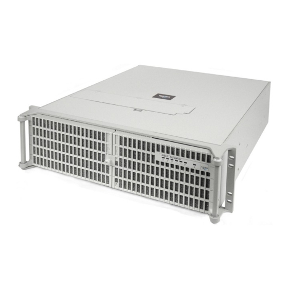
2RU 19" x17" Rack-Mount Rugged Enterprise Server with X8SAX Motherboard Configuration/One Quad-Core 5500 or Quad/Six-Core 5600 Xeon CPU
Brand:
Themis
| Category:
Server
| Size: 2.81 MB
Table of Contents
Safety Precautions
4
Warnings and Cautions
4
Safety Instructions
6
Grounding Methods
7
Table of Contents
9
Preface
21
Figure 1 Rugged Enterprise Server Model RES-21XR3
21
Figure 1-1 RES-21XR3
22
Table 1 RES-X2Xr3-S / RES-X1Xr3 17" Chassis Manual Matrix (AC and DC Power Supplies)
22
Table 2 RES-X2Xr3 20" Chassis Manual Matrix (AC and DC Power Supplies)
23
Table 3 Front I/O 16" Chassis Manual Matrix (AC and DC Power Supplies)
24
1 Overview and Specifications
27
Overview
27
Table 1-1 RES-21XR3 for X8SAX Motherboard Options
28
Table 1-2 Major Features of the RES-21XR3
28
Figure 1-2 X8SAX Motherboard Block Diagram
29
Figure 1-3 External Features of RES-21XR3 for X8SAX (Front and Rear)
30
System Leds and I/O Connectors
31
Figure 1-4 Major Components of RES-21XR3 for X8SAX (Top View)
32
Figure 1-5 RES-21XR3 System Leds and I/O Connectors
33
Table 1-3 System Leds
34
Table 1-4 I/O Connectors
35
Chipset Overview
36
Features of the LGA 1366 Processor and the X58
36
PC Health Monitoring
36
Recovery from Main Power Loss
36
Onboard Voltage Monitoring
37
Fan Status Monitor with Firmware Control
37
CPU Overheat LED and Control
37
Power Configuration Settings
37
Slow Blinking LED for Suspend-State Indicator
37
BIOS Support for USB Keyboard
38
Main Switch Override Mechanism
38
Wake-On-LAN (WOL)
38
Super I/O
38
Specifications
40
General
40
Electrical
41
Output Voltage
41
System Power
41
Environmental
42
Electrostatic Discharge
42
Figure 1-6 RES-21XR3 with Front Sound Baffle Installed (Front View)
42
Noise
42
Shock
42
Figure 1-7 RES-21XR3 with Rear Sound Baffle Installed (Rear View)
43
Packaging and Shipping
44
Accessory Kit
44
Rack-Mount Slides (Optional)
45
2 Installation and Operation
47
Installation Procedures
47
Remove Protective Top Cover
47
Figure 2-1 Remove the RES-21XR3 Protective Access Cover
48
Memory Modules
49
Figure 2-2 Remove the Air-Flow Deflector Screws
51
Installation
51
Figure 2-3 Memory Module Slot Locations
52
PCI Cards
53
Figure 2-4 Memory Module Removal
53
Figure 2-5 RES-21XR3 for X8SAX PCI Card Installation
54
Figure 2-6 PCI Card Clamp
54
Installing Cards
54
Lithium Battery
55
Removing the Lithium Battery
55
Installing a Lithium Battery
56
SAS/SATA Storage Drive
56
Figure 2-7 the RES-21XR3 for X8SAX Lithium Battery and Socket
56
Figure 2-8 Opening the RES-21XR3 for X8SAX Front Bezel Doors
57
Figure 2-9 Unlocking the RES-21XR3 Storage Drives (Front Doors Open)
57
Opening the RES-21XR3 Front Doors
57
Storage-Drive Removal
58
Figure 2-10 RES-21XR3 Storage Drive Removal
59
Storage-Drive Installation
59
Hot-Swappable 80-MM Fan
60
Figure 2-11 the RES-21XR3 80-MM Fans
60
Removing and Installing a 80-MM Fan
60
Power Supply
61
Removing a Power Supply
61
Figure 2-12 the RES-21XR3 Power Supply Locking Mechanism
62
Installing a Power Supply
62
Rack Mounts
63
Mounting Brackets
63
Rack-Mount Slides (Optional)
63
Figure 2-13 Right Rack-Mount Bracket
63
Operation
64
Plugging in the AC Power Cords
64
Turning the System on
64
Figure 2-14 AC Power Socket and LED on the RES-21XR3 Rear
64
Getting Started
65
Configuration
65
Figure 2-15 System Power Button and LED on the RES-21XR3 Front
65
Linux Installation
65
Turning the System off
66
3 BIOS Setup Utility
67
Introduction
67
Starting BIOS Setup Utility
67
How to Change the Configuration Data
68
Starting the Setup Utility
68
Main BIOS Setup
69
System Time/System Date
69
Figure 3-1 Main BIOS Setup Screen
69
Ambios
70
Processor
70
System Memory
70
Advanced Setup Configurations
71
Boot Features
71
Figure 3-2 Advanced Settings
71
Quick Boot
71
Quiet Boot
71
Addon ROM Display Mode
72
Bootup Num-Lock
72
Hit 'Del' Message Display
72
Power Button Function
72
PS/2 Mouse Support
72
Restore on AC Power Loss
72
Wait for 'F1' if Error
72
Watch Dog Function
72
EUP Support
73
Interrupt 19 Capture
73
Processor and Clock Options
73
Clock Spread Spectrum
73
CPU Ratio
73
Adjacent Cache Line Prefetch (Available When Supported by the CPU)
74
Execute-Disable Bit Capability (Available When Supported by the os and the CPU)
74
Hardware Prefetcher (Available When Supported by the CPU)
74
Intel® Virtualization Technology (Available When Supported by the CPU)
74
MPS and ACPI MADT Ordering
74
Active Processor Cores
75
C-STATE Tech
75
C1E Support
75
Intel AES-NI (When Supported by the CPU)
75
Intel® EIST Technology
75
Intel® Turboboost Technology (Available When Intel® EIST Technology Is Enabled)
75
Simultaneous Multi-Threading (Available When Supported by the CPU)
75
C-State Package Limit Setting
76
C1 Auto Demotion
76
C3 Auto Demotion
76
ACPI T State
76
DCA Technology
76
DCA Prefetch Delay
76
Advanced Chipset Control
76
QPI & IMC Configuration
77
QPI Links Speed
77
QPI Frequency
77
QPI L0S and L1
77
Memory Frequency
77
Memory Mode
77
Demand Scrubbing
78
Patrol Scrubbing
78
Throttling - Closed Loop
78
HDA Controller
78
Intel VT-D
78
SR-IOV Support
79
Intel I/OAT
79
Active State Power Management
79
Route Port 80H Cycles to
79
Extend PCI Hole
79
USB Functions
79
USB 2.0 Controller
79
Legacy USB Support
80
IDE / Floppy Configuration
80
Floppy a
80
SATA#1 Configuration
80
SATA#2 Configuration
80
IDE Detect Timeout (Seconds)
80
Primary IDE Master/Slave, Secondary IDE Master/Slave, Third IDE Master, and Fourth IDE Master
81
Dma Mode
82
Pci/Pnp Configuration
83
Clear NVRAM
83
Plug & Play os
83
PCI Latency Timer
83
PCIX Slot Frequency
84
Boot Graphics Adapter Priority
84
Load Onboard LAN1/LAN2 Option ROM
84
PCI IDE Busmaster
84
PCI Slot 1-PCI Slot 6
84
Pcie I/O Performance
84
ROM Scan Ordering
84
Onboard Floppy Controller
85
Remote Access
85
Remote Access Configuration
85
Serial Port 1 Address / Serial Port 2 Address
85
Super IO Device Configuration
85
Hardware Health Configuration
86
CPU Overheat Alarm
87
CPU Temperature
87
Fan Speed Control Modes
89
Fan1-Fan 6 Reading
89
IOH Temperature
89
System Temperature
89
ACPI Aware O/S
90
ACPI Configuration
90
High Performance Event Timer
90
Suspend Mode
90
USB Device Wakeup from S3/S4
90
Voltage Reading
90
ACPI APIC Support
91
ACPI Version Features
91
AMI OEMB Table
91
Apic Acpi Sci Irq
91
Clear Event Log
91
Event Log Configuration
91
Headless Mode
91
Mark All Events as Read
91
View Event Log
91
Memory ECC Error Log
92
Pcie Error Log
92
Security Settings
92
Figure 3-3 Security Settings
92
Supervisor Password
92
Change Supervisor Password
93
Change User Password
93
User Access Level (When Supervisor Password Is Set)
93
User Password
93
Boot Sector Virus Protection
94
Boot Configuration
94
Boot Device Priority
94
Figure 3-4 Boot Settings
94
CD/DVD Drives
95
Hard Disk/Solid State Drives
95
Removable Drives
95
Exit Options
95
Figure 3-5 Exit Options
95
Discard Changes
96
Discard Changes and Exit
96
Load Fail-Safe Defaults
96
Load Optimal Defaults
96
Save Changes and Exit
96
BIOS Recovery
97
(Recommended Method)
97
Part 1-Boot Sector Recovery Process
97
Recovery Process from a USB Device
97
Figure 3-6 Flash Recovery
98
Part 2-BIOS Reprogramming (Re-Flashing)
98
Recovery from an IDE/SATA ATAPI Disc Drive
98
Appendix A. Connector Pinouts
101
PS/2 Keyboard and Mouse
101
USB Ports
102
Gigabit Ethernet LAN Ports
102
Figure A-1 USB Connector Pinout
102
Figure A-2 Ethernet Connector, Type RJ45
102
Figure
102
High Definition Audio
103
Figure A-3 High Definition Audio Ports
103
S/Pdif_Out Connector
104
Figure A-4 S/Pdif_Out Connector
104
Table A-5 S/PDIF Bottom Component Pin Definition
105
Appendix B. Rack-Mount Slide Installation
107
Figure B-1 Screw Locations for Rack-Mount Slides
107
Appendix C. Red hat Enterprise Linux 5 Installation
111
Introduction
111
Installation
112
Step 1
112
Step 2
112
Figure C-1 Power on after Linux DVD Is Inserted into Drive
112
Figure C-2 Skip Key
112
Figure C-3 Welcome Screen
113
Figure C-4 Language Selection
113
C.2.3 Step 3
113
Step 6
114
Figure C-5 Selecting Layout Type
114
Figure C-6 Enter Installation Number
114
C.2.5 Step 5
114
Step 7
115
Figure C-7 Partitioning
115
C.2.7 Step 7
115
Step 8
116
Figure C-8 Reviewing Option
116
C.2.8 Step 8
116
Step 9
117
Figure C-9 Creating a Custom Layout
117
C.2.9 Step 9
117
Figure C-10 Setting up Boot Loader
118
C.2.10 Step 10
118
Figure C-11 Master Boot Record (MBR
119
Figure C-12 Network Devices List
120
Figure C-13 Edit Interface Pop-Up Screen
121
Figure C-14 Selecting Time Zone
122
Figure C-15 Setting up Root Account and Password
123
Figure C-16 Package Installation Default Screen
124
Figure C-17 Optional Packages
125
Step 19
126
Figure C-18 Option to Review or Continue
126
Figure C-19 Installation Begins
126
C.2.18 Step 18
126
Step 20
127
Step 21
128
Step 22
128
Appendix D. Optional Remote On/Off Switch
129
Remote On/Off Configuration
129
Remote Only Configuration
129
Remote On/Off Switch Module
129
Figure
129
Ordering the Remote On/Off Switch
130
Appendix E. Re-Packing Instructions
131
Re-Packaging for Shipment
131
Packing Components
131
Instructions for Re-Packing
132
Packaging Components
132
Figure
132
Index
135
Reader Comment Card
142
Advertisement
Themis RES - 32XR3 Installation Manual (146 pages)
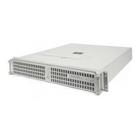
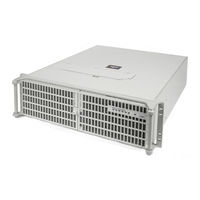
3RU 19” Rack-Mount Rugged Enterprise Server with X8DTi/X8DTi-F/X8DTi-LN4F Motherboard Configuration / Two Quad-Core 5500 or Quad/Six-Core 5600 Xeon CPUs
Brand:
Themis
| Category:
Server
| Size: 3.76 MB
Table of Contents
Safety Precautions
4
Warnings and Cautions
4
Safety Instructions
6
Grounding Methods
7
Table of Contents
9
Preface
21
Figure
24
1 Overview and Specifications
29
Overview
29
Table 1-1 RES-32XR3 Configuration 2 Motherboard Options
30
Figure 1-2 X8Dti Motherboard Block Diagram
31
Figure 1-3 External Features of RES-32XR3 Configuration 2 (Front and Rear)
32
Figure 1-4 Major Components of the RES-32XR3 Configuration 2 (Open Top View)
33
System Leds and I/O Connectors
34
Figure 1-5 RES-32XR3 Configuration 2 System Leds and I/O Connectors
34
Table 1-3 System Leds
35
Table 1-4 I/O Connectors
36
Chipset Overview
37
The 5500/5600 Series CPU and the 5520 Chipset
37
Special Features
38
Recovery from AC Power Loss
38
PC Health Monitoring
38
Fan Status Monitor with Firmware Control
38
Environmental Temperature Control
38
System Resource Alert
39
ACPI Features
39
Slow Blinking LED for Suspend-State Indicator
39
Main Switch Override Mechanism
40
Wake-On-LAN (WOL)
40
Power Supply
41
Super I/O Controller
42
Specifications
43
General
43
Table 1-5 RES-32XR3 Configuration 2 General Specifications
43
Electrical
44
Output Voltage
44
System Power
44
Table 1-6 RES-32XR3 Electrical Specifications
44
Environmental
45
Electrostatic Discharge
45
Figure 1-6 RES-32XR3 with Front Sound Baffle Installed (Front View)
45
Noise
45
Shock
45
Figure 1-7 RES-32XR3 with Rear Sound Baffle Installed (Rear View)
46
Packaging and Shipping
47
Accessory Kit
47
Rack-Mount Slides (Optional)
48
Table 1-7 Approximate Weights of the RES Series
48
2 Installation and Operation
49
Installation Procedures
49
Remove Protective Top Cover
49
Figure 2-1 Remove the RES-32XR3 Protective Access Cover
50
Memory Modules
51
Table 2-1 RES-32XR3 Configuration 2 Memory Capacity
51
Figure 2-2 Remove the Air-Flow Deflector Screws
52
Installation
52
Figure 2-3 Memory Module Slot Locations
53
PCI Cards
55
Installing Cards
55
Lithium Battery
56
Figure 2-7 the RES-32XR3 Configuration 2 Lithium Battery and Socket
56
Removing the Lithium Battery
56
Installing a Lithium Battery
57
SATA II Storage Drive
57
Figure 2-8 Opening the RES-32XR3 Front Bezel Doors
57
Opening the RES-32XR3 Front Doors
58
Storage-Drive Removal
58
Storage-Drive Installation
59
Removable 120-MM Fan
60
Figure 2-11 the Dual RES-32XR3 Configuration 2 120-MM Fans
60
Removing and Installing a 120-MM Fan
60
Index
60
Power Supply
61
Removing a Power Supply
61
Installing a Power Supply
62
Rack Mounts
63
Mounting Brackets
63
Rack-Mount Slides (Optional)
63
Figure 2-13 Right Rack-Mount Bracket
63
Operation
64
Plugging in the AC Power Cords
64
Turning the System on
64
Figure 2-14 AC Power Socket and LED on the RES-32XR3 Rear
64
Figure 2-15 System Power Button and LED on the RES-32XR3 Front
64
Getting Started
65
Configuration
65
Linux Installation
65
Turning the System off
65
3 BIOS Setup Utility
67
Introduction
67
Starting BIOS Setup Utility
67
How to Change the Configuration Data
68
Starting the Setup Utility
68
Main Setup
69
System Overview
69
Figure 3-1 Main BIOS Setup Screen
69
System Time/System Date
69
Processor
70
Supermicro X8DT3
70
System Memory
70
Advanced Setup Configurations
71
BOOT Features
71
Figure 3-2 Advanced Settings Screen
71
Quick Boot
71
Quiet Boot
71
Addon ROM Display Mode
72
Bootup Num-Lock
72
Hit 'Del' Message Display
72
Interrupt 19 Capture
72
Wait for 'F1' if Error
72
Power Configuration
72
Power Button Function
72
Restore on AC Power Loss
73
Watch Dog Timer
73
Processor and Clock Options
73
Adjacent Cache Line Prefetch (Available When Supported by the CPU)
73
C1E Support
73
Hardware Prefetcher (Available When Supported by the CPU)
73
Intel® Virtualization Technology (Available When Supported by the CPU)
73
Active Processor Cores
74
Execute-Disable Bit Capability (Available When Supported by the os and the CPU)
74
Intel® C-STATE Tech
74
Intel® Speed_Step™ Technology
74
Simultaneous Multi-Threading (Available When Supported by the CPU)
74
Clock Spread Spectrum
75
Advanced Chipset Control
75
QPI Links Speed
75
Memory Frequency
75
Memory Mode
75
QPI Frequency
75
QPI L0S and L1
75
Demand Scrubbing
76
Patrol Scrubbing
76
Throttling - Closed Loop / Throttling - Open Loop
76
Northbridge Configuration
77
Crystal Beach / DMA (Direct Memory Access)
77
Crystal Beach / DCA (Direct Cache Access)
78
NUMA Support
78
Intel VT-D
78
Southbridge Configuration
78
USB Functions
78
Legacy USB Support
78
USB 2.0 Controller
78
USB 2.0 Controller Mode
79
BIOS EHCI Hand-Off
79
HDA Controller
79
Reserved
79
IDE/SATA Configuration
79
SATA#1 Configuration
79
Configure SATA#1 as
79
SATA#2 Configuration
80
Primary IDE Master / Slave, Secondary IDE Master / Slave, Third IDE Master, and Fourth IDE Master
80
Block (Multi-Sector Transfer)
80
PIO Mode
81
DMA Mode
81
For Storage Drives
82
Bit Data Transfer
82
Hot Plug
82
IDE Detect Timeout (Sec)
82
Pci/Pnp Configuration
83
Clear NVRAM
83
Plug & Play os
83
PCI Latency Timer
83
PCI IDE Bus Master
83
Slot 1 Option Rom~Slot 6 Option ROM
83
Lan1 Pxe/Lan2 Pxe/Lan3 Pxe/Lan4 Pxe
83
Super IO Device Configuration
84
Onboard Floppy Controller
84
Floppy A/Floppy B
84
Serial Port1 Address/ Serial Port2 Address
84
Watch Dog Timer
84
Remote Access Configuration
84
Remote Access
84
Flow Control
85
Redirection after BIOS POST
85
Serial Port Mode
85
Sredir Memory Display Delay
85
Terminal Type
85
VT-UTF8 Combo Key Support
85
CPU Overheat Alarm
86
CPU Temperature/System Temperature
86
System Health Monitor
86
System Temperature
87
ACPI APIC Support
88
ACPI Configuration
88
ACPI Version Features
88
Apic Acpi Sci Irq
88
Fan1-Fan 8 Reading
88
System Fan Monitor
88
Voltage Monitoring
88
Headless Mode
89
High Performance Event Timer
89
IPMI Configuration
89
TCG/TPM (Trusted Platform Module) Support
89
Trusted Computing
89
Clear BMC System Event Log
90
Status of BMC
90
View BMC System Event Log
90
Channel Number
91
Channel Number Status
91
IP Address Configuration
91
IP Address Source
91
Parameter Selector
91
Set LAN Configuration
91
Current IP Address in BMC
92
IP Address
92
MAC Address Configuration
92
Current MAC Address in BMC
92
MAC Address
92
Parameter Selector
92
Subnet Mask Configuration
92
Subnet Mask
92
VLAN Tagging
93
SEL PEF Configuration
93
PEF Configuration
93
BMC Watch Dog Timer Action
94
DMI Event Log
94
Clear Event Log
94
Mark All Events as Read
94
View Event Log
94
Security Settings
95
Supervisor Password
95
User Password
95
Change Supervisor Password
95
Figure 3-3 Security Settings
95
User Access Level (Available When Supervisor Password Is Set as Above)
96
Change User Password
96
Clear User Password (Available Only if User Password Has Been Set)
96
Password Check
96
Boot Sector Virus Protection
96
Boot Configuration
97
Boot Device Priority
97
Storage Drives
97
Figure 3-4 Boot Settings
97
Removable Drives
98
CD/DVD Drives
98
Exit Options
98
Figure 3-5 Exit Options
98
Discard Changes
99
Discard Changes and Exit
99
Load Fail-Safe Defaults
99
Load Optimal Defaults
99
Save Changes and Exit
99
BIOS Recovery
100
Boot Sector Recovery from a USB Device
100
How to Recover the AMIBIOS Image (the Main BIOS Block)
100
Boot Sector Recovery from a Serial Port ("Serial Flash")
101
Boot Sector Recovery from an IDE CD-ROM
101
Figure 3-6 AMI_FLSH Hyperterminal
103
Figure 3-7 ROM File Extraction
103
Figure 3-8 FLASH Recovery
104
Appendix A. Connector Pinouts
105
PS/2 Keyboard and Mouse
105
Table A-1 PS/2 Keyboard/Mouse Pinouts
105
USB Ports
106
Serial Ports
106
SVGA Monitor Port
107
Table A-4 RES-32XR3 SVGA Connector-Pin Signals
107
Gigabit Ethernet LAN Ports
108
IPMI Dedicated LAN Port
108
Appendix B. Rack-Mount Slide Installation
109
Figure B-1 Screw Locations for Rack-Mount Slides
109
Figure B-2 RES-32XR3 Rack-Mount Slide Installation
111
Appendix C. Red hat Enterprise Linux 5 Installation
113
Introduction
113
Installation
113
Figure C-1 Power on after Linux DVD Is Inserted into Drive
114
Figure C-2 Skip Key
114
Figure C-3 Welcome Screen
115
Figure C-4 Language Selection
116
Figure C-5 Selecting Layout Type
117
Figure C-6 Enter Installation Number
118
Figure C-7 Partitioning
119
Figure C-8 Reviewing Option
120
Figure C-9 Creating a Custom Layout
121
Figure C-10 Setting up Boot Loader
122
Figure C-11 Master Boot Record (MBR
123
Figure C-12 Network Devices List
124
Figure C-13 Edit Interface Pop-Up Screen
125
Figure C-14 Selecting Time Zone
126
Figure C-15 Setting up Root Account and Password
127
Figure C-16 Package Installation Default Screen
128
Figure C-17 Optional Packages
129
Figure C-18 Option to Review or Continue
130
Appendix D. Optional Remote On/Off Switch
133
Remote On/Off Configuration
133
Remote On/Off Switch Module
133
Remote On-Only Configuration
134
Ordering the Remote On/Off Switch
134
Appendix E. Re-Packing Instructions
135
Re-Packaging for Shipment
135
Packing Components
135
Instructions for Re-Packing
136
Figure
136
Packaging Components
136
Advertisement
Related Products
Themis RES-32XR3/FIO
Themis RES-32XR3-S
Themis RES-32XEL
Themis RES-31XR3
Themis RES-32DCX
Themis RES-XR4-1U
Themis RES-22DCX
Themis RES-22XR3
Themis RES-12XR3
Themis RES-21XR3
Themis Categories
Server
Barcode Reader
Motherboard
Laboratory Equipment
Video Card
More Themis Manuals
Login
Sign In
OR
Sign in with Facebook
Sign in with Google
Upload manual
Upload from disk
Upload from URL