Table of Contents
Advertisement
Quick Links
Advertisement
Table of Contents

Related Manuals for Eagle Access Control Systems X9S


Summary of Contents for Eagle Access Control Systems X9S
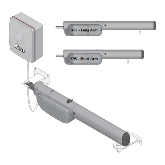
- Page 1 Swing Gate Operators ACCESS CONTROL SYSTEMS, INC. X9L - Long Arm Gate Capacity 16 ft - 800 lbs. IN C X9S - Short Arm Gate Capacity 10 ft - 700 lbs. Installation & Owners Manual AVI Slide Rev - C...
- Page 2 X9 Swing Rev - H...
- Page 3 Traveling Distance (Drive Screw) X9S: 13 3/4” X9L: 19 5/8” Max Gate Length X9S: 10 ft per Gate X9L: 16 ft Per Gate Max Gate Weight X9S: 700 lbs per Gate X9L: 800 lbs per Gate BY EAGLE ACCESS CONTROL SYSTEMS, INC.
- Page 4 SAFETY UL 325 Listings 1. Install the gate operator only when: a) The operator is appropriate for the construction of the gate and the usage class of the gate. b) All openings of a horizontal slide gate are guarded or screened from the bottom of the gate to a minimum of 6 feet (1.83 m) above the ground to prevent a 2-1/4 inch (57.2 mm) diameter sphere from passing through the openings anywhere in the gate, and in that portion of the adjacent fence that the gate covers in the open position.
-
Page 5: Ul 325 Model Classifications
UL 325 Model Classifications CLASS I CLASS I Residential Vehicular Gate Operator - A vehicular gate operator (opener or system) intended for use in a home of one to four single family dwellings, or a garage or parking area associated therewith. CLASS II CLASS II Commercial/General Access Vehicular Gate Operator - A... - Page 6 Swing Gate Recommendations Gates should have smooth bottom edges, with vertical bottom edged protrusions not exceeding 0.50 inches. Gate Closed Gate Closed With the hinge mounted on If distance is greater than 4 inches, the corner of the pilaster, the entrapment protection for this area entrapment area is recommended.
-
Page 7: Important Safety Information
General Safety Information CAUTION Be sure to read and follow all the Eagle Access Control Systems, Inc. and UL instructions before installing and operating any Eagle Access Control System, Inc. products. Eagle Access Control Systems, Inc. is not responsible for any improper installation procedures caused by failure to comply with local building codes. - Page 8 An experienced installer should perform the installation. Improper installation may result in property damage, severe injury or death. Read the entire manual before proceeding with the installation. Eagle Access Control Systems, Inc. is not responsible for researching and complying with local building codes. Be sure to check all local building codes before installation.
- Page 9 SAMPLE DUAL GATES INSTALLATION SETUPS These drawings are typical and is supplied as working model from which to choose the electronic components making up the dual gates installation. These drawings do not lay down any requirements regarding the installation of the gate operators. Please see the pages 2-5 for safety and general gate recommendations.
- Page 10 DISASSEMBLE OPERATOR Step 1 - Release Stroke Pin The stroke pin must be released before Door installation. 1. Unlock with Key and open door. 2. Flip orange handle forward. 3. Stroke pin can now be moved. NOTE: The stroke pin can REMAIN UNLOCKED by simply removing Released Position (Unlocked) the orange handle in the released...
- Page 11 MOUNT ARM X9L-Long Arm Min Stroke Max Stroke 18 3/4” 19 5/8” 38 1/2” X9S-Short Arm Stroke Pin 18 3/4” 13 3/4” 32 1/2” NOTE: Release the stroke pin before installation, see “Release Stroke Pin” on previous page. Option See pages 11 and 12 for dimensional layouts.
-
Page 12: Mount Control Box
MOUNT CONTROL BOX BY EAGLE ACCESS CONTROL SYSTEMS, INC. 4 5/8” 8 3/4” 7 1/2” Mount the control box as near as possible to Mounting Hole the actuator arm. Keep the box high enough above the ground to avoid landscape sprinklers and such. - Page 13 6 3/4 4 3/4 7 1/4 4 3/4 X9L-LONG Arm: MAX 16 ft per Gate 5 1/4 4 3/4 X9S-SHORT Arm: MAX 10 ft per Gate 6 3/4 6 3/4 4 3/4 5 1/2 4 3/4 4 3/4 The position of the brackets establishes the maximum opening angle and the length of the actuator's linear stroke.
- Page 14 OPEN OUTSIDE MOUNTING DIMENSIONS Only to be used with the X9L – Long Arm 4 3/4” 90°-105° Max Stroke = 38” Closed 7 1/2” Fabricated Bracket NOTE: Rear bracket 6” MUST be fabricated. The position of the brackets establishes the maximum opening angle and the length Bi-Parting Gates of the actuator's linear stroke.
-
Page 15: 120 Vac Input Power Connection
All operators MUST be properly grounded. Installing surge protection is recommended. Black White WARNING: Eagle Access Control Systems, Inc. is not Green responsible for researching and complying with local building codes. Be sure to check all local building codes POWER ENCODER before installation. -
Page 16: Photo Eye Installation
PHOTO EYE INSTALLATION / 4 ” Remove Hood Pull Out Pull Out Lift Up Max Sensing Range: 49 ft (15m) / Outdoors Remove cover / 4 ” with 4 screws 1 2 3 4 5 POWER ALIGN R.T: Resistive Min. Max. - Page 17 OPEN INSIDE - SINGLE OPERATOR & PHOTO EYE WIRING SW 1 = ON SEC TR 12 13 SW 2 = ON BSA FT1 J1 J2 PC PA PED STP P/P SW 3 = OFF (Photo Eye FT1) F16A SW 4 = ON SW 5 = OFF Prel.
- Page 18 OPEN OUTSIDE - SINGLE OPERATOR & PHOTO EYE WIRING Only to be used with the X9L – Long Arm SEC TR SW 1 = ON 12 13 SW 2 = ON BSA FT1 J1 J2 PC PA PED STP P/P SW 3 = OFF (Photo Eye FT1) F16A SW 4 = ON...
- Page 19 OPEN INSIDE - DUAL OPERATORS & PHOTO EYE WIRING SW 1 = ON SEC TR 12 13 SW 2 = ON BSA FT1 J1 J2 PC PA PED STP P/P SW 3 = OFF (Photo Eye FT1) F16A SW 4 = ON SW 5 = OFF Prel.
- Page 20 OPEN OUTSIDE - DUAL OPERATORS & PHOTO EYE WIRING Only to be used with the X9L – Long Arm SW 1 = ON SEC TR 12 13 SW 2 = ON BSA FT1 J1 J2 PC PA PED STP P/P SW 3 = OFF (Photo Eye FT1) F16A SW 4 = ON...
-
Page 21: Wiring Accessories
WIRING ACCESSORIES Stop Button Dry Contact SEC TR Used BSA FT1 J1 J2 PC PA PED STP P/P F16A 13-PIN Terminal 2 3 4 5 6 Prel. Rich DIP-Switch 7 OFF 2 3 4 5 6 7 C.Sg During opening/closing Rall. - Page 22 ADVANCED ACCESSORY CONNECTION Used with the 13-Pin Terminal - Entrapment Protection Photo Eye OPENING Direction Top View Side View Mount photo eye in position shown and run wire to control box in conduit. 10 11 10 11 MOTOR MOTOR MAG LOCK 24VDC 24 COM 1 LIMITS...
-
Page 23: Loop Detectors
LOOP DETECTORS Reverse, Phantom (Shadow) and Exit In-Ground Loop Installation Reversing and phantom loops are used to prevent the gate from closing on a vehicle while it is in the gates swinging path (CAUTION: phantom loop is ONLY active when gate is FULLY open, NOT during the closing cycle). -
Page 24: Dip-Switch Descriptions
DIP-SWITCH DESCRIPTIONS 12 13 13-PIN Terminal On Circuit Board BSA FT1 J1 J2 PC PA PED STP P/P 10 11 10 11 MOTOR MOTOR MAG LOCK 24VDC 24 COM 1 LIMITS 2 LIMITS Turn DIP-switch OFF for any CONNECTED device will INCLUDE them in Programming. Turning DIP-switch ON will EXCLUDE the corresponding terminal input. - Page 25 DIP-SWITCH DESCRIPTIONS s e t After changing DIP-switches, changes will take effect after: ON / OFF • Resetting the ECU (Momentarily short reset pins to RESET) • Shut power OFF and back ON again. • At the end of a complete gate cycle the new settings Prel.
-
Page 26: Programming & Adjustments
PROGRAMMING & ADJUSTMENTS Program Travel Distance and Pause Time to Close Gate(s) Limit switches and mechanical stops MUST be CORRECTLY positioned SINGLE Gate 12 13 BEFORE programming either SINGLE or BI-PARTING gates on next page. J1 J2 PC PA PED STP P/P J1 J2 DIP-Switch 9-Rall. - Page 27 BI-PARTING Gates Programming See “Programming Travel Distance and Pause Time to Close Gate(s)” statements about DIP-Swich settings etc. on previous page BEFORE programming Bi-Parting gates. ON / OFF Almost full Shut-off the power and Manually release the gate leaves and move them to an open position almost fully open position.
- Page 28 MODIFY PROGRAMMED PAUSE TIME TO CLOSE GATE This procedure allows you to modify the pause time set during previous programming procedure. This operation must be carried out with the gate CLOSED. 2 3 4 5 6 7 PROG Press the PROG button and hold it down until the Led LD1 lights up and remains lit. Press the PROG button again, LD1 will start to flash and start to memorize the pause time.
-
Page 29: Power Fail Operation
ADJUST REVERSE SENSOR Carry out the impact test and adjust the motor force by rotating the trimmer (TR1). If this is not sufficient, we advise you to install a rubber protective edge at the head of the gate so as to soften the impact. If you have adjusted the sensitivity setting and added a rubber profile to the head of the gate and you are still unable to satisfy the standards in force, you will need to add other safety devices such as a sensitive safety edge to the moving part of the gate. -
Page 30: Control Box Wiring Diagram
CONTROL BOX WIRING DIAGRAM 120V 50/60Hz SEC TR 12 13 Used BSA FT1 J1 J2 PC PA PED STP P/P F16A Prel. Rich 2 3 4 5 6 7 C.Sg Rall. PROG C.Ch 2 M. Fot.R STOP Pending Reset Used EL. - Page 31 X9 REPLACEMENT PARTS ILLUSTRATION Eagle Parts List on next page. 2(x2) 7(x2) 10(x2) Dual Operator Kit J-Box Terminal Block Moving Gate Can Cause Serious Injury or Death KEEP CLEAR! Gate may move at any time without prior warning. Do not let children operate the gate or play Extension in the gate area.
- Page 32 X9 REPLACEMENT PARTS LIST Item X9-Number Part Description X9002 X9 Operator Cover (Removable) X9004 X9 Cover Bolt (x2) X9006 X9 Key X9008 X9 Lock X9010 X9 Manual Release Handle X9012 X9 Limit Plate X9014 X9 Limit Switch (x2) X9016 X9 Stroke Screw Shaft X9018 X9 Stroke Pin Assembly X9020...
- Page 33 X9 Slide Rev - H...
- Page 34 ACCESS CONTROL SYSTEMS, INC. www.eagleoperators.com Toll Free: 1-800-708-8848 Phone: (818) 837-7900 Fax: (818) 837-7911 Eagle Access Control Systems, Inc. 12953 Foothill Blvd. Sylmar, Ca 91342 AVI Slide Rev - C Copyright © 2018 Eagle Access Control systems, Inc. All rights reserved.
Need help?
Do you have a question about the X9S and is the answer not in the manual?
Questions and answers