Table of Contents
Advertisement
Advertisement
Table of Contents

Related Manuals for MKS Baratron 127A


Summary of Contents for MKS Baratron 127A
- Page 1 110660-P1 Rev E, 6/97 Instruction Manual ® MKS Baratron Type 127A and Type 128A Absolute Pressure Transducers Six Shattuck Road Fax: (978) 975-0093 Andover, MA 01810-2449 E-mail: mks@mksinst.com (800) 227-8766 or (978) 975-2350 Web site: http://www.mksinst.com...
- Page 2 MKS Instruments, Inc. (MKS) warrants that the equipment described above (the “equipment”) manufactured by MKS shall be free from defects in materials and workmanship for a period of one year from date of shipment and will for a period of two years from the date of shipment, correctly perform all date-related operations, including...
- Page 3 110660-P1 Rev E, 6/97 MKS Baratron Type 127A and Type 128A Absolute Pressure Transducers...
- Page 4 All rights reserved. No part of this work may be reproduced or transmitted in any form or by any means, electronic or mechanical, including photocopying and recording, or by any information storage or retrieval system, except as may be expressly permitted in writing by MKS Instruments, Inc.
-
Page 5: Table Of Contents
Table of Contents Table of Contents Pressure Transducer Safety Information.................. 1 Symbols Used in This Instruction Manual..............1 Symbols Found on the Unit ..................2 Safety Procedures and Precautions ................3 Chapter One: General Information..................5 Introduction ....................... 5 How This Manual is Organized.................. 6 Customer Support ...................... - Page 6 Table of Contents Zero Check ....................21 How To Clean the Unit ..................21 Appendix A: Product Specifications..................23 Type 127 Performance Specifications.................23 Type 127 Physical Specifications ................24 Type 128 Performance Specifications.................25 Type 128 Physical Specifications ................26 Appendix B: Model Code Explanation...................27 Model Code .......................27 Index ............................29...
- Page 7 List of Figures and Tables List of Figures and Tables Figures Figure 1: Preferred Method To Connect an Overall Metal Braided Shielded Cable ....12 Figure 2: Alternate Method To Connect an Overall Metal Braided Shielded Cable ....12 Figure 3: Dimensions of a Low Range Type 127/128 Transducer .......... 14 Figure 4: Dimensions of a High Range Type 127/128 Transducer .........
- Page 8 List of Figures and Tables...
-
Page 9: Pressure Transducer Safety Information
Pressure Transducer Safety Information Pressure Transducer Safety Information Symbols Used in This Instruction Manual Definitions of WARNING, CAUTION, and NOTE messages used throughout the manual. Warning The WARNING sign denotes a hazard. It calls attention to a procedure, practice, condition, or the like, which, if not correctly performed or adhered to, could result in injury to personnel. -
Page 10: Symbols Found On The Unit
Pressure Transducer Safety Information Symbols Found on the Unit The following table describes symbols that may be found on the unit. Definition of Symbols Found on the Unit Protective earth (ground) Off (Supply) Earth (ground) On (Supply) IEC 417, No.5019 IEC 417, No.5017 IEC 417, No.5008 IEC 417, No.5007... -
Page 11: Safety Procedures And Precautions
DO NOT SUBSTITUTE PARTS OR MODIFY INSTRUMENT Do not install substitute parts or perform any unauthorized modification to the instrument. Return the instrument to an MKS Calibration and Service Center for service and repair to ensure that all safety features are maintained. - Page 12 Pressure Transducer Safety Information CHECK FOR LEAK-TIGHT FITTINGS Before proceeding to instrument setup, carefully check all plumbing connections to the instrument to ensure leak-tight installation. OPERATE AT SAFE INLET PRESSURES This unit should never be operated at pressures higher than the rated maximum pressure (refer to the product specifications for the maximum allowable pressure).
-
Page 13: Chapter One: General Information
The overpressure limit is 35 psia, maximum, for all ranges except 0.1 Torr range which is 20 psia, maximum. (However, MKS recommends that you install an isolation valve to achieve the best zero stability.) -
Page 14: How This Manual Is Organized
How This Manual is Organized Chapter One: General Information How This Manual is Organized This manual is designed to provide instructions on how to set up, install, and operate a Type 127/128 unit. Before installing your Type 127/128 unit in a system and/or operating it, carefully read and familiarize yourself with all precautionary notes in the Safety Messages and Procedures section at the front of this manual. -
Page 15: Customer Support
Calibration and Service Center before shipping. The ERA Number expedites handling and ensures proper servicing of your instrument. Please refer to the inside of the back cover of this manual for a list of MKS Calibration and Service Centers. Warning All returns to MKS Instruments must be free of harmful, corrosive, radioactive, or toxic materials. - Page 16 Customer Support Chapter One: General Information This page intentionally left blank.
-
Page 17: Chapter Two: Installation
If you find any damage, notify your carrier and MKS immediately. If it is necessary to return the unit to MKS, obtain an ERA Number (Equipment Return Authorization Number) from the MKS Service Center before shipping. -
Page 18: Interface Cables
January 1, 1997, some products shipped to the European Community must also comply with the Product Safety Directive 92/59/EEC and Low Voltage Directive 73/23/EEC, which cover general safety practices for design and workmanship. MKS products that meet these requirements are identified by application of the CE Mark. -
Page 19: Generic Shielded Cable Description
Chapter Two: Installation Interface Cables Generic Shielded Cable Description Should you choose to manufacture your own cables, follow the guidelines listed below: 1. The cable must have an overall metal braided shield, covering all wires. Neither aluminum foil nor spiral shielding will be as effective; using either may nullify regulatory compliance. 2. -
Page 20: Example 1: Preferred Method To Connect Cable
Interface Cables Chapter Two: Installation Example 1: Preferred Method To Connect Cable (shown on a transducer) Metal Cable Clamp Screw Transducer Split Lock Washer Overall Insulation External Tooth Lock Washer (if present) Bare Metal Cable Clamp Transducer Housing Making Firm Contact To Braid Braid Here Is Desirable Optional Plastic or Metal Cable (but not usually necessary) -
Page 21: Product Location And Requirements
Chapter Two: Installation Product Location and Requirements Product Location and Requirements Operating Environmental Requirements • Ambient Operating Temperature: 15° C to 40° C (59° F to 104° F) Setup The 127/128 transducer is designed to be mounted in any orientation and should be zeroed in that position. -
Page 22: Dimensions
Setup Chapter Two: Installation Dimensions Note All dimensions are listed in inches with millimeters referenced in parentheses. 3.00 (76.2) 0.500 (12.7) diameter diameter 0.19 (4.7) 3.74 (95.0) 1.31 (33.3) Figure 3: Dimensions of a Low Range Type 127/128 Transducer Cajon 8-VCR (or equivalent) for high range units 3.00 (76.2) diameter... -
Page 23: Electrical Information
Chapter Two: Installation Electrical Information Zero Pot BARATRON Type 12X Zero Interface Connector Pressure Transducer +15VDCXXXmA Figure 5: Top View of a Type 127/128 Transducer Electrical Information The Type 127 transducer requires an external power source capable of supplying ±15 VDC, ±5%, at 250 mA minimum. -
Page 24: Connector
Electrical Information Chapter Two: Installation Connector The 127/128 transducer has one 15-pin Type “D” connector located on the top of the unit. Refer to Figure 5, page 15, for the location of the connector. Pinout of the Interface Connector Pin Number Assignment No Connection Pressure Output... -
Page 25: Chapter Three: Overview
Chapter Three: Overview Circuit Description Chapter Three: Overview Circuit Description The variable capacitance sensor consists of rigidly attached capacitive electrodes located on the back or reference side of a metal diaphragm. The reference side is permanently evacuated and sealed thus making the pressure measurement totally independent of the gas type or composition. When pressure is applied to the diaphragm, its deflection produces a change in the distance between the electrodes and diaphragm and a resultant capacitance change. -
Page 26: Labels
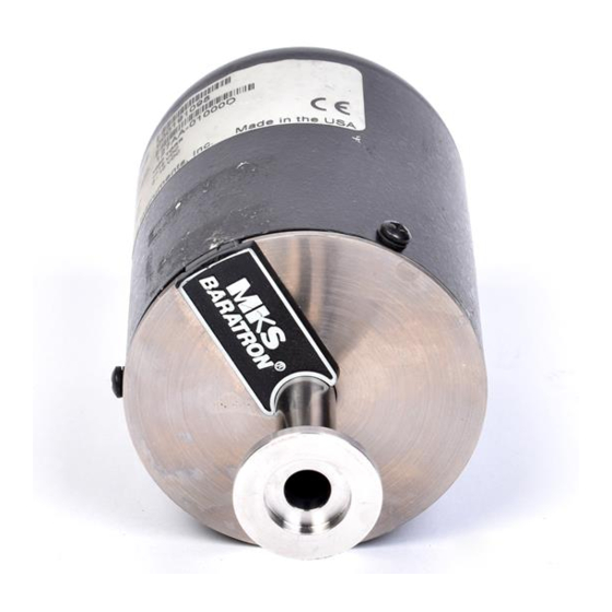
CE symbol indicating that the 127/128 transducer meets the requirements of the European Community’s EMC Directive 89/336/EEC. Serial #: 000103408 Model #: 127AA-0001B Range: .1 TORR Input: +/-15 VDC Output: 0 - 10 VDC MKS Instruments, Inc. Made in the USA Figure 7: Serial Number Label... -
Page 27: Chapter Four: Operation
2. Adjust the zero by turning the Zero potentiometer, located on the top of the unit. Refer to Figure 5, page 15, for the location of the Zero pot. The zero adjustment may also be made at the front panel of an MKS supplied readout/power supply unit, if used. -
Page 28: Table 4: Lowest Suggested Pressure Reading
How To Zero the Type 127/128 Transducer Chapter Four: Operation Lowest Suggested Pressure Reading Full Scale Range Lowest Pressure Reading 0.1 Torr 5 x 10 Torr 1 Torr 5 x 10 Torr 2 Torr 1 x 10 Torr 10 Torr 5 x 10 Torr 100 Torr... -
Page 29: Chapter Five: Maintenance
Chapter Five: Maintenance General Information Chapter Five: Maintenance General Information Periodically check for wear on the cables and inspect the unit for visible signs of damage. Caution Do not attempt to repair the transducer signal conditioner electronics since replacement or movement of PC board components may require complete recalibration of the unit. - Page 30 General Information Chapter Five: Maintenance This page intentionally left blank.
-
Page 31: Appendix A: Product Specifications
Appendix A: Product Specifications Type 127 Performance Specifications Appendix A: Product Specifications Type 127 Performance Specifications Accuracy 0.25% of Reading ± temperature coefficient Torr± 0.15% of Reading ± temperature coefficient 1 to 1000 Torr± 0.12% of Reading ± temperature coefficient >1000 to 25K Torr±... -
Page 32: Type 127 Physical Specifications
Type 127 Physical Specifications Appendix A: Product Specifications Type 127 Physical Specifications Fittings ½ inch diameter tubulation, Cajon 8-VCR, Cajon 8-VCO, NW-16-KF (not available for 10K through 25K Torr units), Mini-CF, rotatable Full Scale Pressure Range (in Torr) 0.1, 1, 2, 10, 100, 1000, 5K, 10K, 15K, 20K, Input Power ±15 VDC ±5%, 250 mA at startup... -
Page 33: Type 128 Performance Specifications
Appendix A: Product Specifications Type 128 Performance Specifications Type 128 Performance Specifications Accuracy 0.5% of Reading ± temperature coefficient Torr± 0.25% of Reading ± temperature coefficient 1 to 25K Torr± CE Compliance EMC Directive 89/336/EEC Electromagnetic Compatibility Resolution 0.01% of Full Scale Response Time <16 milliseconds Temperature Coefficient... -
Page 34: Type 128 Physical Specifications
Type 128 Physical Specifications Appendix A: Product Specifications Type 128 Physical Specifications Fittings ½ inch diameter tubulation, Cajon 8-VCR, Cajon 8-VCO, NW-16-KF (not available for 10K through 25K Torr units), Mini-CF, rotatable Full Scale Pressure Range (in Torr) 0.1, 1, 2, 10, 100, 1000 Input Power ±15 VDC ±5%, 500 mA at startup... -
Page 35: Appendix B: Model Code Explanation
Appendix B: Model Code Explanation Model Code Appendix B: Model Code Explanation Model Code The options of your transducer are identified in the model code when you order the unit. The model code is identified as follows: 12XAYYYYYZ where: 12XA XXXXX Z Type Number Full Scale Range... - Page 36 Model Code Appendix B: Model Code Explanation Full Scale Range (XXXXX) The full scale range is indicated by a five digit code. Full Scale Range Ordering Code 000.1 00001 00002 00010 00100 1,000 01000 5,000 05000 10,000 10000 15,000 15000 20,000 20000 25,000...
-
Page 37: Index
Index Index Accuracy, 23, 25 Maintenance, 21 Manual organization, 6 Model code, 27 CE compliance, 5, 10, 18, 23, 25 Mounting, 13 Circuit, 17 Cleaning, 21 Controllers, 10 Overpressure, 5 Customer support, 7 Pressure Dimensions, 14 control, 20 reading, 20 zero, 19 Electrical, 15–16 Range, 28... - Page 38 Index Vibration, 13 Wetted material, 5, 24, 26 Zero, 13, 19, 21...
Need help?
Do you have a question about the Baratron 127A and is the answer not in the manual?
Questions and answers