Table of Contents
Advertisement
Quick Links
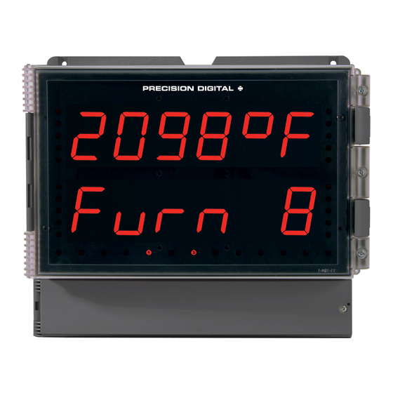
• Large 1.80" Digits
• Dual-Line 6-Digit Display
• Readable from up to 100 Feet (30 Meters) Away
• Superluminous Sunlight Readable Display
• NEMA 4X, IP65 Rated Field Mountable Enclosure
• Operating Temperature Range of -20 to 65°C (-4 to 150°F)
• J, K, T, E, R, S, B, N, C Thermocouples
• 100 or 1000 Ω Platinum, 10 Ω Copper, 120 Ω Nickel RTDs
• 1° or 0.1° Resolution
• Averages up to 10 RTD Sensors
• Automatic Cold Junction Compensation
• Input Power Options Include 85-265 VAC or 12-24 VDC
• Programmable Display & Function Keys
• 2 or 4 Relays + Isolated 4-20 mA Output Options
• Onboard USB & RS-485 Serial Communication Options
• Modbus
• Program the Meter from a PC with onboard USB and MeterView Pro
Precision Digital Corporation
1.800.561.8187
Helios Large Display Temperature Meter
Instruction Manual
®
RTU Communication Protocol Standard
www.
USB Install
Temperature
information@itm.com
.com
PD2-7000
Advertisement
Table of Contents

Related Manuals for PRECISION DIGITAL Helios PD2-7000 Series


Summary of Contents for PRECISION DIGITAL Helios PD2-7000 Series
- Page 1 • 2 or 4 Relays + Isolated 4-20 mA Output Options • Onboard USB & RS-485 Serial Communication Options • Modbus ® RTU Communication Protocol Standard • Program the Meter from a PC with onboard USB and MeterView Pro Precision Digital Corporation 1.800.561.8187 information@itm.com www. .com...
-
Page 2: Limited Warranty
Precision Digital Corporation warrants this product against defects in material or workmanship for the specified period under “Specifications” from the date of shipment from the factory. Precision Digital’s liability under this limited warranty shall not exceed the purchase value, repair, or replacement of the defective unit. -
Page 3: Table Of Contents
PD2-7000 Helios Large Display Temperature Meter Instruction Manual Table of Contents Table of Contents ............ 3 Programming Time Delay ........31 Relay Action for Loss of 4-20 mA Input (Loop Break) Table of Figures ............4 ................31 Introduction.............. 4 Relay and Alarm Operation Diagrams ....... -
Page 4: Table Of Figures
Helios Large Display Temperature Meter Instruction Manual PD2-7000 Table of Figures Figure 1. Meter Mounting Holes ......10 Figure 14. AC and DC Loads Protection ....15 Figure 2. Meter Dimensions - Side View ....10 Figure 15. Low Voltage DC Loads Protection ..15 Figure 3. -
Page 5: Ordering Information
PD2-7000 Helios Large Display Temperature Meter Instruction Manual Ordering Information Standard Models 85-265 VAC Model 12-24 VDC Model Options Installed PD2-7000-6H0 PD2-7000-7H0 No Options PD2-7000-6H7 PD2-7000-7H7 4 relays & 4-20 mA output Accessories Model Description PDA6260 Pipe Mounting Kit PDA7485-I RS-232 to RS-422/485 isolated converter PDA7485-N RS-232 to RS-422/485 non-isolated converter... -
Page 6: Temperature Input
Helios Large Display Temperature Meter Instruction Manual PD2-7000 Environmental Operating temperature range: -40 to Sensor Break Open TC or RTD sensor indicated by 150°F (-40 to 65°C) Detection display flashing oPEn, Storage temperature range: -40 to relays can be programmed to go 185°F (-40 to 85°C) “On”, “Off”, or to “Ignore”... -
Page 7: Isolated 4-20 Ma Transmitter Output
PD2-7000 Helios Large Display Temperature Meter Instruction Manual Relay Reset User selectable via front panel buttons Output Loop Power supply Minimum Maximum or digital inputs Resistance 24 VDC 10 700 Automatic reset only (non- 35 VDC 100 1200 ... -
Page 8: Compliance Information
Helios Large Display Temperature Meter Instruction Manual PD2-7000 Compliance Information Safety UL & C-UL Listed USA & Canada UL 508 Industrial Control Equipment (United States), C22.2 No. 142 (Canadian National Standard) UL File Number E160849 Front Panel UL Type 4X, NEMA 4X, IP65 Low Voltage Directive EN 61010-1:2010 Safety requirements for measurement, control, and laboratory use... -
Page 9: Safety Information
PD2-7000 Helios Large Display Temperature Meter Instruction Manual Safety Information Caution: Read complete instructions Warning: Risk of electric shock or prior to installation and operation of the personal injury. meter. Hazardous voltages exist within enclosure. Installation and service should be performed only by trained service personnel. -
Page 10: Wall Mounting Instructions
Helios Large Display Temperature Meter Instruction Manual PD2-7000 Wall Mounting Instructions The meter can be mounted to any wall using the four provided mounting holes. Note that the bottom mounting holes are located underneath the front door panel. To mount the meter to a wall, follow these instructions. -
Page 11: Pipe Mounting Instructions
PD2-7000 Helios Large Display Temperature Meter Instruction Manual Pipe Mounting Instructions The meter can also be mounted to a pipe using the optional pipe mounting kit (PDA6260). This kit includes two mounting plates, two U-bolts, and the necessary nuts and bolts. To mount the meter to a pipe using the pipe mounting kit accessory, follow these instructions. -
Page 12: Connections
The connectors’ label, affixed to the inside of the lower door panel, shows the location of all connectors available with requested configuration. Do not connect any equipment other than Precision Digital’s expansion modules, cables, or meters to the RJ45 M-LINK connector. -
Page 13: Signal Connections
PD2-7000 Helios Large Display Temperature Meter Instruction Manual Signal Connections Signal connections are made to a three-terminal connector labeled SIGNAL on Figure 6. Thermocouple and RTD Connections The following figures show examples for thermocouple and RTD connections. The TYPE selector switch must be set to the proper position for the meter to accept the selected RTD or TC input. -
Page 14: Connections For Averaging Rtd Sensors
Helios Large Display Temperature Meter Instruction Manual PD2-7000 Connections for Averaging RTD Sensors To obtain the average temperature from 2 to 10 RTD sensors, connect all the sensors in parallel and select the number of sensors in the RTD Total (rtdtot) menu. See the Advanced Features Menu on page 40. -
Page 15: Switching Inductive Loads
Figure 15. Low Voltage DC Loads Protection RC Networks Available from Precision Digital RC networks are available from Precision Digital and should be applied to each relay contact switching an inductive load. Part number: PDX6901. Note: Relays are de-rated to 1/14th HP (50 watts) with an inductive load. -
Page 16: Rs485 Output Connections
Helios Large Display Temperature Meter Instruction Manual PD2-7000 RS485 Output Connections An RS-485 connector is provided for the use of advanced Modbus ® serial communications. This connector converts the serial output of the meter to balanced, full or half-duplex RS-485 signals. It has a removable screw terminal connector for the RS-485 terminals which includes Transmit Data (DO) and (/DO), Receive Data (DI) and (/DI), and Signal Ground. -
Page 17: Figure 17. Rs-485 Two-Wire Multi-Drop Wiring
PD2-7000 Helios Large Display Temperature Meter Instruction Manual Figure 17. RS-485 Two-Wire Multi-Drop Wiring Notes: 1. Termination resistors are optional and values depend on the cable length and characteristic impedance. Consult the cable manufacturer for recommendations. 2. Refer to RS-232 to RS-485 Converter documentation for further details. 3. -
Page 18: Digital I/O Connections
Helios Large Display Temperature Meter Instruction Manual PD2-7000 Digital I/O Connections Digital inputs and outputs are provided in order to expand the functionality of the meter. Digital inputs are made via a push button or switch connection to the appropriate digital input connector block and the +5 VDC block. -
Page 19: 4-20 Ma Output Connections
PD2-7000 Helios Large Display Temperature Meter Instruction Manual 4-20 mA Output Connections Connections for the 4-20 mA transmitter output are made to the connector terminals labeled MA OUT. The 4-20 mA output may be powered internally or from an external power supply. Figure 22. -
Page 20: Setup And Programming
Helios Large Display Temperature Meter Instruction Manual PD2-7000 Setup and Programming The meter is factory calibrated prior to shipment to read temperature in degrees Fahrenheit. The calibration equipment is certified to NIST standards. Overview There are two switches, located to the right of the signal input connector, used to set the input selection for thermocouple or RTD and for 100-ohm platinum or 10-ohm copper. -
Page 21: Programming Buttons And Status Led Indicators
PD2-7000 Helios Large Display Temperature Meter Instruction Manual Programming Buttons and Status LED Indicators The meter can be programmed using the buttons located behind the front door panel. Use the Menu button to enter or exit Programming Mode, the Up Arrow button to cycle through menu options, and the Enter button to select the menu item or option you want. -
Page 22: Meterview ® Pro Software
Helios Large Display Temperature Meter Instruction Manual PD2-7000 MeterView ® Pro Software The meter can also be programmed using the PC-based MeterView Pro software included with the meter. This software is can be installed on any Microsoft® Windows® (2000/XP/Vista/7/8/10) computer by connecting the meter’s onboard USB. -
Page 23: Display Functions & Messages
PD2-7000 Helios Large Display Temperature Meter Instruction Manual Display Functions & Messages The meter displays various functions and messages during setup, programming, and operation. The following table shows the main menu functions and messages in the order they appear in the menu. Display Parameter Action/Setting Description... - Page 24 Helios Large Display Temperature Meter Instruction Manual PD2-7000 Display Parameter Action/Setting Description Ignore Ignore loop break condition (Processed as a low signal condition) ignore Relay goes to alarm condition when loop break is detected Relay goes to non-alarm condition when loop break is detected Enter the Analog output scaling menu Analog output Aout...
-
Page 25: Main Menu
PD2-7000 Helios Large Display Temperature Meter Instruction Manual Main Menu The main menu consists of the most commonly used functions: Setup, Reset, Control, and Password. • Press Menu button to enter Programming Mode then press the Up arrow button to scroll through the main menu. -
Page 26: Setting Up The Meter (Setup)
Helios Large Display Temperature Meter Instruction Manual PD2-7000 Setting up the Meter (setup) It is very important to read the following information, before proceeding to program the meter: • The meter is factory calibrated prior to shipment to read temperature in degrees Fahrenheit. The calibration equipment is certified to NIST standards. -
Page 27: Setting The Input Signal (Input)
PD2-7000 Helios Large Display Temperature Meter Instruction Manual Setting the Input Signal (Input) Enter the Input menu to set up the meter to accept thermocouple (tc) or RTD (rtd) inputs. The Type selector switch, located at the rear of the meter, must be set accordingly. The thermocouple input is capable of accepting various types of thermocouples. -
Page 28: Setting The Input Units Or Custom Tags (Units)
Helios Large Display Temperature Meter Instruction Manual PD2-7000 Setting the Input Units or Custom Tags (units) Enter the input unit or custom tag that will be displayed if d unit is selected as the little display parameter. See the flow chart on page 27 to access the display menu to show the unit or tag on the little display. -
Page 29: Setting The Relay Operation (Relay)
PD2-7000 Helios Large Display Temperature Meter Instruction Manual Setting the Relay Operation (relay) This menu is used to set up the operation of the relays. During setup, the relays do not follow the input and they will remain in the state found prior to entering the Relay menu. -
Page 30: Setting The Relay Action
Helios Large Display Temperature Meter Instruction Manual PD2-7000 Setting the Relay Action Operation of the relays is programmed in the Action menu. The relays may be set up for any of the following modes of operation: 1. Automatic reset (non-latching) 2. -
Page 31: Setting Fail-Safe Operation
PD2-7000 Helios Large Display Temperature Meter Instruction Manual Setting Fail-Safe Operation In fail-safe mode of operation, the relay coil is energized when the process variable is within safe limits and the relay coil is de-energized when the alarm condition exists. The fail-safe operation is set independently for each relay. -
Page 32: High Alarm With Fail-Safe Operation (Set > Reset)32
Helios Large Display Temperature Meter Instruction Manual PD2-7000 High Alarm with Fail-Safe Operation Low Alarm with Fail-Safe Operation (Set > Reset) (Set < Reset) Note: Relay coil is energized in non-alarm condition. Note: Relay coil is energized in non-alarm condition. In case of power failure, relay will go to alarm In case of power failure, relay will go to alarm state. -
Page 33: Relay Sampling Operation
PD2-7000 Helios Large Display Temperature Meter Instruction Manual Relay Sampling Operation Input Reset Sample Sample Sample Time Time Time Relay When the signal crosses the set point, the relay trips and the sample time starts. After the sample time has elapsed, the relay resets. The cycle repeats every time the set point is crossed, going up for high alarms and going down for low alarms. -
Page 34: Relay Operation Details
Helios Large Display Temperature Meter Instruction Manual PD2-7000 Relay Operation Details Overview The relay capabilities of the meter expand its usefulness beyond simple indication to provide users with alarm and control functions. These capabilities include front panel alarm status LEDs as well as either 2 or 4 internal relays. -
Page 35: Latching And Non-Latching Relay Operation
PD2-7000 Helios Large Display Temperature Meter Instruction Manual Latching and Non-Latching Relay Operation Relay terminology for following tables The relays can be set up for latching (manual reset) or non-latching (automatic reset) operation. Terminology Relay Condition Alarm (Tripped) The On and Off terminology does not refer to the status of Normal (Reset) the relay’s coil, which depends on the fail-safe mode Acknowledged... -
Page 36: Acknowledging Relays
Helios Large Display Temperature Meter Instruction Manual PD2-7000 Acknowledging Relays There are two ways to acknowledge relays programmed for manual reset: 1. Via the programmable front panel function keys F1-F3 (Default: F3 assigned to ACK). 2. Remotely via a normally open pushbutton wired across one of the digital inputs and the +5 V terminals on the digital I/O terminal, or using the F4 digital input, which is triggered with a contact closure to COM, or with an active low signal (see page 18). -
Page 37: Scaling The 4-20 Ma Analog Output (Aout)
PD2-7000 Helios Large Display Temperature Meter Instruction Manual Scaling the 4-20 mA Analog Output (Aout) The 4-20 mA analog output can be scaled to provide a 4-20 mA signal for any display range selected. No equipment is needed to scale the analog output; simply program the display values to the corresponding mA output signal. -
Page 38: Setting Up The Password (Pass)
Helios Large Display Temperature Meter Instruction Manual PD2-7000 Setting up the Password (pass) The Password menu is used for programming three levels of security to prevent unauthorized changes to the programmed parameter settings. Pass 1: Allows use of function keys and digital inputs Pass 2: Allows use of function keys, digital inputs and editing set/reset points Pass 3: Restricts all programming, function keys, and digital inputs. -
Page 39: Making Changes To A Password Protected Meter
PD2-7000 Helios Large Display Temperature Meter Instruction Manual Making Changes to a Password Protected Meter If the meter is password protected, the meter will display the message Locd (Locked) when the Menu button is pressed. Press the Enter button while the message is being displayed and enter the correct password to gain access to the menu. -
Page 40: Advanced Features Menu
Helios Large Display Temperature Meter Instruction Manual PD2-7000 Advanced Features Menu To simplify the setup process, functions not needed for most applications are located in the Advanced Features menu. Press and hold the Menu button for three seconds to access the advanced features of the meter. Advanced Features Menu &... - Page 41 PD2-7000 Helios Large Display Temperature Meter Instruction Manual Display Parameter Action/Setting Program analog output parameters Analog output AoutPr programming Source Select source for the 4-20 mA output Source Overrange Program mA output for display overrange O-rang Underrange Program mA output for display underrange u-rang Break Set input break condition operation...
-
Page 42: Offset Adjust (Adjust)
Helios Large Display Temperature Meter Instruction Manual PD2-7000 Offset Adjust (Adjust) This parameter allows the user to select an offset adjustment to the temperature being displayed. Offset adjustment values can be either positive or negative and can be any number within 50.0F (+27.8C). The offset adjustment value is programmed through the Adjust menu. -
Page 43: Noise Filter (Filter)
RS-232, or RS-485 option is required; see Ordering Information on page 5 for details. Do not connect any equipment other than Precision Digital’s expansion modules, cables, or meters to the RJ45 M-LINK connector. Otherwise damage will occur to the equipment and the meter. -
Page 44: Analog Output Programming (Aoutpr)
Helios Large Display Temperature Meter Instruction Manual PD2-7000 Analog Output Programming (AoutPr) The Analog Output Programming menu, located in the Select menu, is used to program the behavior of the 4-20 mA output. The following parameters and functions are programmed in this menu: 1. -
Page 45: Programmable Function Keys User Menu (User)
PD2-7000 Helios Large Display Temperature Meter Instruction Manual Programmable Function Keys User Menu (user) The User menu allows the user to assign the front panel function keys F1, F2, and F3, the digital input F4 (a digital input located on the signal input connector), and up to eight additional digital inputs to access most of the menus or to activate certain functions immediately (e.g. -
Page 46: Internal Source Calibration (Ical)
Helios Large Display Temperature Meter Instruction Manual PD2-7000 Internal Source Calibration (ICAL) The meter is factory calibrated prior to shipment to read temperature in degrees Fahrenheit. The calibration equipment is certified to NIST standards. The Internal Calibration (ICAL) is a function used at the factory to calibrate all the thermocouple and RTD ranges. - Page 47 PD2-7000 Helios Large Display Temperature Meter Instruction Manual RTD Input Internal Calibration (ICAL) 1. Set the Type selector switch in the RTD position and the Range switch in the 10 position. Using 3 wires connect a precision calibrator resistance output to the meter. 2.
-
Page 48: Meter Operation
Helios Large Display Temperature Meter Instruction Manual PD2-7000 Meter Operation The meter is capable of accepting a variety of thermocouples and RTDs. The dual-line display can be customized by the user to operate in such a way as to satisfy a specific application. -
Page 49: Maximum/Minimum Readings
PD2-7000 Helios Large Display Temperature Meter Instruction Manual Maximum/Minimum Readings The max & min readings (peak & valley) reached by the process can be displayed either continuously or momentary: 1. Display briefly by assigning to the F1-F3 function keys or to the digital inputs in the User menu. 2. -
Page 50: Determining Software Version
Helios Large Display Temperature Meter Instruction Manual PD2-7000 Determining Software Version To determine the software version of a meter: 1. Go to the Diagnostics menu (diAG) and press Enter button. 2. Press Up arrow button and scroll to Information menu (Info). 3. -
Page 51: Factory Defaults & User Settings
PD2-7000 Helios Large Display Temperature Meter Instruction Manual Factory Defaults & User Settings The following table shows the factory setting for most of the programmable parameters on the meter. Parameter Display Default Setting Parameter Display Default Setting Display 1 analog Input type Type J TC Input... -
Page 52: Troubleshooting Tips
Helios Large Display Temperature Meter Instruction Manual PD2-7000 Troubleshooting Tips Symptom Check/Action No display at all Check power at power connector Not able to change setup or Meter is password-protected, enter correct six-digit password to programming, Locd is displayed unlock Check: Meter displays error message 1.
Need help?
Do you have a question about the Helios PD2-7000 Series and is the answer not in the manual?
Questions and answers