PRECISION DIGITAL ProVu Series Instruction Manual
Strain gauge, load cell & mv meter
Hide thumbs
Also See for ProVu Series:
- Instruction manual (96 pages) ,
- Quick start manual (8 pages) ,
- Instruction manual (56 pages)
Table of Contents
Advertisement
Quick Links
15, 30, 150, 300 mV Unipolar Input Ranges
±15, ±25, ±150, ±250 mV Bipolar Input Ranges
Selectable 5 or 10 VDC @ 350 mA Maximum Sensor Excitation
Supports up to Twelve (12) 350 Ω Load Cells
Capture or Programmable Tare Feature
Auto-Zero Feature Eliminates Zero Drift
Ratiometric Operation
Max/Min or Peak/Valley Hold Feature
Display One Input in Two Different Scales (e.g. Weight & Volume)
Rounding Function 1, 2, 5, 10, 20, 50, or 100
Dual-Line Display
NEMA 4X and IP65 Rated Front Panel
UL Listed & CE Marked
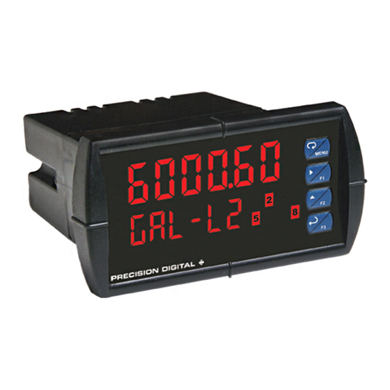
Display Features 0.6
Six Full Digits on Each Line
Optional Superluminous Sunlight Readable Display
Free USB Programming Software & Cable
2 or 4 Relays + Isolated 4-20 mA Output Options
USB, RS-232, & RS-485 Serial Communication Options
External 4-Relay & Digital I/O Expansion Modules
Input Power Options Include 85-265 VAC or 12-24 VDC
Modbus® RTU Communication Protocol Standard
Precision Digital Corporation
1.800.561.8187
P
V
PD6100 Strain Gauge, Load Cell & mV Meter
RO
U
Instruction Manual
" & 0.46"
www.
Digits
.com
P
V
R
S
ERIES
USB Install
Strain Gauge
information@itm.com
U
®
Advertisement
Table of Contents
Troubleshooting

Related Manuals for PRECISION DIGITAL ProVu Series


Summary of Contents for PRECISION DIGITAL ProVu Series
- Page 1 2 or 4 Relays + Isolated 4-20 mA Output Options USB, RS-232, & RS-485 Serial Communication Options External 4-Relay & Digital I/O Expansion Modules Input Power Options Include 85-265 VAC or 12-24 VDC Modbus® RTU Communication Protocol Standard Precision Digital Corporation 1.800.561.8187 information@itm.com www. .com...
- Page 2 Disclaimer The information contained in this document is subject to change without notice. Precision Digital makes no representations or warranties with respect to the contents hereof and specifically disclaims any implied warranties of merchantability or fitness for a particular purpose.
-
Page 3: Table Of Contents
PD6100 Strain Gauge, Load Cell, & mV Meter Instruction Manual Table of Contents Table of Contents ..........3 High Alarm Operation (Set > Reset) ...... 33 Table of Figures ............ 4 Low Alarm Operation (Set < Reset) ....... 33 ... -
Page 4: Table Of Figures
PD6100 Strain Gauge, Load Cell, & mV Meter Instruction Manual Table of Figures Figure 1. 1/8 DIN Panel Cutout Dimensions ....10 Figure 12. mV Transducer Input Connections ..15 Figure 2. Panel Mounting Details ....... 10 Figure 13. -
Page 5: Ordering Information
PD6100 Strain Gauge, Load Cell, & mV Meter Instruction Manual Ordering Information Standard Models 85-265 VAC Model 12-24 VDC Model Options Installed PD6100-6R0 PD6100-7R0 No options PD6100-6R2 PD6100-7R2 2 relays (PD1102*) PD6100-6R3 PD6100-7R3 4-20 mA output (PD1103*) PD6100-6R4 PD6100-7R4 4 relays (PD1104*) PD6100-6R5 PD6100-7R5 2 relays &... -
Page 6: Specifications
PD6100 Strain Gauge, Load Cell, & mV Meter Instruction Manual Specifications Except where noted all specifications apply to operation at +25°C. Power 85-265 VAC 50/60 Hz, 90-265 VDC, General 20 W max or 12-24 VDC 10%, 15 W Options max. -
Page 7: Strain Gauge Input
PD6100 Strain Gauge, Load Cell, & mV Meter Instruction Manual Strain Gauge Input Relays Inputs Field selectable: 0-15, 0-30, 0-150, Rating 2 or 4 SPDT (Form C) internal and/or 0-300 mV, ±15, ±25, ±150, ±250 4 SPST (Form A) external; rated 3 A mV, or Modbus PV (Slave) @ 30 VDC and 125/250 VAC resistive load;... -
Page 8: Isolated 4-20 Ma Transmitter Output
PD6100 Strain Gauge, Load Cell, & mV Meter Instruction Manual ® Isolated 4-20 mA Transmitter Output Modbus RTU Serial Communications Output Source Process variable (PV), max, min, set Slave ID 1 – 247 (Meter address) points 1-8, Modbus input, or manual Baud Rate 300 –... -
Page 9: Compliance Information
PD6100 Strain Gauge, Load Cell, & mV Meter Instruction Manual Compliance Information Safety UL & c-UL Listed USA & Canada UL 508 Industrial Control Equipment UL File Number E160849 Front Panel UL Type 4X, NEMA 4X, IP65; panel gasket provided Low Voltage EN 61010-1:2010 Directive... -
Page 10: Safety Information
PD6100 Strain Gauge, Load Cell, & mV Meter Instruction Manual Safety Information CAUTION: Read complete WARNING: Risk of electric instructions prior to installation shock or personal injury. and operation of the meter. Hazardous voltages exist within enclosure. Installation and service should be performed WARNING! only by trained service personnel. -
Page 11: Mounting Dimensions
PD6100 Strain Gauge, Load Cell, & mV Meter Instruction Manual Mounting Dimensions Figure 3. Meter Dimensions - Side View Figure 4. Meter Dimensions - Top View Sensor Excitation Voltage Selection (EX+, EX-) All meters, including models equipped with the 12-24 VDC power option, are shipped from the factory configured to provide 10 VDC excitation for the sensor. -
Page 12: Connections
The connectors’ label, affixed to the meter, shows the location of all connectors available with requested configuration. Do not connect any equipment other than Precision Digital’s expansion modules, cables, or meters to the RJ45 M-LINK connector. Otherwise damage will occur to the equipment and the meter. -
Page 13: Signal Connections
PD6100 Strain Gauge, Load Cell, & mV Meter Instruction Manual Signal Connections Signal connections are made to a six-terminal connector labeled SIGNAL on Figure 6. The EX+ and EX- terminals are used to sense the sensor excitation voltage for ratiometric operation, when the sensor is powered externally (switch 1 is off). -
Page 14: Figure 9. Strain Gauge Powered By Internal Supply
PD6100 Strain Gauge, Load Cell, & mV Meter Instruction Manual Shunt Resistor (Switch 5) The PD6100 provides a means of simulating strain in a strain gauge bridge circuit via a 60.4KΩ shunt resistor included in the meter. This will simulate an approximate 70% full-scale load in the case of a 350Ω strain bridge. -
Page 15: Shunt Calibration
PD6100 Strain Gauge, Load Cell, & mV Meter Instruction Manual NOTE: Refer to Switch Configuration starting on page 13 for proper switch positioning for the following wiring configurations. When connecting multiple strain gauges to the meter, each must be wired in parallel. This is typically done with the use of a junction box. -
Page 16: Modbus Rtu Serial Communications
Figure 16. Low Voltage DC Loads Protection RC Networks Available from Precision Digital RC networks are available from Precision Digital and should be applied to each relay contact switching an inductive load. Part number: PDX6901. Note: Relays are de-rated to 1/14th HP (50 watts) with an inductive load. -
Page 17: 4-20 Ma Output Connections
PD6100 Strain Gauge, Load Cell, & mV Meter Instruction Manual 4-20 mA Output Connections Connections for the 4-20 mA transmitter output are made to the connector terminals labeled MA OUT. The 4-20 mA output may be powered internally or from an external power supply. 24 V 24 V MA OUT... -
Page 18: External Relays & Digital I/O Connections
PD6100 Strain Gauge, Load Cell, & mV Meter Instruction Manual External Relays & Digital I/O Connections The relay and the digital I/O expansion modules PDA1004 & PDA1044 are connected to the meter using a CAT5 cable provided with each module. The two RJ45 connectors on the expansion modules are identical and interchangeable;... -
Page 19: Setup And Programming
PD6100 Strain Gauge, Load Cell, & mV Meter Instruction Manual Setup and Programming The meter is factory calibrated prior to shipment to read in millivolts. The calibration equipment is certified to NIST standards. Overview There is a 5-position DIP switch to set the meter input selection. See Figure 8 on page 13 to setup the switch. -
Page 20: Meterview ® Pro Software
PD6100 Strain Gauge, Load Cell, & mV Meter Instruction Manual ® MeterView Pro Software The meter can also be programmed using the PC-based MeterView Pro software included with the meter. This software can be installed on any Microsoft® Windows® (XP/Vista/7/8/10) computer by connecting the meter’s onboard USB. -
Page 21: Display Functions & Messages
PD6100 Strain Gauge, Load Cell, & mV Meter Instruction Manual Display Functions & Messages The meter displays various functions and messages during setup, programming, and operation. The following table shows the main menu functions and messages in the order they appear in the menu. Display Parameter Action/Setting... - Page 22 PD6100 Strain Gauge, Load Cell, & mV Meter Instruction Manual Action/Setting Action/Setting Display Parameter Display Parameter Description Description Set relay for latching Program display 2 Lt-CLr Dis 2 Latching- Display 2 operation with manual value cleared reset only after alarm Program output 2 Out 2 Output 2...
-
Page 23: Setting Numeric Values
PD6100 Strain Gauge, Load Cell, & mV Meter Instruction Manual Setting Numeric Values The numeric values are set using the Right and Up arrow buttons. Press Right arrow to select next digit and Up arrow to increment digit value. The digit being changed is displayed brighter than the rest. Press and hold up arrow to auto-increment the display value. -
Page 24: Setting Up The Meter (Setup)
PD6100 Strain Gauge, Load Cell, & mV Meter Instruction Manual Setting Up the Meter (setup) The Setup menu is used to select: 1. Unipolar (e.g. 0-30 mV) or bipolar (e.g. ±25 mV) polarity, input range, ratiometric operation, and dual-scale feature 2. -
Page 25: Setting The Input Signal (Input)
PD6100 Strain Gauge, Load Cell, & mV Meter Instruction Manual Setting the Input Signal (Input) Enter the Input menu to set up the input polarity, range, ratiometric operation, and dual-scale feature. The meter is capable of accepting any signal from -250 to 250 mV in bipolar mode or up to 300 mV in unipolar mode. -
Page 26: Setting The Input Units (Units)
PD6100 Strain Gauge, Load Cell, & mV Meter Instruction Manual Setting the Input Units (units) Enter the pre-defined engineering unit or custom unit. The pre-defined units have automatic conversion factors. This unit will be displayed if d unit is selected as the lower display parameter. See the flow chart on page 30 to access the display menu to show the unit on the lower display. -
Page 27: Setting The Input Units Or Custom Tags (Units)
PD6100 Strain Gauge, Load Cell, & mV Meter Instruction Manual Setting the Input Units or Custom Tags (units) Enter the input unit or custom tag that will be displayed if units are selected in the units menu, or d unit is selected as the lower display parameter. See the flow chart on page 30 to access the display menu to show the unit or tag on the lower display. -
Page 28: Programming The Meter (Prog)
PD6100 Strain Gauge, Load Cell, & mV Meter Instruction Manual Programming the Meter (prog) The Program menu contains the Scale and the Calibrate menus. For strain gauge and load cell applications it is recommended to calibrate the meter using the sensor as the input and with ratiometric operation enabled to compensate for small variation in the excitation voltage. - Page 29 PD6100 Strain Gauge, Load Cell, & mV Meter Instruction Manual Multi-Point Calibration & Scaling The meter is set up at the factory for 2-point linear calibration. The number of points for multi-point calibration/scaling is set up in the Advanced Features menu. Up to 32 linearization points may be selected for PV1 and up to 8 linearization points may be selected for PV2.
-
Page 30: Setting The Display Parameter & Intensity (Dsplay)
PD6100 Strain Gauge, Load Cell, & mV Meter Instruction Manual Setting the Display Parameter & Intensity (dsplay) Display line 1 (line 1) can be programmed to display: 1. Process value 1 (PV1) 2. Process value 2 (PV2) 3. Percent of PV1 (PCt) 4. -
Page 31: Setting The Relay Operation (Relay)
PD6100 Strain Gauge, Load Cell, & mV Meter Instruction Manual Setting the Relay Operation (relay) This menu is used to set up the operation of the relays. During setup, the relays do not follow the input and they will remain in the state Caution! found prior to entering the Relay menu. -
Page 32: Setting The Relay Action
PD6100 Strain Gauge, Load Cell, & mV Meter Instruction Manual Setting the Relay Action Operation of the relays is programmed in the Action menu. The relays may be set up for any of the following modes of operation: 1. Automatic reset (non-latching) 2. -
Page 33: Programming Set And Reset Points
PD6100 Strain Gauge, Load Cell, & mV Meter Instruction Manual Programming Set and Reset Points High alarm indication: program set point above reset point. Low alarm indication: program set point below reset point. The deadband is determined by the difference between set and reset points. -
Page 34: High Alarm With Fail-Safe Operation (Set > Reset)
PD6100 Strain Gauge, Load Cell, & mV Meter Instruction Manual High Alarm with Fail-Safe Low Alarm with Fail-Safe Operation Operation (Set > Reset) (Set < Reset) Note: Relay coil is energized in non-alarm condition. In case of power failure, relay will go to alarm state. Pump Alternation Control Operation 1.800.561.8187 information@itm.com... -
Page 35: Relay Sampling Operation
PD6100 Strain Gauge, Load Cell, & mV Meter Instruction Manual Relay Sampling Operation Input Reset Sample Sample Sample Time Time Time Relay When the signal crosses the set point, the relay trips and the sample time starts. After the sample time has elapsed, the relay resets. -
Page 36: Relay Operation Details
PD6100 Strain Gauge, Load Cell, & mV Meter Instruction Manual Relay Operation Details Overview The relay capabilities of the meter expand its usefulness beyond simple indication to provide users with alarm and control functions. These capabilities include front panel alarm status LEDs as well as either 2 or 4 optional internal relays and/or 4 external relays expansion module. -
Page 37: Latching And Non-Latching Relay Operation
PD6100 Strain Gauge, Load Cell, & mV Meter Instruction Manual Latching and Non-Latching Relay Operation The relays can be set up for latching (manual reset) or Relay terminology for following tables non-latching (automatic reset) operation. Terminology Relay Condition The On and Off terminology does not refer to the status of Alarm (Tripped) the relay’s coil, which depends on the fail-safe mode Normal (Reset) -
Page 38: Acknowledging Relays
PD6100 Strain Gauge, Load Cell, & mV Meter Instruction Manual Acknowledging Relays There are two ways to acknowledge relays programmed for manual reset: 1. Via the programmable front panel function keys F1-F3 (Assignable via the User menu inside the Advanced Features menu. 2. - Page 39 PD6100 Strain Gauge, Load Cell, & mV Meter Instruction Manual Application #2: Pump Alternation Using Relays 3 & 4 1. Relays 1 and 2 are set up for low and high alarm indication. 2. Relays 3 and 4 are set up for pump alternation. Set and Reset Point Programming Relay Set Point...
-
Page 40: Setting Up The Interlock Relay (Force On) Feature
PD6100 Strain Gauge, Load Cell, & mV Meter Instruction Manual Setting Up the Interlock Relay (Force On) Feature Relays 1-4 can be set up as interlock relays. To set up the relays for the interlock feature: 1. Access the Setup – Relay – Action menu and set the action to off. 2. -
Page 41: Setting Up The Password (Pass)
PD6100 Strain Gauge, Load Cell, & mV Meter Instruction Manual Setting Up the Password (pass) The Password menu is used for programming three levels of security to prevent unauthorized changes to the programmed parameter settings. Pass 1: Allows use of function keys and digital inputs Pass 2: Allows use of function keys, digital inputs and editing set/reset points Pass 3: Restricts all programming, function keys, and digital inputs. -
Page 42: Reset Menu (Reset)
PD6100 Strain Gauge, Load Cell, & mV Meter Instruction Manual Reset Menu (reset) The Reset menu is used to reset the tare (rst tr) and the maximum or minimum readings (peak or valley) reached by the process; max & min may be reset at the same time by selecting “reset high & low” (rst HL). -
Page 43: Advanced Features Menu
PD6100 Strain Gauge, Load Cell, & mV Meter Instruction Manual Advanced Features Menu To simplify the setup process, functions not needed for most applications are located in the Advanced Features menu. Press and hold the Menu button for three seconds to access the advanced features of the meter. Advanced Features Menu &... -
Page 44: Noise Filter (Filter)
PD6100 Strain Gauge, Load Cell, & mV Meter Instruction Manual Display Parameter Action/Setting Display Parameter Action/Setting Assign function keys and Calibrate 150 mV input user 100nmv User I/O 100 mV digital I/O range (internal reference calibration source used for scaling the Assign F1 function key F1 function input) -
Page 45: Modbus Rtu Serial Communications (Serial)
RS-232, or RS-485 option is required; see Ordering Information on page 5 for details. Do not connect any equipment other than Precision Digital’s expansion modules, cables, or meters to the RJ45 M-LINK connector. Otherwise damage will occur to the equipment and the Warning! meter. -
Page 46: Auto-Zero (Auto 0)
PD6100 Strain Gauge, Load Cell, & mV Meter Instruction Manual Multi-Point Linearization (Linear) Meters are set up at the factory for linear function with 2-point linearization. Up to 32 linearization points can be selected for PV under the linear function. The multi-point linearization can be used to linearize the display for non-linear signals such as those from level Sensors used to measure volume in odd-shaped tanks or to convert level to flow using weirs and flumes with complex exponent. -
Page 47: Programmable Function Keys User Menu ( )
PD6100 Strain Gauge, Load Cell, & mV Meter Instruction Manual Analog Output Calibration To perform the analog output calibration, it is recommended to use a milliamp meter with a resolution of at least 0.1 µA to measure the output current. The values saved internally during this procedure are used for scaling the 4-20 mA output in the Setup menu. -
Page 48: Internal Source Calibration (Ical)
PD6100 Strain Gauge, Load Cell, & mV Meter Instruction Manual Display Description Display Description Mimic the menu button functionality Mimic the enter/F3 button nmenu Enter (digital inputs only) functionality (digital inputs only) Mimic the right arrow/F1 button Provide indication when alarm 1 rigHt Alnm 1 functionality (digital inputs only) -
Page 49: Error Message (Error)
PD6100 Strain Gauge, Load Cell, & mV Meter Instruction Manual Tips: Low and high input signals can be any valid values within the range of the meter. Observe minimum input span requirements between input 1 and input 2. ... -
Page 50: Meter Operation
PD6100 Strain Gauge, Load Cell, & mV Meter Instruction Manual Meter Operation The meter is capable of accepting any signal from -250 to 250 mV in bipolar mode, or 0 to 300 mV in unipolar mode, and displaying these signals in engineering units from -99999 to 999999 (e.g. a 0-100 mV signal could be displayed as 0 to 50000). -
Page 51: Maximum/Minimum Readings
PD6100 Strain Gauge, Load Cell, & mV Meter Instruction Manual Maximum/Minimum Readings The max & min readings (peak & valley) reached by the process can be displayed either continuously or momentary: 1. Display briefly by assigning to the F1-F3 function keys or to the digital inputs in the User menu. Any of the F1-F3 function keys (buttons) and the digital inputs can be programmed to reset the max &... -
Page 52: Troubleshooting
PD6100 Strain Gauge, Load Cell, & mV Meter Instruction Manual Troubleshooting Due to the many features and functions of the meter, it’s possible that the setup of the meter does not agree with what an operator expects to see. If the meter is not working as expected, refer to the Diagnostics menu and consult the recommendations described below. -
Page 53: Factory Defaults & User Settings
PD6100 Strain Gauge, Load Cell, & mV Meter Instruction Manual Factory Defaults & User Settings The following table shows the factory setting for most of the programmable parameters on the meter. Parameter Display Default Setting Parameter Display Default Setting Polar = Uni Fail-safe relay 1 Fls 1 Input type... -
Page 54: Troubleshooting Tips (Including Fault & Error Messages)
PD6100 Strain Gauge, Load Cell, & mV Meter Instruction Manual Parameter Display Default Setting Parameter Display Default Setting Digital input 4 Enter/F3 Digital output 4 Alarm 4 dI 4 dO 4 Digital output 1 dO 1 Alarm 1 Password 1 Pass 1 000000 (unlocked) Digital output 2... -
Page 55: Eu Declaration Of Conformity
EN 55022:2010, EN 61000-6- 2:2005, EN 61010-1:2010, and EN 61326:2013 and there were no major technical changes affecting the latest technical knowledge for the products listed above. Product Markings: Signed for and on behalf of Precision Digital Corporation: Name: Jeffrey Peters Company:... - Page 56 PD6100 Strain Gauge, Load Cell, & mV Meter Instruction Manual PRECISION DIGITAL CORPORATION LIM6100_F SFT071 Ver 4.000 & up 03/17 1.800.561.8187 information@itm.com www. .com...
Need help?
Do you have a question about the ProVu Series and is the answer not in the manual?
Questions and answers