Table of Contents
Advertisement
Quick Links
• Thermocouple: J, K, T, E, R, S, B, N, C
• RTD: 100Ω Pt, 10Ω Cu, 120Ω Ni, 1000Ω Pt inputs
• 1° or 0.1° Resolution
• Displays up to 3300 F
• Averages up to 10 RTD Sensors
• Automatic Cold Junction Compensation
• Modern, Sleek and Practical Enclosure
• Display Mountable at 0°, 90°, 180°, & 270° Degrees
• Explosion-Proof, IP68, NEMA 4X Enclosure
• SafeTouch
• Flanges for Wall or Pipe Mounting
• Superluminous Sunlight Readable Display
• Free USB Programming Software & Cable
• 4 Relays + Isolated 4-20 mA Output Option
• USB, RS-232, & RS-485 Serial Communication Options
• Input Power Options Include 85-265 VAC or 12-24 VDC
PRECISION DIGITAL CORPORATION
1.800.561.8187
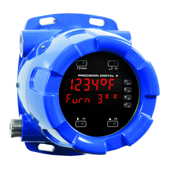
ProtEX-MAX PD8-7000 Explosion-Proof
Temperature Meter Instruction Manual
®
Through-Glass Button Programming
www.
Temperature
information@itm.com
.com
USB Install
Advertisement
Table of Contents
Troubleshooting

Related Manuals for PRECISION DIGITAL ProtEX-MAX PD8-7000


Summary of Contents for PRECISION DIGITAL ProtEX-MAX PD8-7000
- Page 1 ProtEX-MAX PD8-7000 Explosion-Proof Temperature Meter Instruction Manual USB Install Temperature • Thermocouple: J, K, T, E, R, S, B, N, C • RTD: 100Ω Pt, 10Ω Cu, 120Ω Ni, 1000Ω Pt inputs • 1° or 0.1° Resolution • Displays up to 3300 F •...
- Page 2 Precision Digital Corporation warrants this product against defects in material or workmanship for the specified period under “Specifications” from the date of shipment from the factory. Precision Digital’s liability under this limited warranty shall not exceed the purchase value, repair, or replacement of the defective unit.
-
Page 3: Table Of Contents
ProtEX-MAX PD8-7000 Explosion-Proof Temperature Meter Instruction Manual Table of Contents Table of Contents ----------------------------------------- 3 Setting the Relay Action ---------------------------------- 31 Table of Figures ------------------------------------------- 4 Programming Set and Reset Points ------------------ 31 Setting Fail-Safe Operation ----------------------------- 31 Introduction ------------------------------------------------- 4... -
Page 4: Table Of Figures
Figure 12: RS-485 Two-Wire Multi-Drop Wiring ..18 Introduction The ProtEX-MAX PD8-7000 offers all the functionality of the ProVu PD7000 as a fully FM, CSA, ATEX, and IECEx approved explosion-proof product. It accepts a direct temperature input from a wide range of temperature measurement devices (type J, K, T, E, R, S, B, N, and C thermocouples and 100 or 1000 Ω... -
Page 5: Ordering Information
ProtEX-MAX PD8-7000 Explosion-Proof Temperature Meter Instruction Manual Ordering Information SunBright Display Models 85-265 VAC Model 12-24 VDC Model Options Installed PD8-7000-6H0 PD8-7000-7H0 No options PD8-7000-6H7 PD8-7000-7H7 4 relays & 4-20 mA output WARNING - Cancer and Reproductive Harm - www.P65Warnings.ca.gov... -
Page 6: Specifications
ProtEX-MAX PD8-7000 Explosion-Proof Temperature Meter Instruction Manual Specifications Except where noted all specifications apply to operation at +25°C. General Max Power Maximum power dissipation limited to 15.1 Dissipation Line 1: 0.60" (15 mm) high red LEDs; Display Connections Screw terminals accept 12 to 22 AWG wire Line 2: 0.46"... -
Page 7: Temperature Input
ProtEX-MAX PD8-7000 Explosion-Proof Temperature Meter Instruction Manual Temperature Input Relays Inputs Thermocouple: J, K, T, E, R, S, B, N, C; Rating 4 SPDT (Form C) internal and/or 4 SPST RTD: 100 Ω platinum (0.00385 & 0.00392 (Form A) external; rated 3 A @ 30 VDC and coefficients), 125/250 VAC resistive load;... -
Page 8: Isolated 4-20 Ma Output
ProtEX-MAX PD8-7000 Explosion-Proof Temperature Meter Instruction Manual Isolated 4-20 mA Output Digital Inputs & Outputs 4 digital inputs & 4 digital outputs per Channels Output PV (temperature), max, min, set points 1-4, module Source Modbus PV input, or manual control mode... -
Page 9: Product Ratings And Approvals
ProtEX-MAX PD8-7000 Explosion-Proof Temperature Meter Instruction Manual Product Ratings and Approvals; Enclosure: Type 4X; IP66 Class I, Division 1, Groups B, C, D Class II, Division 1, Groups E, F, G Class III, Division 1, T5/T6 Class I, Zone 1, AEx d, IIC Gb T5/T6 Zone 21, AEx tb IIIC T90°C;... -
Page 10: Compliance Information
ProtEX-MAX PD8-7000 Explosion-Proof Temperature Meter Instruction Manual Compliance Information Safety UL & c-UL Listed USA & Canada UL 508 Industrial Control Equipment UL File Number E160849 Front Panel UL Type 4X, NEMA 4X, IP65; panel gasket provided Low Voltage EN 61010-1:2010... -
Page 11: Safety Information
ProtEX-MAX PD8-7000 Explosion-Proof Temperature Meter Instruction Manual Safety Information WARNINGS • Read complete instructions prior to installation and operation of the instrument. • Installation and service should be performed only by trained service personnel. Service requiring replacement of internal sub-components must be performed at the factory. -
Page 12: Pre-Installed Conduit/Stopping Plug
ProtEX-MAX PD8-7000 Explosion-Proof Temperature Meter Instruction Manual Pre-Installed Conduit/Stopping Plug The PD8-6000 is supplied with two pre-installed conduit plugs for installations that do not require the use of all conduit entries. The conduit/stopping plugs include an internal 12mm hexagonal socket recess for removal. -
Page 13: Connections
ProtEX-MAX PD8-7000 Explosion-Proof Temperature Meter Instruction Manual Connections • Static electricity can damage sensitive components. • Observe safe handling precautions for static-sensitive components. • Use proper grounding procedures/codes. • If the instrument is installed in a high voltage environment and a... -
Page 14: Connectors Labeling
ProtEX-MAX PD8-7000 Explosion-Proof Temperature Meter Instruction Manual Connectors Labeling The connectors’ label, affixed to the meter, shows the location of all connectors available with requested configuration. Do not connect any equipment other than Precision Digital’s expansion modules, cables, or meters to the RJ45 M-LINK connector. -
Page 15: Signal Connections
ProtEX-MAX PD8-7000 Explosion-Proof Temperature Meter Instruction Manual Signal Connections Signal connections are made to a three-terminal connector labeled SIGNAL on Figure 2. Thermocouple and RTD Connections The following figures show examples for thermocouple and RTD connections. The TYPE selector switch must be set to the proper position for the meter to accept the selected RTD or TC input. -
Page 16: Connections For Averaging Rtd Sensors
ProtEX-MAX PD8-7000 Explosion-Proof Temperature Meter Instruction Manual Connections for Averaging RTD Sensors To obtain the average temperature from 2 to 10 RTD sensors, connect all the sensors in parallel and select the number of sensors in the RTD Total (rtdtot) menu. See the Advanced Features Menu on page 40. -
Page 17: Figure 11: Rs-485 Wiring
ProtEX-MAX PD8-7000 Explosion-Proof Temperature Meter Instruction Manual Figure 11: RS-485 Wiring Notes: 1. Termination resistors are optional and values depend on the cable length and characteristic im- pedance. Consult the cable manufacturer for recommendations. 2. Refer to RS-232 to RS-485 Converter documentation for further details. -
Page 18: Using Pro Vu U Serial Adapters
ProtEX-MAX PD8-7000 Explosion-Proof Temperature Meter Instruction Manual Figure 12: RS-485 Two-Wire Multi-Drop Wiring Notes: 1. Termination resistors are optional and values depend on the cable length and characteristic im- pedance. Consult the cable manufacturer for recommendations. 2. Refer to RS-232 to RS-485 Converter documentation for further details. -
Page 19: Relay Connections
Figure 15. Low Voltage DC Loads Protection RC Networks Available from Precision Digital RC networks are available from Precision Digital and should be applied to each relay contact switching an inductive load. Part number: PDX6901. Note: Relays are de-rated to 1/14th HP (50 watts) with an inductive load. -
Page 20: F4 Digital Input Connections
ProtEX-MAX PD8-7000 Explosion-Proof Temperature Meter Instruction Manual F4 Digital Input Connections A digital input, F4, is standard on the meter. This digital input connected with a normally open closure across F4 and COM, or with an active low signal applied to F4. -
Page 21: Digital I/O Connections
ProtEX-MAX PD8-7000 Explosion-Proof Temperature Meter Instruction Manual Digital I/O Connections The ProtEX-MAX has a 10 position terminal block for connecting digital inputs and outputs. 5 VDC DI 1-4 DO 1-4 Figure 19: Digital I/O Connections The onboard digital inputs (1-4) are configured at the factory to function identically to the front panel pushbuttons (Menu, F1, F2, &... -
Page 22: Setup And Programming
ProtEX-MAX PD8-7000 Explosion-Proof Temperature Meter Instruction Manual Setup and Programming The meter is factory calibrated prior to shipment to read temperature in degrees Fahrenheit. The calibration equipment is traceable to NIST standards. Overview There are two switches, located at the back of the meter, to set the input selection for TC or RTD and for 100-ohm platinum or 10-ohm copper. -
Page 23: Front Buttons And Status Led Indicators
ProtEX-MAX PD8-7000 Explosion-Proof Temperature Meter Instruction Manual Front Buttons and Status LED Indicators Button Symbol Description Status Menu Alarm 1-8 indicator Flashing: Relay in Right arrow/F1 1-8-M manual control mode Manual control relays Up arrow/F2 &/or analog output Flashing: Relay... -
Page 24: Meterview ® Pro Software
ProtEX-MAX PD8-7000 Explosion-Proof Temperature Meter Instruction Manual MeterView Pro Software ® The meter can also be programmed using the PC-based MeterView Pro software included with the meter. This software can be installed on any Microsoft® Windows® (XP/Vista/7/8/10) computer by connecting the meter’s onboard USB. -
Page 25: Display Functions & Messages
ProtEX-MAX PD8-7000 Explosion-Proof Temperature Meter Instruction Manual Display Functions & Messages The meter displays various functions and messages during setup, programming, and operation. The following table shows the main menu functions and messages in the order they appear in the menu. - Page 26 ProtEX-MAX PD8-7000 Explosion-Proof Temperature Meter Instruction Manual Display Parameter Action/Setting Display Parameter Action/Setting Description Description Relay goes to non- Automatic Press Enter to set Auto alarm condition when meter for auto input break is operation detected Manual Press Enter to...
-
Page 27: Main Menu
ProtEX-MAX PD8-7000 Explosion-Proof Temperature Meter Instruction Manual Main Menu The main menu consists of the most commonly used functions: Setup, Reset, Control, and Password. • Press Menu button to enter Programming Mode then press the Up arrow button to scroll main menu. -
Page 28: Setting Up The Meter (Setup)
ProtEX-MAX PD8-7000 Explosion-Proof Temperature Meter Instruction Manual Setting Up the Meter (setup) It is very important to read the following information, before proceeding to program the meter: • The meter is factory calibrated prior to shipment to read temperature in degrees Fahrenheit. The calibration equipment is traceable to NIST standards. -
Page 29: Setting The Input Signal (Input)
ProtEX-MAX PD8-7000 Explosion-Proof Temperature Meter Instruction Manual Setting the Input Signal (Input) Enter the Input menu to set up the meter to accept thermocouple (tc) or RTD (rtd) inputs. The Type selector switch, located at the rear of the meter, must be set accordingly. -
Page 30: Setting The Input Units Or Custom Tags (Units)
ProtEX-MAX PD8-7000 Explosion-Proof Temperature Meter Instruction Manual Setting the Input Units or Custom Tags (units) Enter the input unit or custom tag that will be displayed if alternating rate, total, or grand total and units is selected in the units menu, or d unit is selected as the Lower display parameter. See the flow chart on page 29 to access the display menu to show the unit or tag on the Lower display. -
Page 31: Setting The Relay Action
ProtEX-MAX PD8-7000 Explosion-Proof Temperature Meter Instruction Manual Setting the Relay Action Operation of the relays is programmed in the Action menu. The relays may be set up for any of the following modes of operation: 1. Automatic reset (non-latching) 2. Automatic + manual reset at any time (non-latching) 3. -
Page 32: Relay And Alarm Operation Diagrams
ProtEX-MAX PD8-7000 Explosion-Proof Temperature Meter Instruction Manual Relay and Alarm Operation Diagrams The following graphs illustrate the operation of the relays, status LEDs, and ACK button. High Alarm Operation (Set > Reset) Low Alarm Operation (Set < Reset) For Manual reset mode, ACK can be pressed anytime For Manual reset mode, ACK can be pressed anytime to turn "off"... -
Page 33: Pump Alternation Control Operation
ProtEX-MAX PD8-7000 Explosion-Proof Temperature Meter Instruction Manual Pump Alternation Control Operation Relay Sampling Operation Input Reset Sample Sample Sample Time Time Time Relay When the signal crosses the set point, the relay trips and the sample time starts. After the sample time has elapsed, the relay resets. -
Page 34: Signal Loss Or Input Break Relay Operation
ProtEX-MAX PD8-7000 Explosion-Proof Temperature Meter Instruction Manual Signal Loss or Input Break Relay Operation The following graph shows the input break relay operation for a high alarm relay. Input INPUT BREAK INPUT BREAK Reset de-energized energized Relay Input Break = Ignore... -
Page 35: Relay Operation Details
ProtEX-MAX PD8-7000 Explosion-Proof Temperature Meter Instruction Manual Relay Operation Details Overview The relay capabilities of the meter expand its usefulness beyond simple indication to provide users with alarm and control functions. These capabilities include front panel alarm status LEDs as well as either 2 or 4 optional internal relays. -
Page 36: Latching And Non-Latching Relay Operation
ProtEX-MAX PD8-7000 Explosion-Proof Temperature Meter Instruction Manual Latching and Non-Latching Relay Operation The relays can be set up for latching (manual reset) or Relay terminology for following tables non-latching (automatic reset) operation. Terminology Relay Condition Alarm (Tripped) The On and Off terminology does not refer to the status of Normal (Reset) the relay’s coil, which depends on the fail-safe mode... -
Page 37: Acknowledging Relays
ProtEX-MAX PD8-7000 Explosion-Proof Temperature Meter Instruction Manual Acknowledging Relays There are two ways to acknowledge relays programmed for manual reset: Via the programmable front panel function keys F1-F3 (Default: F3 assigned to ACK). Remotely via a normally open pushbutton wired across one of the digital inputs and the +5 V terminals on the digital I/O modules, or using the F4 digital input, which is triggered with a contact closure to COM, or with an active low signal (see page 20). -
Page 38: Scaling The 4-20 Ma Analog Output (Aout)
ProtEX-MAX PD8-7000 Explosion-Proof Temperature Meter Instruction Manual Scaling the 4-20 mA Analog Output (Aout) The 4-20 mA analog output can be scaled to provide a 4-20 mA signal for any display range selected. No equipment is needed to scale the analog output; simply program the display values to the corresponding mA output signal. -
Page 39: Setting Up The Password (Pass)
ProtEX-MAX PD8-7000 Explosion-Proof Temperature Meter Instruction Manual Setting Up the Password (pass) The Password menu is used for programming three levels of security to prevent unauthorized changes to the programmed parameter settings. Pass 1: Allows use of function keys and digital inputs Pass 2: Allows use of function keys, digital inputs and editing set/reset points Pass 3: Restricts all programming, function keys, and digital inputs. -
Page 40: Advanced Features Menu
ProtEX-MAX PD8-7000 Explosion-Proof Temperature Meter Instruction Manual Advanced Features Menu To simplify the setup process, functions not needed for most applications are located in the Advanced Features menu. Press and hold the Menu button for three seconds to access the advanced features of the meter. -
Page 41: Offset Adjust (Adjust)
ProtEX-MAX PD8-7000 Explosion-Proof Temperature Meter Instruction Manual Display Parameter Action/Setting Display Parameter Action/Setting Underrange Program mA output F3 function Assign F3 function u-rang for display underrange F4 function Assign F4 function (digital input) Loop Break Set relay condition if Break... -
Page 42: Recalibration Of The Meter (T Cal)
ProtEX-MAX PD8-7000 Explosion-Proof Temperature Meter Instruction Manual Recalibration of the Meter (t CAL) The Calibration (t CAL) menu is used to recalibrate the thermocouple and RTD inputs. • The meter is factory calibrated prior to shipment to read temperature in degrees Fahrenheit. -
Page 43: Noise Filter (Filter)
ProtEX-MAX PD8-7000 Explosion-Proof Temperature Meter Instruction Manual Noise Filter (filter) The noise filter is available for unusually noisy signals that cause an unstable process variable display. The noise filter averages the input signal over a certain period. The filter level determines the length of time over which the signal is averaged. -
Page 44: Serial Communications Overview
ProtEX-MAX PD8-7000 Explosion-Proof Temperature Meter Instruction Manual Serial Communications Overview RS-232 and RS-485 are standard interfaces approved by the Electronic Industries Alliance (EIA) for con- necting serial devices. In EIA terms, the device (e.g. meter) that connects to the interface is called a Data Communications Equipment (DCE) and the device to which it connects (e.g. -
Page 45: Select Menu (Select)
ProtEX-MAX PD8-7000 Explosion-Proof Temperature Meter Instruction Manual Select Menu (SElect) The Select menu is used to program the analog output parameters. There are no other selections for this model. Analog Output Programming (AoutPr) The Analog Output Programming menu is used to program the behavior of the 4-20 mA output. The following parameters and functions are programmed in this menu: 1. -
Page 46: Programmable Function Keys User Menu (User)
ProtEX-MAX PD8-7000 Explosion-Proof Temperature Meter Instruction Manual Programmable Function Keys User Menu (user) The User menu allows the user to assign the front panel function keys F1, F2, and F3, the digital input F4 (a digital input located on the signal input connector), and up to eight additional digital inputs to access most of the menus or to activate certain functions immediately (e.g. -
Page 47: Internal Temperature Calibration (Ical)
ProtEX-MAX PD8-7000 Explosion-Proof Temperature Meter Instruction Manual Internal Temperature Calibration (ICAL) The meter is factory calibrated prior to shipment to read temperature in degrees Fahrenheit. The calibration equipment is traceable to NIST standards. The Internal Calibration (ICAL) is a function used at the factory to calibrate all the thermocouple and RTD ranges. -
Page 48: 1.800.561.8187 Www. .Com
ProtEX-MAX PD8-7000 Explosion-Proof Temperature Meter Instruction Manual RTD Input Internal Calibration (ICAL) 1. Set the Type selector switch in the RTD position and the Range switch in the 10 position. Using 3 wires connect a precision calibrator resistance output to the meter. -
Page 49: Meter Operation
ProtEX-MAX PD8-7000 Explosion-Proof Temperature Meter Instruction Manual Meter Operation The meter is capable of accepting a variety of thermocouples and RTDs. The dual-line display can be customized by the user to operate in such a way as to satisfy a specific application. -
Page 50: F4 Operation
ProtEX-MAX PD8-7000 Explosion-Proof Temperature Meter Instruction Manual F4 Operation A digital input, F4, is standard on the meter. This digital input is programmed identically to function keys F1, F2, and F3. The input is triggered with a contact closure to COM, or with an active low signal. During operation, F4 operates according to the way it has been programmed in the Advanced Features –... -
Page 51: Troubleshooting
ProtEX-MAX PD8-7000 Explosion-Proof Temperature Meter Instruction Manual Troubleshooting The rugged design and the user-friendly interface of the meter should make it unusual for the installer or operator to refer to this section of the manual. However, due to the many features and functions of the meter, it’s possible that the setup of the meter does not agree with what an operator expects to see. -
Page 52: Factory Defaults & User Settings
ProtEX-MAX PD8-7000 Explosion-Proof Temperature Meter Instruction Manual Factory Defaults & User Settings The following table shows the factory setting for most of the programmable parameters on the meter. Parameter Display Default Setting Parameter Display Default Setting Input break relay 2... -
Page 53: Troubleshooting Tips
ProtEX-MAX PD8-7000 Explosion-Proof Temperature Meter Instruction Manual Troubleshooting Tips Symptom Check/Action If mechanical button was pushed. The SafeTouch buttons will SafeTouch buttons do not respond be re-enabled automatically 60 seconds after the last button push. If slide switch on connector board is in DISABLE position, switch to ENABLE. -
Page 54: Service
ProtEX-MAX PD8-7000 Explosion-Proof Temperature Meter Instruction Manual Symptom Check/Action Check: Relay and status LED do not 1. Relay action in Setup menu respond to signal 2. Set and reset points Relays in manual control mode or relay interlock switches Flashing relay status LEDs opened. -
Page 55: Mounting Dimensions
ProtEX-MAX PD8-7000 Explosion-Proof Temperature Meter Instruction Manual Mounting Dimensions All units: inches (mm) Figure 23: Enclosure Dimensions – Front View Figure 24: Enclosure Dimensions – Side Cross Section View 1.800.561.8187 information@itm.com www. .com... - Page 56 ProtEX-MAX PD8-7000 Explosion-Proof Temperature Meter Instruction Manual This Page Intentionally Left Blank 1.800.561.8187 information@itm.com www. .com...
-
Page 57: Eu Declaration Of Conformity
SIRA 10 ATEX M462 ATEX Notified Body for Quality Assurance: Sira Certification Service, NB 0518 Unit 6, Hawarden Industrial Park Hawarden, Deeside, CH5 3US, UK Signed for and on behalf of Precision Digital Corporation: Name: Jeffrey Peters Company: Precision Digital Corporation... - Page 58 ProtEX-MAX PD8-7000 Explosion-Proof Temperature Meter Instruction Manual PRECISION DIGITAL CORPORATION LIM8-7000_C SFT063 Ver 4.000 & up 02/18 1.800.561.8187 information@itm.com www. .com...
Need help?
Do you have a question about the ProtEX-MAX PD8-7000 and is the answer not in the manual?
Questions and answers