Table of Contents
Advertisement
Quick Links
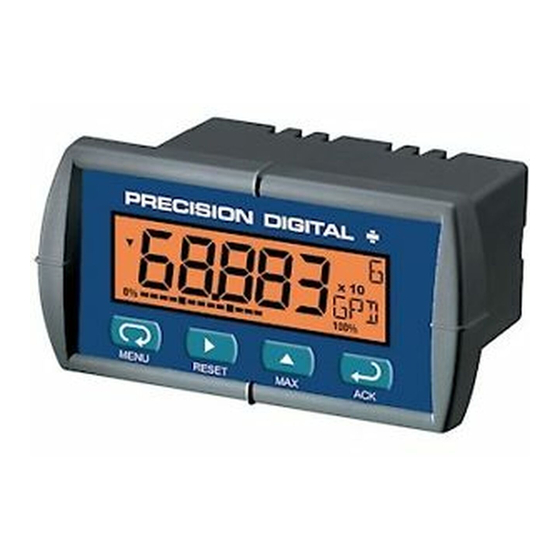
LOOP-POWERED METERS
•
2 V drop (5.7 V with backlight)
•
5-Digit LCD, 0.6" (15.2 mm) High
•
Custom Engineering Units
•
20-Segment Bargraph Display
•
Type 4X, NEMA 4X, IP65 Front
•
Maximum & Minimum Display
•
Linear, Square Root, or Programmable Exponent
•
Non-Volatile Memory – No Battery Needed
PRECISION DIGITAL CORPORATION
233 South Street • Hopkinton MA 01748 USA
Tel (800) 343-1001 • Fax (508) 655-8990
PD683 & PD688
Instruction Manual
PD688 only
Loop-
Powered
Backlight
Standard!
www.predig.com
Advertisement
Table of Contents

Related Manuals for PRECISION DIGITAL PD683


Summary of Contents for PRECISION DIGITAL PD683
- Page 1 PD683 & PD688 LOOP-POWERED METERS Instruction Manual PD688 only • 2 V drop (5.7 V with backlight) • 5-Digit LCD, 0.6" (15.2 mm) High Loop- Powered • Custom Engineering Units Backlight • 20-Segment Bargraph Display Standard! • Type 4X, NEMA 4X, IP65 Front •...
- Page 2 Disclaimer The information contained in this document is subject to change without notice. Precision Digital makes no representations or war- ranties with respect to the contents hereof, and specifically disclaims any implied warranties of merchantability or fitness for a particular purpose.
-
Page 3: Introduction
The square root and programmable exponent functions allow for condi- tioning of signals from non-linear transmitters without adding external components to the system and the convenience of scaling without a cali- brated signal source make the PD683 & PD688 the ideal choice for pro- cess display applications. ORDERING INFORMATION... -
Page 4: Table Of Contents
PD683 & PD688 Loop-Powered Meters Instruction Manual Table of Contents INTRODUCTION ------------------------------------------------------------ 3 ORDERING INFORMATION --------------------------------------------- 3 SPECIFICATIONS ---------------------------------------------------------- 6 General ------------------------------------------------------------------------------- 6 Input ----------------------------------------------------------------------------------- 7 PD688 COMPLIANCE INFORMATION ------------------------------- 8 Ratings and Approvals --------------------------------------------------------- 8 SAFETY INFORMATION ------------------------------------------------- 8... - Page 5 EU DECLARATION OF CONFORMITY FOR PD683 ------------ 39 Table of Figures Figure 1. Panel Cutout and Mounting ..........9 Figure 2. PD683 & PD688 Rear View ..........10 Figure 3. PD683 Input Connections with Backlight ......11 Figure 4. PD683 Input Connections without Backlight ....11 Figure 5.
-
Page 6: Specifications
PD683 & PD688 Loop-Powered Meters Instruction Manual SPECIFICATIONS Except where noted all specifications apply to operation at +25°C. General DISPLAY Five digits 0.60" (15.2 mm) high, 7-segment, au- (-99999 to 99999) tomatic lead zero blanking. Four characters 0.25" (6.4 mm) high, 14 segment. -
Page 7: Input
PD683 & PD688 Loop-Powered Meters Instruction Manual MOUNTING 1/8 DIN panel cutout required. Two panel mounting bracket assemblies provided TIGHTENING Screw terminal connectors: 4.5 lb-in (0.5 Nm) TORQUE Mounting screws: 8.0 lb-in max. (0.9 Nm) OVERALL 4.68" x 2.45" x 3.79" (119 mm x 62 mm x 96 mm) -
Page 8: Pd688 Compliance Information
PD683 & PD688 Loop-Powered Meters Instruction Manual PD688 COMPLIANCE INFORMATION Ratings and Approvals FM & CSA Certified as intrinsically safe with entity for use in: Class I, Div 1, 2, Groups ABCD Class II, Div 1, Groups EFG Class II, Div 2, Groups FG... -
Page 9: Installation
PD683 & PD688 Loop-Powered Meters Instruction Manual INSTALLATION There is no need to remove the meter from its case to com- plete the installation, wiring, and setup of the meter. Unpacking Remove the meter from box. Inspect the packaging and con- tents for damage. -
Page 10: Wiring Connections
Instruction Manual Wiring Connections Signal connections are made to a four-terminal removable connector. This section is only intended for the PD683. PD688 installation must be performed in accordance with Control Drawing LIM688-2 in order to meet agency approval ratings. Observe all safety regulations. Electrical wiring... -
Page 11: 4-20 Ma Input Connections
2.0 V as shown in Figure 4. S+ S- B+ B- 4-20 mA Transmitter Power Supply Figure 3. PD683 Input Connections with Backlight S+ S- B+ B- 4-20 mA Transmitter Power Supply Figure 4. PD683 Input Connections without Backlight... -
Page 12: Setup And Programming
PD683 & PD688 Loop-Powered Meters Instruction Manual SETUP AND PROGRAMMING • There is no need to recalibrate the meter for milliamps when first received from the factory. • The meter is factory calibrated for milliamps prior to shipment. The calibration equipment is certified to NIST standards. -
Page 13: Front Panel Buttons & Status Indicators
PD683 & PD688 Loop-Powered Meters Instruction Manual Front Panel Buttons & Status Indicators Button Description Symbol Status Symbol Bargraph Menu minimum Bargraph Right arrow/Reset 100% maximum Up arrow/Max Increasing trend Enter/Ack Decreasing trend • Press the Menu button to enter or exit the Programming Mode at any time. -
Page 14: Main Menu Display Functions & Messages
PD683 & PD688 Loop-Powered Meters Instruction Manual Main Menu Display Functions & Messages The meter displays various functions and messages during setup, pro- gramming, and operation. The following table shows the main menu functions and messages in the order they appear in the menu. -
Page 15: Main Menu
PD683 & PD688 Loop-Powered Meters Instruction Manual Main Menu The main menu consists of the most commonly used functions: Setup, Program, and Password. • Press Menu button to enter Programming Mode then press Up ar- row button to scroll main menu. -
Page 16: Setting Up The Meter (Setup)
PD683 & PD688 Loop-Powered Meters Instruction Manual Setting Up the Meter (setup) The Setup menu is used to select: Decimal point position Engineering units display Press the Enter/Ack button to access any menu or press Up arrow but- ton to scroll through choices. Press the Menu button to exit at any time. -
Page 17: Setting The Units Display (Units)
PD683 & PD688 Loop-Powered Meters Instruction Manual Setting the Units Display (units) The meter can be set to display a combination of three alphanumeric characters for engineering units or for identification (e.g. PSI, G/S, LpM, TK3, , L 7). There is also a fourth alphanumeric character located above this row, which supports a degrees symbol and “x10”... -
Page 18: Programming The Meter (Prog)
PD683 & PD688 Loop-Powered Meters Instruction Manual Programming the Meter (prog) It is very important to read the following information, before proceeding to program the meter: • There is no need to recalibrate the meter for milliamps when first received from the factory. -
Page 19: Scaling The Meter (Scale)
PD683 & PD688 Loop-Powered Meters Instruction Manual Scaling the Meter (sCalE) The 4-20 mA input can be scaled to display the process in engineering units. A signal source is not needed to scale the meter; simply program the in- puts and corresponding display values. -
Page 20: Calibrating The Meter (Cal)
PD683 & PD688 Loop-Powered Meters Instruction Manual Calibrating the Meter (Cal) To scale the meter without a signal source, refer to Scaling the Meter (sCalE), page 19. The meter can be calibrated to display the process in engineering units by applying the appropriate input signal and following the calibration procedure. -
Page 21: Setting Up The Bargraph (Graph)
PD683 & PD688 Loop-Powered Meters Instruction Manual Setting Up the Bargraph (GrapH) The meter can be set to display a bargraph proportional to the percent- age process reading within a user-defined span. The span is determined by values entered for 0% and 100%. -
Page 22: Setting Up The Password (Pass)
PD683 & PD688 Loop-Powered Meters Instruction Manual Setting Up the Password (pass) The Password menu is used to program a five-digit password to prevent unauthorized changes to the programmed parameter settings. Locking the Meter Enter the Password menu and program a five-digit password. -
Page 23: Unlocking The Meter
PD683 & PD688 Loop-Powered Meters Instruction Manual Unlocking the Meter If the meter is password protected, the correct password must be entered in order to make changes to the parameter settings. Run Mode pass locd 00000 unloc Enter Password Entering the correct five-digit number sets the password to 00000, disa- bling the protection. -
Page 24: Advanced Features Menu
PD683 & PD688 Loop-Powered Meters Instruction Manual Advanced Features Menu To simplify the setup process, functions not needed for most applica- tions are located in the Advanced Features menu. Press and hold the Menu button for five seconds to access the Ad- vanced Features of the meter. -
Page 25: Advanced Features Menu & Display Messages
PD683 & PD688 Loop-Powered Meters Instruction Manual Advanced Features Menu & Display Messages The following table shows the Advanced features menu functions and messages in the order they appear in the menu. Display Parameter Action/Setting Enter Function menu Funct Function... -
Page 26: Math Functions (Lnear, Squar, Prog. E , Cutof)
PD683 & PD688 Loop-Powered Meters Instruction Manual Math Functions (lnear, Squar, Prog. E , Cutof) The PD683 & PD688 provide a number of math functions to condition outputs from linear and non-linear transmitters. Press Enter to Accept Setting Advanced Features... -
Page 27: Contrast (Contr)
PD683 & PD688 Loop-Powered Meters Instruction Manual Contrast (contr) LCD contrast is adjustable through the front panel buttons. Select contr and increase level using Up Arrow/Max button. Settings 1 through 9 will be displayed on the screen as 11111 to 99999. Settings 1 through 4 are usually best when viewing from below the angle perpendicular to the display. -
Page 28: Internal Calibration (Ical)
PD683 & PD688 Loop-Powered Meters Instruction Manual Internal Calibration (ICal) • There is no need to recalibrate the meter for milliamps when first received from the factory. • The meter is factory calibrated for milliamps prior to shipment. The calibration equipment is certified to NIST standards. -
Page 29: Information Menu (Info)
PD683 & PD688 Loop-Powered Meters Instruction Manual Information Menu (info) The Information menu is located in the Advanced features menu, to ac- cess Information menu see Advanced Features Menu, page 24. It shows software and version number. To determine the software ver-... -
Page 30: Operation
PD683 & PD688 Loop-Powered Meters Instruction Manual OPERATION Front Panel Buttons Operation Button Description Symbol Press to enter or exit Programming Mode, view settings, or exit Max/Min readings Press to reset Max/Min readings Press to manually bypass filtering Press to display Max/Min readings... -
Page 31: Maximum & Minimum Readings (Max& Min)
PD683 & PD688 Loop-Powered Meters Instruction Manual Maximum & Minimum Readings (Max& MiN) The maximum and minimum (peak & valley) readings reached by the pro- cess are stored in the meter since the last reset or power-up. The meter shows MIN or MAX to differentiate between run mode and max/min display. -
Page 32: Mounting Dimensions
PD683 & PD688 Loop-Powered Meters Instruction Manual MOUNTING DIMENSIONS 1.76" (45mm) 2.45" (62mm) 3.2" 0.59" (81mm) (15mm) Figure 5. Meter Dimensions – Side View 2.50" (64mm) 3.61" (92mm) 4.68" (119mm) Figure 6. Case Dimensions – Top View... -
Page 33: Reset Meter To Factory Defaults
PD683 & PD688 Loop-Powered Meters Instruction Manual Reset Meter to Factory Defaults When the parameters have been changed in a way that is difficult to de- termine what’s happening, it might be better to start the setup process from the factory defaults. -
Page 34: Factory Defaults & User Settings
PD683 & PD688 Loop-Powered Meters Instruction Manual Factory Defaults & User Settings The following table shows the factory setting for most of the program- mable parameters on the meter. Next to the factory setting, the user may record the new setting for the particular application. -
Page 35: Troubleshooting
PD683 & PD688 Loop-Powered Meters Instruction Manual TROUBLESHOOTING The rugged design and the user-friendly interface of the meter should make it unusual for the installer or operator to refer to this section of the manual. If the meter is not working as expected, refer to the recommendations below. -
Page 36: Quick User Interface Reference Guide
PD683 & PD688 Loop-Powered Meters Instruction Manual QUICK USER INTERFACE REFERENCE GUIDE Display Run Mode Max/Min Decimal ddddd d . dddd Setup dd . ddd ddd . dd Program dddd . d Password Units Locked Unlocked Scale Calibrate Bargraph To Password... - Page 37 PD683 & PD688 Loop-Powered Meters Instruction Manual Pushbutton Function Menu Go to Programming Mode or leave Programming, Advanced Features, and Max/Min Modes. Right Arrow Move to next digit or decimal point position. Reset Total. Up Arrow Move to next selection or increment digit. Go to Max/Min Mode.
-
Page 38: Eu Declaration Of Conformity For Pd688
ATEX Quality Assurance Notification No.: SIRA 10 ATEX M462 ATEX Notified Body for Quality Assurance: Sira Certification Service, NB 0518 Rake Lane Eccleston, Chester, CH4 9JN, UK Signed for and on behalf of Precision Digital Corporation: Name: Jeffrey Peters Company: Precision Digital Corporation Title:... -
Page 39: Eu Declaration Of Conformity For Pd683
0:2012+A11:2013, EN 60079-11:2012, EN 60079-26:2015, EN 61010-11:2010, and EN 61326:2013 and there were no major technical changes affecting the latest technical knowledge for the products listed above. Product Markings: Signed for and on behalf of Precision Digital Corporation: Name: Jeffrey Peters Company:... - Page 40 PD683 & PD688 Loop-Powered Meters Instruction Manual How to Contact Precision Digital • For Technical Support: Call: (800) 610-5239 or (508) 655-7300 Fax: (508) 655-8990 Email: support@predig.com • For Sales Support: Call: (800) 343-1001 or (508) 655-7300 Fax: (508) 655-8990 Email: sales@predig.com...
Need help?
Do you have a question about the PD683 and is the answer not in the manual?
Questions and answers