Table of Contents
Advertisement
Quick Links
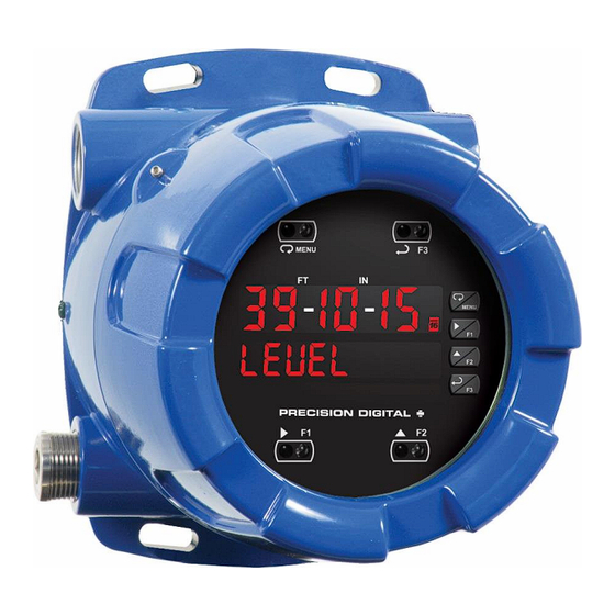
ProtEX-MAX PD8-6001 Explosion-Proof
Feet & Inches Meter Instruction Manual
• 0-20 mA, 4-20 mA, 0-5 V, 1-5 V, and ±10 V Inputs
• Feet & Inches Display Ideal for Level Applications
• Isolated 24 VDC @ 25 mA Transmitter Power Supply
• Multi-Pump Alternation Control
• Display a Single Input in Two Different Scales (e.g. Height & Volume)
• Signal Input Conditioning for Oddly Shaped and Round Horizontal Tanks
• 32-Point, Square Root, or Exponential Linearization
• Modern, Sleek and Practical Enclosure
• Display Mountable at 0°, 90°, 180°, & 270° Degrees
• Explosion-Proof, IP68, NEMA 4X Enclosure
• SafeTouch
®
Through-Glass Button Programming
• Flanges for Wall or Pipe Mounting
• Superluminous Sunlight Readable Display
• Free USB Programming Software & Cable
• 4 Relays + Isolated 4-20 mA Output Option
O
O
r
r
d
d
e
e
r
r
f
f
r
r
o
o
m
m
:
:
C
A
B
C
A
B
622 Mary Street; Suite 101; Warminster, PA 18974
Phone: 267-673-8117 - Fax: 267-673-8118
Sales@cabriggs.com
r
i
g
g
s
C
o
m
p
a
r
i
g
g
s
C
o
m
p
a
-
www.cabriggs.com
Process
n
y
n
y
www.predig.com
USB Install
Advertisement
Table of Contents
Troubleshooting

Subscribe to Our Youtube Channel
Related Manuals for PRECISION DIGITAL ProtEX-MAX PD8-6001 Series


Summary of Contents for PRECISION DIGITAL ProtEX-MAX PD8-6001 Series
- Page 1 ProtEX-MAX PD8-6001 Explosion-Proof Feet & Inches Meter Instruction Manual USB Install Process • 0-20 mA, 4-20 mA, 0-5 V, 1-5 V, and ±10 V Inputs • Feet & Inches Display Ideal for Level Applications • Isolated 24 VDC @ 25 mA Transmitter Power Supply •...
- Page 2 Disclaimer The information contained in this document is subject to change without notice. Precision Digital makes no representations or warranties with respect to the contents hereof and specifically disclaims any implied warranties of merchantability or fitness for a particular purpose.
-
Page 3: Table Of Contents
ProtEX-MAX PD8-6001 Explosion-Proof Feet & Inches Meter Instruction Manual Table of Contents --------------------------------------------------------- 29 Table of Contents -------------------------------------------3 Multi-Point Calibration & Scaling -------------------- 29 Table of Figures ---------------------------------------------4 Scaling the Meter (SCALE) ----------------------------- 30 Introduction --------------------------------------------------4 Dual-Scale for Level Application -------------------- 30 Ordering Information --------------------------------------5 Calibrating the Meter with External Source (Cal) 31 Specifications ------------------------------------------------5... -
Page 4: Table Of Figures
ProtEX-MAX PD8-6001 Explosion-Proof Feet & Inches Meter Instruction Manual F4 Operation --------------------------------------------------- 55 Factory Defaults & User Settings ----------------------- 57 Maximum/Minimum Readings ---------------------------- 55 Troubleshooting Tips---------------------------------------- 58 Troubleshooting ------------------------------------------ 56 Service ------------------------------------------------------- 59 Diagnostics Menu (diag) ----------------------------------- 56 Mounting Dimensions ----------------------------------- 59 Determining Software Version -------------------------- 56 EU Declaration of Conformity ------------------------ 61 Reset Meter to Factory Defaults ------------------------- 56... -
Page 5: Ordering Information
ProtEX-MAX PD8-6001 Explosion-Proof Feet & Inches Meter Instruction Manual Ordering Information SunBright Display Models 85-265 VAC Model 12-24 VDC Model Options Installed PD8-6001-6H0 PD8-6001-7H0 No options PD8-6001-6H7 PD8-6001-7H7 4 relays & 4-20 mA output *Model number for replacement option card. WARNING - Cancer and Reproductive Harm - www.P65Warnings.ca.gov Accessories... -
Page 6: Process Input
ProtEX-MAX PD8-6001 Explosion-Proof Feet & Inches Meter Instruction Manual Input Voltage ranges: greater than 500 k Max Power Maximum power dissipation limited to Current ranges: 50 - 100 Impedance (depending on Dissipation 15.1 W. resettable fuse impedance) Connections Screw terminals accept 12 to 22 AWG Input Current input protected by resettable wire... -
Page 7: Isolated 4-20 Ma Transmitter Output
ProtEX-MAX PD8-6001 Explosion-Proof Feet & Inches Meter Instruction Manual 300 – 19,200 bps Relay Reset User selectable via front panel buttons Baud Rate or digital inputs Transmit Programmable between 0 and 199 ms Automatic reset only (non-latching), Time Delay when the input passes the reset Data 8 bit (1 start bit, 1 or 2 stop bits) point. -
Page 8: Product Ratings And Approvals
ProtEX-MAX PD8-6001 Explosion-Proof Feet & Inches Meter Instruction Manual Product Ratings and Approvals; Enclosure: Type 4X; IP66 Class I, Division 1, Groups B, C, D Class II, Division 1, Groups E, F, G Class III, Division 1, T5/T6 Class I, Zone 1, AEx d, IIC Gb T5/T6 Zone 21, AEx tb IIIC T90°C;... -
Page 9: Compliance Information
ProtEX-MAX PD8-6001 Explosion-Proof Feet & Inches Meter Instruction Manual Compliance Information Safety UL & c-UL Listed USA & Canada UL 508 Industrial Control Equipment UL File Number E160849 Front Panel UL Type 4X, NEMA 4X, IP65; panel gasket provided Low Voltage EN 61010-1:2010 Directive Safety requirements for measurement, control, and laboratory use... -
Page 10: Safety Information
ProtEX-MAX PD8-6001 Explosion-Proof Feet & Inches Meter Instruction Manual Safety Information WARNINGS • Read complete instructions prior to installation and operation of the instrument. • Installation and service should be performed only by trained service personnel. Service requiring replacement of internal sub-components must be performed at the factory. •... -
Page 11: Pre-Installed Conduit/Stopping Plug
ProtEX-MAX PD8-6001 Explosion-Proof Feet & Inches Meter Instruction Manual Pre-Installed Conduit/Stopping Plug The PD8-6000 is supplied with two pre-installed conduit plugs for installations that do not require the use of all conduit entries. The conduit/stopping plugs include an internal 12mm hexagonal socket recess for removal. -
Page 12: Connections
ProtEX-MAX PD8-6001 Explosion-Proof Feet & Inches Meter Instruction Manual Connections • Static electricity can damage sensitive components. • Observe safe handling precautions for static-sensitive components. • Use proper grounding procedures/codes. • If the instrument is installed in a high voltage environment and a fault or installation error occurs, high voltage may be present on WARNINGS any lead or terminal. -
Page 13: Connectors Labeling
ProtEX-MAX PD8-6001 Explosion-Proof Feet & Inches Meter Instruction Manual Connectors Labeling The connectors’ label, affixed to the meter, shows the location of all connectors available with requested configuration. Do not disconnect the RJ45 M-LINK connector cable. Otherwise the instrument will not function properly. Warning! Figure 3. -
Page 14: Signal Connections
ProtEX-MAX PD8-6001 Explosion-Proof Feet & Inches Meter Instruction Manual Signal Connections Signal connections are made to a six-terminal connector labeled SIGNAL on Figure 3. The COM (common) terminal is the return for the 4-20 mA and the 10 V input signals. -
Page 15: Serial Communications Connections
ProtEX-MAX PD8-6001 Explosion-Proof Feet & Inches Meter Instruction Manual Serial Communications Connections The ProtEX-MAX has a 5 position terminal block for connecting RS-485 serial devices. Figure 8 details the wiring connections from the ProtEX-MAX to an RS-485 serial converter (such as the PDA7485 or PDA8485) for a four-wire network. -
Page 16: Figure 10: Rs-485 Wiring
ProtEX-MAX PD8-6001 Explosion-Proof Feet & Inches Meter Instruction Manual Figure 10: RS-485 Wiring Notes: 1. Termination resistors are optional and values depend on the cable length and characteristic impedance. Consult the cable manufacturer for recommendations. 2. Refer to RS-232 to RS-485 Converter documentation for further details. 3. -
Page 17: Using Pro Vu U Serial Adapters
ProtEX-MAX PD8-6001 Explosion-Proof Feet & Inches Meter Instruction Manual Figure 11: RS-485 Two-Wire Multi-Drop Wiring Notes: 1. Termination resistors are optional and values depend on the cable length and characteristic impedance. Consult the cable manufacturer for recommendations. 2. Refer to RS-232 to RS-485 Converter documentation for further details. 3. -
Page 18: Relay Connections
Figure 14. Low Voltage DC Loads Protection RC Networks Available from Precision Digital RC networks are available from Precision Digital and should be applied to each relay contact switching an inductive load. Part number: PDX6901. Note: Relays are de-rated to 1/14th HP (50 watts) with an inductive load. -
Page 19: F4 Digital Input Connections
ProtEX-MAX PD8-6001 Explosion-Proof Feet & Inches Meter Instruction Manual F4 Digital Input Connections A digital input, F4, is standard on the meter. This digital input is connected with a normally open contact across F4 and COM, or with an active low signal applied to F4. Figure 15. -
Page 20: Digital I/O Connections
ProtEX-MAX PD8-6001 Explosion-Proof Feet & Inches Meter Instruction Manual Digital I/O Connections The ProtEX-MAX has a 10 position terminal block for connecting digital inputs and outputs. DI 1-4 DO 1-4 5 VDC Figure 18: Digital I/O Connections The onboard digital inputs (1-4) are configured at the factory to function identically to the front panel pushbuttons (Menu, F1, F2, &... -
Page 21: Setup And Programming
ProtEX-MAX PD8-6001 Explosion-Proof Feet & Inches Meter Instruction Manual Setup and Programming The meter is factory calibrated prior to shipment to read in milliamps and volts depending on the input selection. The calibration equipment is traceable to NIST standards. Overview There are no jumpers to set for the meter input selection. -
Page 22: Front Panel Buttons And Status Led Indicators
ProtEX-MAX PD8-6001 Explosion-Proof Feet & Inches Meter Instruction Manual Front Panel Buttons and Status LED Indicators Symbol Description Status Feet and inches Fractions of an inch indicator designation separators (eighths or sixteenths) Menu Alarm 1-8 indicator Flashing: Relay in manual Right arrow/F1 control mode Flashing: Relay interlock... -
Page 23: Meterview Pro Software
ProtEX-MAX PD8-6001 Explosion-Proof Feet & Inches Meter Instruction Manual ® MeterView Pro Software The meter can also be programmed using the PC-based MeterView Pro software included with the meter. This software can be installed on any Microsoft® Windows® (XP/Vista/7/8/10) computer by connecting the meter’s onboard USB. -
Page 24: Display Functions & Messages
ProtEX-MAX PD8-6001 Explosion-Proof Feet & Inches Meter Instruction Manual Display Functions & Messages The meter displays various functions and messages during setup, programming, and operation. The following table shows the main menu functions and messages in the order they appear in the menu. Display Parameter Action/Setting... - Page 25 ProtEX-MAX PD8-6001 Explosion-Proof Feet & Inches Meter Instruction Manual Display Parameter Action/Setting Display Parameter Action/Setting Description Description FLS 2 Dis 2 Fail-safe 2 Set relays 2-4 fail-safe Display 2 Program display 2 value operation Out 2 Output 2 Program output 2 value DeLAY Delay Enter relay Time Delay...
-
Page 26: Main Menu
ProtEX-MAX PD8-6001 Explosion-Proof Feet & Inches Meter Instruction Manual Main Menu The main menu consists of the most level commonly used functions: Setup, Reset, Control, and Password. • Press Menu button to enter Programming Mode then press the Up arrow button to scroll main menu. •... -
Page 27: Setting Up The Meter (Setup)
ProtEX-MAX PD8-6001 Explosion-Proof Feet & Inches Meter Instruction Manual Setting Up the Meter (setup) The Setup menu is used to select: 1. Input signal the meter will accept 2. Dual-scale feature for some level applications 3. Select the display units/tags Note: Use the d-SCAL selection 4. -
Page 28: Setting The Input Units Or Custom Tags (Units)
ProtEX-MAX PD8-6001 Explosion-Proof Feet & Inches Meter Instruction Manual Setting the Input Units or Custom Tags (units) Enter the input unit or custom tag that will be displayed if d unit is selected as the display line 2 parameter. See the flow chart on page 32 to access the display menu to show the unit or tag on line 2. The engineering units or custom legends can be set using the following 7-segment character set: Display Character... -
Page 29: Programming The Meter (Prog)
ProtEX-MAX PD8-6001 Explosion-Proof Feet & Inches Meter Instruction Manual Programming the Meter (prog) It is very important to read the following information, before proceeding to program the meter: • The meter is factory calibrated prior to shipment to read in milliamps and volts depending on the input selection. -
Page 30: Scaling The Meter (Scale)
ProtEX-MAX PD8-6001 Explosion-Proof Feet & Inches Meter Instruction Manual Scaling the Meter (SCALE) The process input (4-20 mA, 10 VDC) can be scaled to display the process variable in engineering units. A signal source is not needed to scale the meter; simply program the inputs and corresponding display values. -
Page 31: Calibrating The Meter With External Source (Cal)
ProtEX-MAX PD8-6001 Explosion-Proof Feet & Inches Meter Instruction Manual Calibrating the Meter with External Source (Cal) Note: To scale the meter without a signal source refer to Scaling the Meter (SCALE), page 30. The meter can be calibrated to display the process variable in engineering units by applying the appropriate input signal and following the calibration procedure. -
Page 32: Setting The Display Parameter & Intensity (Dsplay)
ProtEX-MAX PD8-6001 Explosion-Proof Feet & Inches Meter Instruction Manual Setting the Display Parameter & Intensity (dsplay) Display line 1 can be programmed to display: 1. Process value 2. Relay set points 3. Max & min values 4. Modbus input Display line 2 can be programmed to display: 1. -
Page 33: Setting The Relay Operation (Relay)
ProtEX-MAX PD8-6001 Explosion-Proof Feet & Inches Meter Instruction Manual Setting the Relay Operation (relay) This menu is used to set up the operation of the relays. During setup, the relays do not follow the input and they will remain in the state found prior to entering the Relay menu. Caution! 1. -
Page 34: Setting Fail-Safe Operation
ProtEX-MAX PD8-6001 Explosion-Proof Feet & Inches Meter Instruction Manual Setting Fail-Safe Operation In fail-safe mode of operation, the relay coil is energized when the process variable is within safe limits and the relay coil is de-energized when the alarm condition exists. The fail-safe operation is set independently for each relay. Select on to enable or select off to disable fail-safe operation. -
Page 35: High Alarm With Fail-Safe Operation (Set > Reset)
ProtEX-MAX PD8-6001 Explosion-Proof Feet & Inches Meter Instruction Manual High Alarm with Fail-Safe Low Alarm with Fail-Safe Operation Operation (Set > Reset) (Set < Reset) Note: Relay coil is energized in non-alarm Note: Relay coil is energized in non-alarm condition. In case of power failure, relay will condition. -
Page 36: Pump Alternation Control Operation
ProtEX-MAX PD8-6001 Explosion-Proof Feet & Inches Meter Instruction Manual Pump Alternation Control Operation Relay Sampling Operation Input Reset Sample Sample Sample Time Time Time Relay When the signal crosses the set point, the relay trips and the sample time starts. After the sample time has elapsed, the relay resets. -
Page 37: Signal Loss Or Loop Break Relay Operation
ProtEX-MAX PD8-6001 Explosion-Proof Feet & Inches Meter Instruction Manual Signal Loss or Loop Break Relay Operation The following graph shows the loop break relay operation for a high alarm relay. Input Reset de-energized energized Relay Loop Break = Ignore Relay Loop Break = Off Relay Loop Break = On... -
Page 38: Relay Operation Details
ProtEX-MAX PD8-6001 Explosion-Proof Feet & Inches Meter Instruction Manual Relay Operation Details Overview The relay capabilities of the meter expand its usefulness beyond simple indication to provide users with alarm and control functions. These capabilities include front panel alarm status LEDs as well as either 2 or 4 optional internal relays. -
Page 39: Latching And Non-Latching Relay Operation
ProtEX-MAX PD8-6001 Explosion-Proof Feet & Inches Meter Instruction Manual Latching and Non-Latching Relay Operation The relays can be set up for latching (manual reset) or Relay terminology for following tables non-latching (automatic reset) operation. Terminology Relay Condition The On and Off terminology does not refer to the status of Alarm (Tripped) the relay’s coil, which depends on the fail-safe mode Normal (Reset) -
Page 40: Acknowledging Relays
ProtEX-MAX PD8-6001 Explosion-Proof Feet & Inches Meter Instruction Manual Acknowledging Relays There are two ways to acknowledge relays programmed for manual reset: 1. Via the programmable front panel function keys F1-F3 (Default: F3 assigned to ACK). 2. Remotely via a normally open pushbutton wired across one of the digital inputs and the +5 V terminals on the digital I/O modules, or using the F4 digital input, which is triggered with a contact closure to COM, or with an active low signal (see page 19). - Page 41 ProtEX-MAX PD8-6001 Explosion-Proof Feet & Inches Meter Instruction Manual Application #2: Pump Alternation Using Relays 3 & 4 1. Relays 1 and 2 are set up for low and high alarm indication. 2. Relays 3 and 4 are set up for pump alternation. Set and Reset Point Programming Relay Set Point...
-
Page 42: Setting Up The Interlock Relay (Force On) Feature
ProtEX-MAX PD8-6001 Explosion-Proof Feet & Inches Meter Instruction Manual Setting Up the Interlock Relay (Force On) Feature Relays 1-4 can be set up as interlock relays. To set up the relays for the interlock feature: 1. Access the Setup – Relay – Action menu and set the action to off. 2. -
Page 43: Reset Menu (Reset)
ProtEX-MAX PD8-6001 Explosion-Proof Feet & Inches Meter Instruction Manual Reset Menu (reset) The Reset menu is used to reset the maximum or minimum reading (peak or valley) reached by the process; both may be reset at the same time by selecting “reset high & low” (rst HL). Control Menu (Contrl) The Control menu is used to control the 4-20 mA analog output and the relays manually, ignoring the input. -
Page 44: Making Changes To A Password Protected Meter
ProtEX-MAX PD8-6001 Explosion-Proof Feet & Inches Meter Instruction Manual Making Changes to a Password Protected Meter If the meter is password protected, the meter will display the message Locd (Locked) when the Menu button is pressed. Press the Enter button while the message is being displayed and enter the correct password to gain access to the menu. -
Page 45: Advanced Features Menu
ProtEX-MAX PD8-6001 Explosion-Proof Feet & Inches Meter Instruction Manual Advanced Features Menu To simplify the setup process, functions not needed for most applications are located in the Advanced Features menu. Press and hold the Menu button for three seconds to access the advanced features of the meter. Advanced Features Menu &... - Page 46 ProtEX-MAX PD8-6001 Explosion-Proof Feet & Inches Meter Instruction Manual Display Parameter Action/Setting Display Parameter Action/Setting Calib Ln2 Hi Calibrate Calibrate 4-20 mA output Line 2 High Max on line 2 (internal reference source Ln2 lo Line 2 Low Min on line 2 used for scaling the output) Ln2 Hl Line 2...
-
Page 47: Noise Filter (Filter)
RS-232, or RS-485 option is required; see Ordering Information on page 5 for details. Do not connect any equipment other than Precision Digital’s expansion modules, cables, or meters to the RJ45 M-LINK connector. Otherwise damage will occur to Warning! the equipment and the meter. -
Page 48: Serial Communications Overview
ProtEX-MAX PD8-6001 Explosion-Proof Feet & Inches Meter Instruction Manual Serial Communications Overview RS-232 and RS-485 are standard interfaces approved by the Electronic Industries Alliance (EIA) for connecting serial devices. In EIA terms, the device (e.g. meter) that connects to the interface is called a Data Communications Equipment (DCE) and the device to which it connects (e.g. -
Page 49: Select Menu (Select)
ProtEX-MAX PD8-6001 Explosion-Proof Feet & Inches Meter Instruction Manual Select Menu (SElect) The Select menu is used to select the signal input conditioner applied to the input (linear or round horizontal tank), low-flow cutoff, and analog output programming. The multi- point linearization is part of the linear function selection. - Page 50 ProtEX-MAX PD8-6001 Explosion-Proof Feet & Inches Meter Instruction Manual Round Horizontal Tank Linearization (rHt) This function automatically calculates the volume in a round horizontal tank with flat ends. This option is only available on PV2 since PV1 is the designated level indicator. Set the display for the desired decimal point and engineering units before entering the round horizontal tank function.
-
Page 51: Low-Flow Cutoff (Cutoff)
ProtEX-MAX PD8-6001 Explosion-Proof Feet & Inches Meter Instruction Manual Low-Flow Cutoff (CutofF) The low-flow cutoff feature allows the meter to be programmed so that the often-unsteady outputs from level transmitters, or levels that read close to zero but do not reach zero due to setup constraints, may display zero on the meter. - Page 52 ProtEX-MAX PD8-6001 Explosion-Proof Feet & Inches Meter Instruction Manual Function Keys & Digital I/O Available Settings Refer to the following table for descriptions of each available function key or digital I/O setting. Display Description Display Description Ln2 Hi Rst Hi Display maximum display value on Reset the stored maximum display line 2...
-
Page 53: Internal Source Calibration (Ical)
ProtEX-MAX PD8-6001 Explosion-Proof Feet & Inches Meter Instruction Manual Internal Source Calibration (ICAL) The meter is factory calibrated prior to shipment to read in milliamps and volts depending on the input selection. The calibration equipment is traceable to NIST standards. The use of calibrated signal sources is necessary to calibrate the internal source of the meter. -
Page 54: Meter Operation
ProtEX-MAX PD8-6001 Explosion-Proof Feet & Inches Meter Instruction Manual Meter Operation The meter is capable of accepting current (0-20 mA, 4-20 mA) and voltage signals (0-5 V, 1-5 V, 0-10 V, 10 V) and displaying these signals in engineering units from -9 ) - 99 ) on display line 1 and units from -99999 to 999999 on display line 2 (e.g. -
Page 55: F4 Operation
ProtEX-MAX PD8-6001 Explosion-Proof Feet & Inches Meter Instruction Manual F4 Operation A digital input, F4, is standard on the meter. This digital input is programmed identically to function keys F1, F2, and F3. The input is triggered with a contact closure to COM, or with an active low signal. During operation, F4 operates according to the way it has been programmed in the Advanced Features –... -
Page 56: Troubleshooting
ProtEX-MAX PD8-6001 Explosion-Proof Feet & Inches Meter Instruction Manual Troubleshooting Due to the many features and functions of the meter, it’s possible that the setup of the meter does not agree with what an operator expects to see. If the meter is not working as expected, refer to the Diagnostics menu and consult the recommendations described below. -
Page 57: Factory Defaults & User Settings
ProtEX-MAX PD8-6001 Explosion-Proof Feet & Inches Meter Instruction Manual Factory Defaults & User Settings The following table shows the factory setting for most of the programmable parameters on the meter. Parameter Display Default Setting Parameter Display Default Setting Input Off 3 Input type 4-20 mA Off delay relay 3... -
Page 58: Troubleshooting Tips
ProtEX-MAX PD8-6001 Explosion-Proof Feet & Inches Meter Instruction Manual Troubleshooting Tips Symptom Check/Action If mechanical button was pushed. The SafeTouch buttons will be re- SafeTouch buttons do not respond enabled automatically 60 seconds after the last button push. If slide switch on connector board is in DISABLE position, switch to ENABLE. -
Page 59: Service
ProtEX-MAX PD8-6001 Explosion-Proof Feet & Inches Meter Instruction Manual Service WARNINGS • Installation and service should be performed only by trained service personnel. Service requiring replacement of internal sub-components must be performed at the factory. • Disconnect from supply before opening enclosure. Keep cover tight while circuits are alive. - Page 60 ProtEX-MAX PD8-6001 Explosion-Proof Feet & Inches Meter Instruction Manual This Page Intentionally Left Blank...
-
Page 61: Eu Declaration Of Conformity
SIRA 10 ATEX M462 ATEX Notified Body for Quality Assurance: Sira Certification Service, NB 0518 Unit 6, Hawarden Industrial Park Hawarden, Deeside, CH5 3US, UK Signed for and on behalf of Precision Digital Corporation: Name: Jeffrey Peters Company: Precision Digital Corporation... - Page 62 ProtEX-MAX PD8-6001 Explosion-Proof Feet & Inches Meter Instruction Manual How to Contact Precision Digital • For Technical Support please Call: (800) 610-5239 or (508) 655-7300 Fax: (508) 655-8990 Email: support@predig.com • For Sales Support or to place an order please...
Need help?
Do you have a question about the ProtEX-MAX PD8-6001 Series and is the answer not in the manual?
Questions and answers