Table of Contents
Advertisement
Quick Links
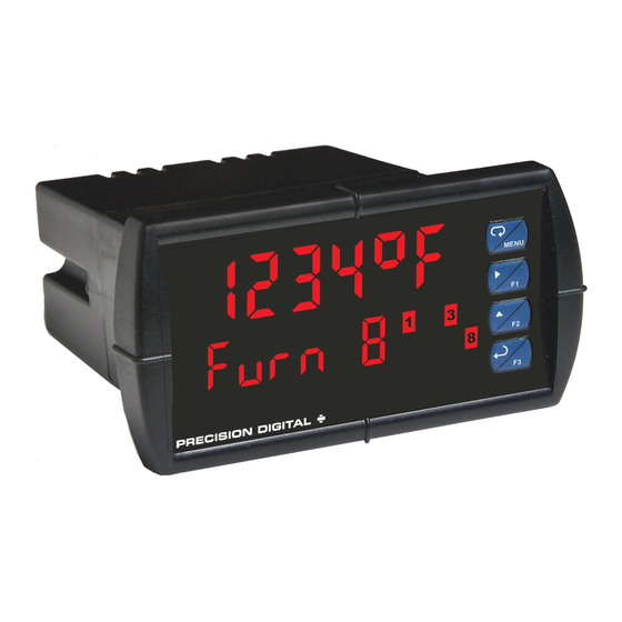
™ PD7000 Temperature Meter
P
V
RO
U
Instruction Manual
•
1/8 DIN Digital Panel Temperature Meter with NEMA 4X, IP65 Front
•
J, K, T, E, R, S, B, N, C Thermocouples
•
100 or 1000 Ω Platinum, 10 Ω Copper, 120 Ω Nickel RTDs
•
Optional Isolated 4-20 mA Output Turns the Meter into a Temperature Transmitter
•
1° or 0.1° Resolution
•
Averages up to 10 RTD Sensors
•
Automatic Cold Junction Compensation
•
Dual-Line 6-Digit Display, 0.6" (15 mm) & 0.46" (12 mm)
•
2 or 4 Relays with Interlocking Capability + Isolated 4-20 mA Output Options
•
Free PC-Based, Onboard, MeterView Pro USB Programming Software
•
No Assembly Required
•
Optional SunBright Display Models for Outdoor Applications
•
Operating Temperature Range: -20 to 65°C (-4 to 149°F)
•
UL & C-UL Listed. E160849; 508 Industrial Control Equipment
•
Input Power Options: 85-265 VAC / 90-265 VDC or 12-24 VDC / 12-24 VAC
•
Programmable Display, Function Keys & Digital Input
•
External 4-Relay & Digital I/O Expansion Modules
•
RS-232 & RS-485 Serial Communication Options with Modbus RTU
•
Password Protection
•
Wide Assortment of NEMA 4X Enclosures for up to Ten Meters
•
Light / Horn & Reset Button Accessory
•
Control Station Accessory for Remote Operation of P
•
3-Year Warranty
PRECISION DIGITAL CORPORATION
233 South Street • Hopkinton MA 01748 USA
Tel (800) 343-1001 • Fax (508) 655-8990
www.predig.com
MeterView Pro
USB Install
V
RO
U
Advertisement
Table of Contents
Troubleshooting

Related Manuals for PRECISION DIGITAL PROVU PD7000 Series


Summary of Contents for PRECISION DIGITAL PROVU PD7000 Series
- Page 1 Wide Assortment of NEMA 4X Enclosures for up to Ten Meters • Light / Horn & Reset Button Accessory • Control Station Accessory for Remote Operation of P • 3-Year Warranty PRECISION DIGITAL CORPORATION 233 South Street • Hopkinton MA 01748 USA Tel (800) 343-1001 • Fax (508) 655-8990 www.predig.com...
- Page 2 When using the Micro USB connection, DO NOT apply AC or DC power to the meter. Anyone using this product for such applications does so at his/her own risk. Precision Digital The easiest and quickest way to program your P Corporation shall not be held liable for damages meter is to use the FREE MeterView Pro resulting from such improper use.
-
Page 3: Table Of Contents
™ PD7000 Temperature Meter Instruction Manual Table of Contents Introduction ......................6 Ordering Information ................... 6 Specifications....................... 7 General ......................7 Temperature Input ................... 8 Relays ....................... 8 Isolated 4-20 mA Output ................. 9 USB Connection ....................9 On-Board Digital Input (F4) ................9 Modbus RTU Serial Communications ............ - Page 4 ™ PD7000 Temperature Meter Instruction Manual Time Delay Operation ................. 25 Relay Operation Details ................25 Overview ..................... 25 Relays Auto Initialization ................25 Fail-Safe Operation ..................25 Front Panel LEDs ..................26 Latching and Non-Latching Relay Operation ..........26 Non-Latching Relay (Auto) .................
- Page 5 ™ PD7000 Temperature Meter Instruction Manual Table of Figures Figure 1: 1/8 DIN Panel Cutout and Mounting ..........11 Figure 2. Meter Dimensions - Side View ............11 Figure 3. Meter Dimensions - Top View ............11 Figure 4. PD7000-##0 Connectors Label ............13 Figure 5.
-
Page 6: Introduction
™ PD7000 Temperature Meter Instruction Manual Ordering Information Introduction Standard Models The P PD7000 temperature meter accepts a direct temperature input from a wide range of 85-265 VAC 12-24 VDC Options Installed temperature measurement devices (type J, K, T, E, R, Model Model S, B, N, and C thermocouples and 100 or 1000 Ω... -
Page 7: Specifications
™ PD7000 Temperature Meter Instruction Manual Specifications Environmental Operating temperature range: -20 to 65°C (-4 to 149°F) Storage temperature range: Except where noted all specifications apply to -40 to 85°C (-40 to 185°F) operation at +25°C. Relative humidity: General 0 to 90% non-condensing Connections Removable screw terminal blocks accept Line 1: 0.60"... -
Page 8: Temperature Input
™ PD7000 Temperature Meter Instruction Manual Temperature Input Relays Inputs Thermocouple: J, K, T, E, R, S, B, N, C Rating 2 or 4 SPDT (Form C) internal and/or RTD: 100 Ω platinum (0.00385 & 0.00392 4 SPST (Form A) external; rated 3 A coefficients), 10 Ω... -
Page 9: Isolated 4-20 Ma Output
™ PD7000 Temperature Meter Instruction Manual ® Isolated 4-20 mA Output Modbus RTU Serial Communications Output PV (temperature), max, min, set points 1-8, Source Modbus PV input, or manual control mode 1 – 247 (Meter address) Slave Id Scaling 1.000 to 23.000 mA for any display range 300 –... -
Page 10: Compliance Information
™ PD7000 Temperature Meter Instruction Manual Compliance Information Safety Information Safety • Read complete instructions prior to installation UL & c-UL Listed USA & Canada and operation of the meter. UL 508 Industrial Control Equipment UL File Number E160849 Front Panel UL Type 4X, NEMA 4X, IP65;... -
Page 11: Panel Mounting Instructions
™ PD7000 Temperature Meter Instruction Manual Mounting Dimensions Panel Mounting Instructions • Prepare a standard 1/8 DIN panel cutout – 3.622" x 1.772" (92 mm x 45 mm). Refer to Figure 1: 1/8 DIN Panel Cutout and Mounting below for more details. •... -
Page 12: Installation Overview
™ PD7000 Temperature Meter Instruction Manual Once the driver is installed, an AutoPlay Installation Overview dialog should appear for the drive We recommend the following sequence for getting the “MAINSTAL.” Click “Open folder to view meter into service: files.” DO NOT apply AC or DC power to the meter. Connect the meter to the PC with the USB cable provided. -
Page 13: Connections
RELAY2 RELAY1 • DO NOT connect any equipment other than Precision Digital’s expansion modules, cables, or meters to the RJ45 M LINK connector. Otherwise damage will occur to the equipment and the 1 2 3 4 5 6 7 8 TC 100 meter. -
Page 14: Signal Connections
™ PD7000 Temperature Meter Instruction Manual Signal Connections SIGNAL Signal connections are made to a three-terminal connector labeled SIGNAL. Thermocouple and RTD Connections TYPE RANGE M-LINK The following figures show examples for thermocouple and RTD connections. The TYPE selector switch must be set to the proper Sensor position for the meter to accept the selected RTD or TC input. -
Page 15: Relay Connections
Relay connections are made to two six-terminal connectors labeled RELAY1 – RELAY4. Each relay’s RC networks are available from Precision Digital and C terminal is common only to the normally open (NO) should be applied to each relay contact switching an and normally closed (NC) contacts of the inductive load. -
Page 16: External Relays & Digital I/O Connections
™ PD7000 Temperature Meter Instruction Manual External Relays & Digital I/O Interlock Relay Feature Connections As the name implies, the interlock relay feature reassigns one, or more, alarm/control relays for use The relay and the digital I/O expansion modules as interlock relay(s). Interlock contact(s) are wired to PDA1004 &... -
Page 17: Setup And Programming
™ PD7000 Temperature Meter Instruction Manual Setup and Programming Front Panel Buttons and Status LED Indicators There is no need to recalibrate the meter when first received from the factory. Simply select the input type, ºF or ºC, and decimal point. -
Page 18: Display Functions & Messages
™ PD7000 Temperature Meter Instruction Manual Display Functions & Messages Display Functions & Messages The meter displays various functions and messages Display Parameter Action/Setting during setup, programming, and operation. The Description following table shows the main menu functions and Disable relay and front messages in the order they appear in the menu. -
Page 19: Main Menu
™ PD7000 Temperature Meter Instruction Manual Main Menu Display Functions & Messages The main menu consists of the most commonly used Display Parameter Action/Setting functions: Setup, Reset, Control, and Password. Description • Press Menu button to enter Programming Mode Rst HL Reset Press Enter to reset max &... -
Page 20: Setting Numeric Values
™ PD7000 Temperature Meter Instruction Manual Setting the Input Signal (Input) Setting Numeric Values Enter the Input menu to set up the meter to accept The numeric values are set using the Right and Up thermocouple (tc) or RTD (rtd) inputs. The Type arrow buttons. -
Page 21: Setting The Display Parameter & Intensity (Dsplay)
™ PD7000 Temperature Meter Instruction Manual Setting the Display Parameter & Display Intensity (d-Inty) Intensity (dsplay) The meter has eight display intensity levels to give the best performance under various lighting conditions. Display line 1 (line 1) can be programmed to Select intensity 8 for outdoor applications. -
Page 22: Setting The Relay Operation (Relay)
™ PD7000 Temperature Meter Instruction Manual Setting the Relay Action Setting the Relay Operation Operation of the relays is programmed in the Action (relay) menu. The relays may be set up for any of the This menu is used to set up the operation of the following modes of operation: relays. -
Page 23: Programming Set And Reset Points
™ PD7000 Temperature Meter Instruction Manual Programming Set and Reset Relay and Alarm Operation Points Diagrams High alarm indication: program set point above reset The following graphs illustrate the operation of the point. relays, status LEDs, and ACK button. Low alarm indication: program set point below reset High Alarm Operation (Set >... -
Page 24: High Alarm With Fail-Safe Operation (Set > Reset)
™ PD7000 Temperature Meter Instruction Manual High Alarm with Fail-Safe Relay Sampling Operation Operation (Set > Reset) When the signal crosses the set point, the relay trips and the sample time starts. After the sample time has elapsed, the relay resets. The cycle repeats every time the set point is crossed, going up for high alarms and going down for low alarms. -
Page 25: Time Delay Operation
™ PD7000 Temperature Meter Instruction Manual Time Delay Operation Relay Operation Details The following graphs show the operation of the time Overview delay function. The relay capabilities of the meter expand its usefulness beyond simple indication to provide users with alarm and control functions. These capabilities include front panel alarm status LEDs as well as either 2 or 4 optional internal relays and/or 4 external relays expansion module. -
Page 26: Front Panel Leds
™ PD7000 Temperature Meter Instruction Manual Front Panel LEDs Non-Latching Relay (Auto) The LEDs on the front panel provide status indication In this application, the meter is set up for automatic for the following: reset (non-latching relay). Acknowledging the alarm while it is still present has no effect on either the LED Status Status... -
Page 27: Latching Relay With Clear (Lt-Clr)
™ PD7000 Temperature Meter Instruction Manual Latching Relay with Clear (Lt-Clr) Setting Up the Interlock Relay (Force On) Feature In this application, the meter is set up for manual reset only after the signal passes the reset point Relays 1-4 can be set up as interlock relays. To set (alarm condition has cleared). -
Page 28: Scaling The 4-20 Ma Analog Output (Aout)
™ PD7000 Temperature Meter Instruction Manual Scaling the 4-20 mA Analog Reset Menu (reset) Output (Aout) The Reset menu is used to reset the maximum or minimum reading (peak or valley) reached by the The 4-20 mA analog output can be scaled to provide process;... -
Page 29: Setting Up The Password (Pass)
™ PD7000 Temperature Meter Instruction Manual Disabling Password Protection Setting Up the Password (pass) To disable the password protection, access the The Password menu is used for programming three Password menu and enter the correct password levels of security to prevent unauthorized changes to twice, as shown below. -
Page 30: Advanced Features Menu
™ PD7000 Temperature Meter Instruction Manual Advanced Features Menu Display Parameter Action/Setting To simplify the setup process, functions not needed Parity Parity Select parity for most applications are located in the Advanced Even, Odd, or None with 1 or 2 stop bits Features menu. -
Page 31: Offset Adjust (Adjust)
™ PD7000 Temperature Meter Instruction Manual Recommended Calibration Points Display Parameter Action/Setting To recalibrate the meter, it is recommended to use nmref Measured Enter the measured the Fahrenheit scale; this will give a greater degree of temp reference temperature accuracy to the calibration. The scale can be changed reference in degrees Celsius to the Celsius scale after calibration is completed. -
Page 32: Noise Filter Bypass (Bypass)
• DO NOT connect any equipment other than Break: Analog output value when input break is Precision Digital’s expansion modules, cables, or detected meters to the RJ45 M LINK connector. Otherwise Max: Maximum analog output value allowed damage will occur to the equipment and the regardless of input meter. -
Page 33: Programmable Function Keys User Menu (User)
™ PD7000 Temperature Meter Instruction Manual Analog Output Calibration Function Keys & Digital I/O Available Settings To perform the analog output calibration, it is recommended to use a milliamp meter with a Refer to the following table for descriptions of each resolution of at least 0.1 µA to measure the output available function key or digital I/O setting. -
Page 34: Internal Temperature Calibration (Ical)
™ PD7000 Temperature Meter Instruction Manual Internal Temperature Calibration 10. This completes the calibration of all the thermocouple ranges. (ICAL) The meter is factory calibrated prior to shipment to read temperature in degrees Fahrenheit with calibration equipment that is certified to NIST standards. -
Page 35: Meter Operation
™ PD7000 Temperature Meter Instruction Manual Meter Operation Maximum/Minimum Readings The max & min readings (peak & valley) reached by The meter is capable of accepting a variety of the process can be displayed either continuously or thermocouples and RTDs. momentary: The dual-line display can be customized by the user to Display briefly by assigning to the F1-F3... -
Page 36: Troubleshooting
™ PD7000 Temperature Meter Instruction Manual Troubleshooting Reset Meter to Factory Defaults When the parameters have been changed in a way The rugged design and the user-friendly interface of that is difficult to determine what’s happening, it might the meter should make it unusual for the installer or be better to start the setup process from the factory operator to refer to this section of the manual. -
Page 37: Factory Defaults & User Settings
™ PD7000 Temperature Meter Instruction Manual Factory Defaults & User Settings Parameter Display Default Setting The following table shows the factory setting for most Off delay relay 4 Off 4 0.0 sec of the programmable parameters on the meter. ignore Input break relay 1 Ignore ignore... -
Page 38: Troubleshooting Tips
™ PD7000 Temperature Meter Instruction Manual Troubleshooting Tips This meter is a highly sophisticated instrument with an extensive list of features and capabilities. If the front panel buttons are used to program the meter, it may be a difficult task to keep everything straight. That is why we strongly recommend the use of the free MeterView Pro software for all programming activities. -
Page 39: Eu Declaration Of Conformity
EN 55022:2010, EN 61000-6-2:2005, EN 61010-1:2010, and EN 61326:2013 and there were no major technical changes affecting the latest technical knowledge for the products listed above. Product Markings: Signed for and on behalf of Precision Digital Corporation: Name: Jeffrey Peters Company:... - Page 40 ™ PD7000 Temperature Meter Instruction Manual Contact Precision Digital Technical Support Call: (800) 610-5239 or (508) 655-7300 Fax: (508) 655-8990 Email: support@predig.com Sales Support Call: (800) 343-1001 or (508) 655-7300 Fax: (508) 655-8990 Email: sales@predig.com Place Orders Email: orders@predig.com For the latest version of this manual please visit www.predig.com...
Need help?
Do you have a question about the PROVU PD7000 Series and is the answer not in the manual?
Questions and answers